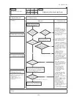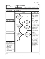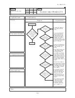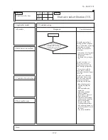
-
359
-
'12 • PAC-T-173
RD
Orange
OR
Y
ellow
/
Green
Y
/
G
Black
BK
Y
ellow
Y
White
WH
Red
Indoor
unit
Power source
1 Phase
220-240V
50Hz
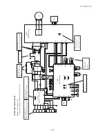
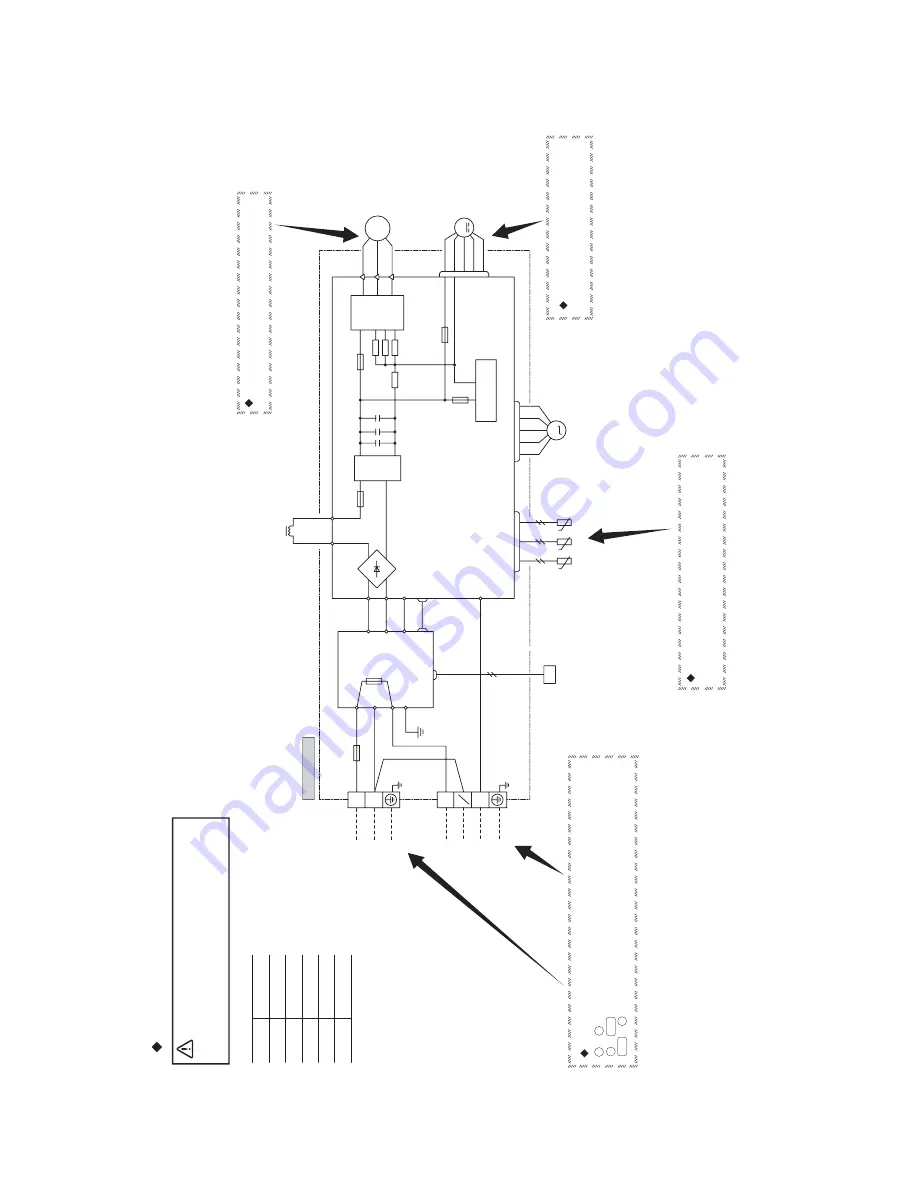
Inspection of resistance value of sensor
Remove the connector and check the resistance value.
See the section of sensor characteristics on page 400, 401.
Inspection power transistor
Remove the fasten terminal and test output voltage
Check point of outdoor unit
Inspection of outdoor fan motor
See page 410.
Power source and serial signal inspection
1
to
2/N
:A
C
220/230/240V
2/N to 3 : Normal if the voltage oscillates between DC 0 and approx. 20V
CAUTION- HIGH VOLTAGE
High
voltage
is
produced
in
the
control
box.
Don't
touch
electrical
parts
in
the
control
box
for
5
minutes
after
the
unit
is
stopped.
Color symbol
L
to
N
:
AC 220/230/240V
Models SRC40ZJX-S, 50ZJX-S, 60ZJX-S
Outdoor unit
M
T2
T1
S
BK
WH
RD
V
W
U
PCB
ASSY
(
MAIN
)
M
M
R
TRANSIST
OR
POWER
CIRCUIT
SWITCHING POWER
250V 2A
F1
250V
20A
F2
F3 250V
1A
W
V
U
P
NU
NV
NW
CNTH
CNEEV
CNF
A
N
tº
3
〜
ACTIVE
FIL
TER
UNIT
250V
20A
F8
OR
Y
S-2
tº
tº
BK
WH
WH
BK
PCB
ASSY
(
SUB
)
S-1
CNSUB
CNMAIN
250V 10A
F10
S
R
IN
R
OUT
BK
WH
G1
Y
/
G
BR
IN
S
O
R
O
N
L
250V
20A
FUSE
2
1
N
3
Y
/
G
Y
/
G
CN20S
C-2
RD
20S
RD
T1
T2
TH1
T
H2
TH3
EEV
FMo
CM
WH
L
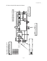
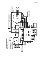
(8) Outdoor unit controller failure diagnosis circuit diagram
Summary of Contents for FDC Series
Page 95: ... 94 12 PAC T 173 Models FDT100VF 125VF 140VF H H H H H C B A F G D G PJF000Z285 ...
Page 98: ... 97 12 PAC T 173 Models FDEN60VF 71VF C 2 C 1 A B A B D C 1 C 2 C 1 C 2 E G F B PFA003Z817 ...
Page 113: ... 112 12 PAC T 173 b Wireless remote controller RCN E1R 60 17 150 Unit mm ...
Page 278: ... 277 12 PAC T 173 ー K ...
Page 346: ... 345 12 PAC T 173 Power PCB 1BSU OVNCFS 4GRNCEG VJG 2 ...
Page 518: ... 517 12 PAC T 173 3 5 SUPER LINK E BOARD SC ADNA E F SL2NA E and SL3N AE BE to control ...
Page 519: ... 518 12 PAC T 173 ...


