background image

-

 490 

-

 '12 • PAC-T-173

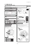
3.1 WIRELESS KIT

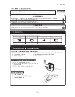
Pressing  ACL  and  AIR FLOW  button at the same time or 

inserting the batteries with pressing  AIR FLOW  button will 

customize the signal.

Instruct the customer how to operate it correctly referring to the instruction manual.

Accessories

Please make sure that you have all of the following accessories.

Receiver

Wireless
remote
controller

Parts set

Remote controller
holder

Wood screw for holder

AAA dry cell battery
(RO3)

<To change the settings>

 Remove the cover by unscrewing two screws from the back of receiver.

 Change the setting by the switch on PCB.

Screws

 Receiver

Backside

Backside

Default settings

Cover

Switch

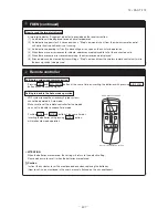
  When SW1 is turned to OFF position, change the corresponding remote controller setting as

 follows:

How to change the remote controller setting

Note

 When the batteries are removed, the setting will return


to the default setting.


Please make sure to reset it when the batteries are

 replaced.

Caution

Instruct the customer to set the mentioned above when 
replacing the batteries.
(How to set is also mentioned in the user’s manual 
attached on the air conditioner.)

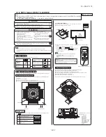
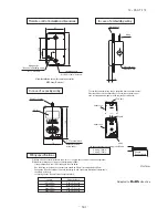
Installation of the receiver

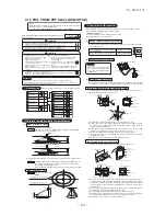
  Loosen the bolts which fix the panel and make a gap between the panel and the indoor unit

  Put the wiring of the receiver through the opening.

Put the wiring on the notch on the control box so as not to be pinched by the control box and lid as 

 shown 

below.

  Connect the wiring to the terminal block provided in the control box. (Non- polarized)

  Attach the receiver to the panel according to the panel installation manual.

  Fix the wiring with the clamp so that the wiring do not contact the edge of control box’s metal sheet.

  Reattach the control box lid with 3 screws removed.

Note: Make sure the wires not to be pinched by any other parts like panel, control box and indoor unit.

Terminal block in the indoor
unit control box

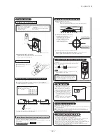
How to install the receiver

The receiver can be installed by replacing with a corner panel on the applicable decorative panel.

Preparation before installation

  Attach the decorative panel onto the air conditioner according to the installation manual for 

the panel.

  Remove the air return grille.

  Remove a corner panel located on the refrigerant pipes side.

 Remove three screws and detach the cover (indicated as shadowed area) from the control 

box of the air conditioner.

Setting on site

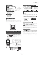
  PCB on the receiver has the following switches to set the functions. Default setting is shown


with          mark.

Customized signal setting to avoid
mixed communication

Receiver master/slave setting

Buzzer valid/Invalid

Auto restart

Normal
Remote

Master
Slave

Valid
Invalid

Valid
Invalid

Refrigerant pipes

Drain pipe

  Fasten the wiring to the terminal securely and hold the cable securely so as not to apply 


unexpected stress on the terminal.


Loose connection or hold will cause abnormal heat generation or fire.

Make sure the power supply is turned off when electric wiring work. 


Otherwise, electric shock, malfunction and improper running may occur.

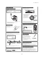
  DO NOT install the wireless kit at the following places in order to avoid malfunction.

  DO NOT leave the wireless kit without the cover.


In case the cover needs to be detached, protect the receiver with a packaging box or bag 

     in order to keep it away from water and dust.

(1) Places exposed to direct sunlight
(2) Places near heat devices
(3) High humidity places
(4) Hot surface or cold surface enough to 

generate condensation

(5) Places exposed to oil mist or steam directly
(6) Uneven surface
(7) Places affected by the direct airflow of the 

AC unit.

(8) Places where the receiver is influenced by 

the fluorescent lamp (especially inverter 
type) or sunlight.

(9) Places where the receiver is affected by 

infrared rays of any other communication 
devices

(10)Places where some object may obstruct the 

communication with the remote controller

Radio interference prevention mode

WARNING

CAUTION

For the installation method of the air conditioner itself, refer to the installation manual enclosed in the 
package.

Attention

3.1.1 FDT Series (RCN-T-36W-E)

PJF012D010

Notes :
Following functions of FDT Type-F indoor unit series are not able to be set with this wireless remote control (RCN-TC-36W-E).
    1. Individual flap control system
    2. 4-fan speed setting (P-Hi/Hi/Me/Lo) 

ĺ

3-fan speed setting (Hi/Me/Lo)

Summary of Contents for FDC Series

Page 1: ...ingle type FDUM50ZJXVF 60ZJXVF 71VNXVF 100VNXVF 100VSXVF 125VNXVF 125VSXVF 140VNXVF 140VSXVF DUCT CONNECTED HIGH STATIC PRESSURE TYPE Single type FDU71VNXVD 100VNXVD 100VSXVD 125VNXVD 125VSXVD 140VNXVD 140VSXVD FLOOR STANDING TYPE Single type FDF71VNXVD 100VNXVD 100VSXVD 125VNXVD 125VSXVD 140VNXVD 140VSXVD Twin type FDUM100VNXPVF 100VSXPVF 125VNXPVF 125VSXPVF 140VNXPVF 140VSXPVF Triple type FDUM14...

Page 2: ... 1 12 PAC T 173 TABLE OF CONTENTS 1 HYPER INVERTER PACKAGED AIR CONDITIONERS 2 2 V MULTI SYSTEM 468 3 OPTION PARTS 489 ...

Page 3: ...eiling cassette 4way compact type FDTC 25 5 Duct connected Low Middle static pressure type FDUM 61 1 Ceiling cassette 4way type FDT 154 3 Ceiling suspended type FDEN 169 6 Floor standing type FDF 190 7 Wall mounted type SRK 195 4 Duct connected High static pressure type FDU 179 2 Ceiling cassette 4way compact type FDTC 164 5 Duct connected Low Middle static pressure type FDUM 181 1 9 3 Correction ...

Page 4: ...g cooling heating 297 4 Timer operation 298 5 Remote controller display during the operation stop 299 6 Hot staet Cold draft prevention at heating 299 7 Hot keep 299 301 8 Thermostat operation 300 9 Filter sign 301 301 12 Drain motor DM control 10 Compressor inching prevention control 11 Drain pump control 301 303 302 15 Heating overload protection 13 Operation check drain pump test run operation ...

Page 5: ...8 26 High power operation RC EX1 only 24 Room temperature detection temperature compensation during heating 308 33 Auto fan speed control 34 IU overload alarm 309 309 308 29 Home leave mode 309 31 Fun circulator operation 309 32 The operation judgment is executed every 5 minutes 2 Auto restart function 3 Auto swing control 310 310 310 1 Unit ON OFF button 5 Remote controller display during the ope...

Page 6: ... inverter output 1 11 2 Troubleshooting flow 8 Outdoor unit controller failure diagnosis circuit diagram 363 363 365 1 Selfdiagnosis function 2 Troubleshooting procedure 1 12 1 Diagnosing of microcomputer circuit 331 1 12 MAINTENANCE DATA 331 331 337 3 Troubleshooting at the indoor unit 4 Troubleshooting at the outdoor unit 337 348 5 Check of anomalous operation data with the remote controller 6 P...

Page 7: ...A RC E5 option wireless RCN T 36W E option Room temperature control Thermostat by electronics Safety equipment Overload protection for fan motor Frost protection thermostat Internal thermostat for fan motor Abnormal discharge temperature protection Installation data Refrigerant piping size mm Liquid line I Uφ6 35 1 4 Pipeφ6 35 1 4 0 8 O Uφ6 35 1 4 Gas line φ12 7 1 2 φ12 7 1 2 0 8 φ12 7 1 2 Connect...

Page 8: ...ic heater W Remote controller wired RC EX1A RC E5 option wireless RCN T 36W E option Room temperature control Thermostat by electronics Safety equipment Overload protection for fan motor Frost protection thermostat Internal thermostat for fan motor Abnormal discharge temperature protection Installation data Refrigerant piping size mm Liquid line I Uφ6 35 1 4 Pipeφ6 35 1 4 0 8 O Uφ6 35 1 4 Gas line...

Page 9: ...eat Polyurethane form Electric heater W Remote controller wired RC EX1A RC E5 option wireless RCN T 36W E option Room temperature control Thermostat by electronics Safety equipment Overload protection for fan motor Frost protection thermostat Internal thermostat for fan motor Abnormal discharge temperature protection Installation data Refrigerant piping size mm Liquid line I Uφ6 35 1 4 Pipeφ6 35 1...

Page 10: ...case heater Remote controller wired RC EX1A RC E5 option wireless RCN T 36W E option Room temperature control Thermostat by electronics Safety equipment Overload protection for fan motor Frost protection thermostat Internal thermostat for fan motor Abnormal discharge temperature protection Installation data Refrigerant piping size mm Liquid line I Uφ9 52 3 8 Pipeφ9 52 3 8 0 8 O Uφ9 52 3 8 Gas line...

Page 11: ...eater Remote controller wired RC EX1A RC E5 option wireless RCN T 36W E option Room temperature control Thermostat by electronics Safety equipment Overload protection for fan motor Frost protection thermostat Internal thermostat for fan motor Abnormal discharge temperature protection Installation data Refrigerant piping size mm Liquid line I Uφ9 52 3 8 Pipeφ9 52 3 8 0 8 O Uφ9 52 3 8 Gas line φ15 8...

Page 12: ...e heater Remote controller wired RC EX1A RC E5 option wireless RCN T 36W E option Room temperature control Thermostat by electronics Safety equipment Overload protection for fan motor Frost protection thermostat Internal thermostat for fan motor Abnormal discharge temperature protection Installation data Refrigerant piping size mm Liquid line I Uφ9 52 3 8 Pipeφ9 52 3 8 0 8 O Uφ9 52 3 8 Gas line φ1...

Page 13: ...eater Remote controller wired RC EX1A RC E5 option wireless RCN T 36W E option Room temperature control Thermostat by electronics Safety equipment Overload protection for fan motor Frost protection thermostat Internal thermostat for fan motor Abnormal discharge temperature protection Installation data Refrigerant piping size mm Liquid line I Uφ9 52 3 8 Pipeφ9 52 3 8 0 8 O Uφ9 52 3 8 Gas line φ15 8...

Page 14: ...se heater Remote controller wired RC EX1A RC E5 option wireless RCN T 36W E option Room temperature control Thermostat by electronics Safety equipment Overload protection for fan motor Frost protection thermostat Internal thermostat for fan motor Abnormal discharge temperature protection Installation data Refrigerant piping size mm Liquid line I Uφ9 52 3 8 Pipeφ9 52 3 8 0 8 O Uφ9 52 3 8 Gas line φ...

Page 15: ...eater Remote controller wired RC EX1A RC E5 option wireless RCN T 36W E option Room temperature control Thermostat by electronics Safety equipment Overload protection for fan motor Frost protection thermostat Internal thermostat for fan motor Abnormal discharge temperature protection Installation data Refrigerant piping size mm Liquid line I Uφ9 52 3 8 Pipeφ9 52 3 8 0 8 O Uφ9 52 3 8 Gas line φ15 8...

Page 16: ...heater Remote controller wired RC EX1A RC E5 option wireless RCN T 36W E option Room temperature control Thermostat by electronics Safety equipment Overload protection for fan motor Frost protection thermostat Internal thermostat for fan motor Abnormal discharge temperature protection Installation data Refrigerant piping size mm Liquid line I Uφ9 52 3 8 Pipeφ9 52 3 8 0 8 O Uφ9 52 3 8 Gas line φ15 ...

Page 17: ...rmostat by electronics Safety equipment Overload protection for fan motor Frost protection thermostat Internal thermostat for fan motor Abnormal discharge temperature protection Installation data Refrigerant piping size mm Liquid line I Uφ6 35 1 4 φ9 52 3 8 0 8 φ9 52 3 8 0 8 O Uφ9 52 3 8 Gas line I Uφ12 7 1 2 φ12 7 1 2 0 8 φ15 88 5 8 1 0 O Uφ15 88 5 8 Connecting method Flare piping Flare piping Re...

Page 18: ...at by electronics Safety equipment Overload protection for fan motor Frost protection thermostat Internal thermostat for fan motor Abnormal discharge temperature protection Installation data Refrigerant piping size mm Liquid line I U φ6 35 1 4 φ9 52 3 8 0 8 φ9 52 3 8 0 8 O U φ9 52 3 8 Gas line I U φ12 7 1 2 φ12 7 1 2 0 8 φ15 88 5 8 1 0 O U φ15 88 5 8 Connecting method Flare piping Flare piping Ref...

Page 19: ...stat by electronics Safety equipment Overload protection for fan motor Frost protection thermostat Internal thermostat for fan motor Abnormal discharge temperature protection Installation data Refrigerant piping size mm Liquid line I U φ6 35 1 4 φ9 52 3 8 0 8 φ9 52 3 8 0 8 O U φ9 52 3 8 Gas line I U φ12 7 1 2 φ12 7 1 2 0 8 φ15 88 5 8 1 0 O U φ15 88 5 8 Connecting method Flare piping Flare piping R...

Page 20: ...at by electronics Safety equipment Overload protection for fan motor Frost protection thermostat Internal thermostat for fan motor Abnormal discharge temperature protection Installation data Refrigerant piping size mm Liquid line I U φ6 35 1 4 φ9 52 3 8 0 8 φ9 52 3 8 0 8 O U φ9 52 3 8 Gas line I U φ12 7 1 2 φ12 7 1 2 0 8 φ15 88 5 8 1 0 O U φ15 88 5 8 Connecting method Flare piping Flare piping Ref...

Page 21: ...mostat by electronics Safety equipment Overload protection for fan motor Frost protection thermostat Internal thermostat for fan motor Abnormal discharge temperature protection Installation data Refrigerant piping size mm Liquid line I U φ6 35 1 4 φ9 52 3 8 0 8 φ9 52 3 8 0 8 O U φ9 52 3 8 Gas line I U φ12 7 1 2 φ12 7 1 2 0 8 φ15 88 5 8 1 0 O U φ15 88 5 8 Connecting method Flare piping Flare piping...

Page 22: ...t by electronics Safety equipment Overload protection for fan motor Frost protection thermostat Internal thermostat for fan motor Abnormal discharge temperature protection Installation data Refrigerant piping size mm Liquid line I U φ9 52 3 8 φ9 52 3 8 0 8 φ9 52 3 8 0 8 O U φ9 52 3 8 Gas line I U φ15 88 5 8 φ15 88 5 8 1 0 φ15 88 5 8 1 0 O U φ15 88 5 8 Connecting method Flare piping Flare piping Re...

Page 23: ...at by electronics Safety equipment Overload protection for fan motor Frost protection thermostat Internal thermostat for fan motor Abnormal discharge temperature protection Installation data Refrigerant piping size mm Liquid line I U φ9 52 3 8 φ9 52 3 8 0 8 φ9 52 3 8 0 8 O U φ9 52 3 8 Gas line I U φ15 88 5 8 φ15 88 5 8 1 0 φ15 88 5 8 1 0 O U φ15 88 5 8 Connecting method Flare piping Flare piping R...

Page 24: ...ectronics Safety equipment Overload protection for fan motor Frost protection thermostat Internal thermostat for fan motor Abnormal discharge temperature protection Installation data Refrigerant piping size mm Liquid line I U φ6 35 1 4 φ9 52 3 8 0 8 φ9 52 3 8 0 8 O U φ9 52 3 8 Gas line I U φ12 7 1 2 φ12 7 1 2 0 8 φ15 88 5 8 1 0 O U φ15 88 5 8 Connecting method Flare piping Flare piping Refrigerant...

Page 25: ...tat by electronics Safety equipment Overload protection for fan motor Frost protection thermostat Internal thermostat for fan motor Abnormal discharge temperature protection Installation data Refrigerant piping size mm Liquid line I U φ6 35 1 4 φ9 52 3 8 0 8 φ9 52 3 8 0 8 O U φ9 52 3 8 Gas line I U φ12 7 1 2 φ12 7 1 2 0 8 φ15 88 5 8 1 0 O U φ15 88 5 8 Connecting method Flare piping Flare piping Re...

Page 26: ...ompressor Insulation noise heat Polyurethane form Electric heater W Remote controller wired RC EX1A option wired RC E5 option wireless RCN TC 24W ER option Room temperature control Thermostat by electronics Safety equipment Overload protection for fan motor Frost protection thermostat Internal thermostat for fan motor Abnormal discharge temperature protection Installation data Refrigerant piping s...

Page 27: ...n noise heat Polyurethane form Electric heater W Remote controller wired RC EX1A option wired RC E5 option wireless RCN TC 24W ER option Room temperature control Thermostat by electronics Safety equipment Overload protection for fan motor Frost protection thermostat Internal thermostat for fan motor Abnormal discharge temperature protection Installation data Refrigerant piping size mm Liquid line ...

Page 28: ... heat Polyurethane form Electric heater W Remote controller wired RC EX1A option wired RC E5 option wireless RCN TC 24W ER option Room temperature control Thermostat by electronics Safety equipment Overload protection for fan motor Frost protection thermostat Internal thermostat for fan motor Abnormal discharge temperature protection Installation data Refrigerant piping size mm Liquid line I U φ6 ...

Page 29: ...eless RCN TC 24W ER option Room temperature control Thermostat by electronics Safety equipment Overload protection for fan motor Frost protection thermostat Internal thermostat for fan motor Abnormal discharge temperature protection Installation data Refrigerant piping size mm Liquid line I U φ6 35 1 4 φ9 52 3 8 0 8 φ9 52 3 8 0 8 O U φ9 52 3 8 Gas line I U φ12 7 1 2 φ12 7 1 2 0 8 φ15 88 5 8 1 0 O ...

Page 30: ...RCN TC 24W ER option Room temperature control Thermostat by electronics Safety equipment Overload protection for fan motor Frost protection thermostat Internal thermostat for fan motor Abnormal discharge temperature protection Installation data Refrigerant piping size mm Liquid line I U φ6 35 1 4 φ9 52 3 8 0 8 φ9 52 3 8 0 8 O U φ9 52 3 8 Gas line I U φ12 7 1 2 φ12 7 1 2 0 8 φ15 88 5 8 1 0 O U φ15 ...

Page 31: ...ess RCN TC 24W ER option Room temperature control Thermostat by electronics Safety equipment Overload protection for fan motor Frost protection thermostat Internal thermostat for fan motor Abnormal discharge temperature protection Installation data Refrigerant piping size mm Liquid line I U φ6 35 1 4 φ9 52 3 8 0 8 φ9 52 3 8 0 8 O U φ9 52 3 8 Gas line I U φ12 7 1 2 φ12 7 1 2 0 8 φ15 88 5 8 1 0 O U ...

Page 32: ...s RCN TC 24W ER option Room temperature control Thermostat by electronics Safety equipment Overload protection for fan motor Frost protection thermostat Internal thermostat for fan motor Abnormal discharge temperature protection Installation data Refrigerant piping size mm Liquid line I U φ6 35 1 4 φ9 52 3 8 0 8 φ9 52 3 8 0 8 O Uφ9 52 3 8 Gas line I U φ12 7 1 2 φ12 7 1 2 0 8 φ15 88 5 8 1 0 O Uφ15 ...

Page 33: ...E5 option wireless RCN TC 24W ER option Room temperature control Thermostat by electronics Safety equipment Overload protection for fan motor Frost protection thermostat Internal thermostat for fan motor Abnormal discharge temperature protection Installation data Refrigerant piping size mm Liquid line I U φ6 35 1 4 φ9 52 3 8 0 8 φ9 52 3 8 0 8 O Uφ9 52 3 8 Gas line I U φ12 7 1 2 φ12 7 1 2 0 8 φ15 8...

Page 34: ...ed RC EX1A option wired RC E5 option wireless RCN TC 24W ER option Room temperature control Thermostat by electronics Safety equipment Overload protection for fan motor Frost protection thermostat Internal thermostat for fan motor Abnormal discharge temperature protection Installation data Refrigerant piping size mm Liquid line I U φ6 35 1 4 φ9 52 3 8 0 8 φ9 52 3 8 0 8 O Uφ9 52 3 8 Gas line I U φ1...

Page 35: ...s RCN TC 24W ER option Room temperature control Thermostat by electronics Safety equipment Overload protection for fan motor Frost protection thermostat Internal thermostat for fan motor Abnormal discharge temperature protection Installation data Refrigerant piping size mm Liquid line I U φ6 35 1 4 φ9 52 3 8 0 8 φ9 52 3 8 0 8 O Uφ9 52 3 8 Gas line I U φ12 7 1 2 φ12 7 1 2 0 8 φ15 88 5 8 1 0 O Uφ15 ...

Page 36: ...W Remote controller wired RC EX1A option wired RC E5 option wireless RCN E1R option Room temperature control Thermostat by electronics Safety equipment Internal thermostat for fan motor Frost protection thermostat Internal thermostat for fan motor Abnormal discharge temperature protection Installation data Refrigerant piping size mm Liquid line I Uφ6 35 1 4 Pipeφ6 35 1 4 0 8 O Uφ6 35 1 4 Gas line ...

Page 37: ...lyurethane form Electric heater W Remote controller wired RC EX1A option wired RC E5 option wireless RCN E1R option Room temperature control Thermostat by electronics Safety equipment Internal thermostat for fan motor Frost protection thermostat Internal thermostat for fan motor Abnormal discharge temperature protection Installation data Refrigerant piping size mm Liquid line I Uφ6 35 1 4 Pipeφ6 3...

Page 38: ...ane form Electric heater W Remote controller wired RC EX1A option wired RC E5 option wireless RCN E1R option Room temperature control Thermostat by electronics Safety equipment Internal thermostat for fan motor Frost protection thermostat Internal thermostat for fan motor Abnormal discharge temperature protection Installation data Refrigerant piping size mm Liquid line I Uφ6 35 1 4 Pipeφ6 35 1 4 0...

Page 39: ... Electric heater W 20 Crank case heater Remote controller wired RC EX1A option wired RC E5 option wireless RCN E1R option Room temperature control Thermostat by electronics Safety equipment Internal thermostat for fan motor Frost protection thermostat Internal thermostat for fan motor Abnormal discharge temperature protection Installation data Refrigerant piping size mm Liquid line I Uφ9 52 3 8 Pi...

Page 40: ...ric heater W 20 Crank case heater Remote controller wired RC EX1A option wired RC E5 option wireless RCN E1R option Room temperature control Thermostat by electronics Safety equipment Internal thermostat for fan motor Frost protection thermostat Internal thermostat for fan motor Abnormal discharge temperature protection Installation data Refrigerant piping size mm Liquid line I Uφ9 52 3 8 Pipeφ9 5...

Page 41: ...c heater W 20 Crank case heater Remote controller wired RC EX1A option wired RC E5 option wireless RCN E1R option Room temperature control Thermostat by electronics Safety equipment Internal thermostat for fan motor Frost protection thermostat Internal thermostat for fan motor Abnormal discharge temperature protection Installation data Refrigerant piping size mm Liquid line I Uφ9 52 3 8 Pipeφ9 52 ...

Page 42: ...ric heater W 20 Crank case heater Remote controller wired RC EX1A option wired RC E5 option wireless RCN E1R option Room temperature control Thermostat by electronics Safety equipment Internal thermostat for fan motor Frost protection thermostat Internal thermostat for fan motor Abnormal discharge temperature protection Installation data Refrigerant piping size mm Liquid line I Uφ9 52 3 8 Pipeφ9 5...

Page 43: ...c heater W 20 Crank case heater Remote controller wired RC EX1A option wired RC E5 option wireless RCN E1R option Room temperature control Thermostat by electronics Safety equipment Internal thermostat for fan motor Frost protection thermostat Internal thermostat for fan motor Abnormal discharge temperature protection Installation data Refrigerant piping size mm Liquid line I Uφ9 52 3 8 Pipeφ9 52 ...

Page 44: ...ric heater W 20 Crank case heater Remote controller wired RC EX1A option wired RC E5 option wireless RCN E1R option Room temperature control Thermostat by electronics Safety equipment Internal thermostat for fan motor Frost protection thermostat Internal thermostat for fan motor Abnormal discharge temperature protection Installation data Refrigerant piping size mm Liquid line I Uφ9 52 3 8 Pipeφ9 5...

Page 45: ... heater W 20 Crank case heater Remote controller wired RC EX1A option wired RC E5 option wireless RCN E1R option Room temperature control Thermostat by electronics Safety equipment Internal thermostat for fan motor Frost protection thermostat Internal thermostat for fan motor Abnormal discharge temperature protection Installation data Refrigerant piping size mm Liquid line I Uφ9 52 3 8 Pipeφ9 52 3...

Page 46: ...y electronics Safety equipment Internal thermostat for fan motor Frost protection thermostat Internal thermostat for fan motor Abnormal discharge temperature protection Installation data Refrigerant piping size mm Liquid line I U φ6 35 1 4 φ9 52 3 8 0 8 φ9 52 3 8 0 8 O U φ9 52 3 8 Gas line I U φ12 7 1 2 φ12 7 1 2 0 8 φ15 88 5 8 1 0 O U φ15 88 5 8 Connecting method Flare piping Flare piping Refrige...

Page 47: ...ectronics Safety equipment Internal thermostat for fan motor Frost protection thermostat Internal thermostat for fan motor Abnormal discharge temperature protection Installation data Refrigerant piping size mm Liquid line I U φ6 35 1 4 φ9 52 3 8 0 8 φ9 52 3 8 0 8 O U φ9 52 3 8 Gas line I U φ12 7 1 2 φ12 7 1 2 0 8 φ15 88 5 8 1 0 O U φ15 88 5 8 Connecting method Flare piping Flare piping Refrigerant...

Page 48: ... by electronics Safety equipment Internal thermostat for fan motor Frost protection thermostat Internal thermostat for fan motor Abnormal discharge temperature protection Installation data Refrigerant piping size mm Liquid line I Uφ6 35 1 4 φ9 52 3 8 0 8 φ9 52 3 8 0 8 O Uφ9 52 3 8 Gas line I Uφ12 7 1 2 φ12 7 1 2 0 8 φ15 88 5 8 1 0 O Uφ15 88 5 8 Connecting method Flare piping Flare piping Refrigera...

Page 49: ...y electronics Safety equipment Internal thermostat for fan motor Frost protection thermostat Internal thermostat for fan motor Abnormal discharge temperature protection Installation data Refrigerant piping size mm Liquid line I Uφ6 35 1 4 φ9 52 3 8 0 8 φ9 52 3 8 0 8 O Uφ9 52 3 8 Gas line I Uφ12 7 1 2 φ12 7 1 2 0 8 φ15 88 5 8 1 0 O Uφ15 88 5 8 Connecting method Flare piping Flare piping Refrigerant...

Page 50: ...by electronics Safety equipment Internal thermostat for fan motor Frost protection thermostat Internal thermostat for fan motor Abnormal discharge temperature protection Installation data Refrigerant piping size mm Liquid line I Uφ6 35 1 4 φ9 52 3 8 0 8 φ9 52 3 8 0 8 O Uφ9 52 3 8 Gas line I Uφ12 7 1 2 φ12 7 1 2 0 8 φ15 88 5 8 1 0 O Uφ15 88 5 8 Connecting method Flare piping Flare piping Refrigeran...

Page 51: ... electronics Safety equipment Internal thermostat for fan motor Frost protection thermostat Internal thermostat for fan motor Abnormal discharge temperature protection Installation data Refrigerant piping size mm Liquid line I Uφ9 52 3 8 φ9 52 3 8 0 8 φ9 52 3 8 0 8 O Uφ9 52 3 8 Gas line I Uφ15 88 5 8 φ15 88 5 8 1 0 φ15 88 5 8 1 0 O Uφ15 88 5 8 Connecting method Flare piping Flare piping Refrigeran...

Page 52: ...by electronics Safety equipment Internal thermostat for fan motor Frost protection thermostat Internal thermostat for fan motor Abnormal discharge temperature protection Installation data Refrigerant piping size mm Liquid line I Uφ9 52 3 8 φ9 52 3 8 0 8 φ9 52 3 8 0 8 O Uφ9 52 3 8 Gas line I Uφ15 88 5 8 φ15 88 5 8 1 0 φ15 88 5 8 1 0 O Uφ15 88 5 8 Connecting method Flare piping Flare piping Refriger...

Page 53: ...ics Safety equipment Internal thermostat for fan motor Frost protection thermostat Internal thermostat for fan motor Abnormal discharge temperature protection Installation data Refrigerant piping size mm Liquid line I Uφ6 35 1 4 φ9 52 3 8 0 8 φ9 52 3 8 0 8 O Uφ9 52 3 8 Gas line I Uφ12 7 1 2 φ12 7 1 2 0 8 φ15 88 5 8 1 0 O Uφ15 88 5 8 Connecting method Flare piping Flare piping Refrigerant line one ...

Page 54: ...by electronics Safety equipment Internal thermostat for fan motor Frost protection thermostat Internal thermostat for fan motor Abnormal discharge temperature protection Installation data Refrigerant piping size mm Liquid line I Uφ6 35 1 4 φ9 52 3 8 0 8 φ9 52 3 8 0 8 O Uφ9 52 3 8 Gas line I Uφ12 7 1 2 φ12 7 1 2 0 8 φ15 88 5 8 1 0 O Uφ15 88 5 8 Connecting method Flare piping Flare piping Refrigeran...

Page 55: ...uipment Internal thermostat for fan motor Frost protection thermostat Internal thermostat for fan motor Abnormal discharge temperature protection Installation data Refrigerant piping size mm Liquid line I U φ9 52 3 8 Pipe φ9 52 3 8 0 8 O U φ9 52 3 8 Gas line I U φ15 88 5 8 Pipe φ15 88 5 8 1 0 O U φ15 88 5 8 Connecting method Flare piping Flare piping Refrigerant line one way length Max 50m Vertica...

Page 56: ...otor Frost protection thermostat Internal thermostat for fan motor Abnormal discharge temperature protection Installation data Refrigerant piping size mm Liquid line I U φ9 52 3 8 Pipe φ9 52 3 8 0 8 O U φ9 52 3 8 Gas line I U φ15 88 5 8 Pipe φ15 88 5 8 1 0 O U φ15 88 5 8 Connecting method Flare piping Flare piping Refrigerant line one way length Max 100m Vertical height difference between outdoor ...

Page 57: ...otor Frost protection thermostat Internal thermostat for fan motor Abnormal discharge temperature protection Installation data Refrigerant piping size mm Liquid line I U φ9 52 3 8 Pipe φ9 52 3 8 0 8 O U φ9 52 3 8 Gas line I U φ15 88 5 8 Pipe φ15 88 5 8 1 0 O U φ15 88 5 8 Connecting method Flare piping Flare piping Refrigerant line one way length Max 100m Vertical height difference between outdoor ...

Page 58: ...otor Frost protection thermostat Internal thermostat for fan motor Abnormal discharge temperature protection Installation data Refrigerant piping size mm Liquid line I U φ9 52 3 8 Pipe φ9 52 3 8 0 8 O U φ9 52 3 8 Gas line I U φ15 88 5 8 Pipe φ15 88 5 8 1 0 O U φ15 88 5 8 Connecting method Flare piping Flare piping Refrigerant line one way length Max 100m Vertical height difference between outdoor ...

Page 59: ...ternal thermostat for fan motor Frost protection thermostat Internal thermostat for fan motor Abnormal discharge temperature protection Installation data Refrigerant piping size mm Liquid line I U φ9 52 3 8 Pipe φ9 52 3 8 0 8 O U φ9 52 3 8 Gas line I U φ15 88 5 8 Pipe φ15 88 5 8 1 0 O U φ15 88 5 8 Connecting method Flare piping Flare piping Refrigerant line one way length Max 100m Vertical height ...

Page 60: ...otor Frost protection thermostat Internal thermostat for fan motor Abnormal discharge temperature protection Installation data Refrigerant piping size mm Liquid line I U φ9 52 3 8 Pipe φ9 52 3 8 0 8 O U φ9 52 3 8 Gas line I U φ15 88 5 8 Pipe φ15 88 5 8 1 0 O U φ15 88 5 8 Connecting method Flare piping Flare piping Refrigerant line one way length Max 100m Vertical height difference between outdoor ...

Page 61: ...motor Frost protection thermostat Internal thermostat for fan motor Abnormal discharge temperature protection Installation data Refrigerant piping size mm Liquid line I U φ9 52 3 8 Pipe φ9 52 3 8 0 8 O U φ9 52 3 8 Gas line I U φ15 88 5 8 Pipe φ15 88 5 8 1 0 O U φ15 88 5 8 Connecting method Flare piping Flare piping Refrigerant line one way length Max 100m Vertical height difference between outdoor...

Page 62: ... equipment Overload protection for fan motor Frost protection thermostat Internal thermostat for fan motor Abnormal discharge temperature protection Installation data Refrigerant piping size mm Liquid line I U φ6 35 1 4 Pipe φ6 35 1 4 0 8 O U φ6 35 1 4 Gas line φ12 7 1 2 Pipe φ12 7 1 2 0 8 φ12 7 1 2 Connecting method Flare piping Flare piping Refrigerant line one way length Max 30m Vertical height...

Page 63: ...3 E option Room temperature control Thermostat by electronics Safety equipment Overload protection for fan motor Frost protection thermostat Internal thermostat for fan motor Abnormal discharge temperature protection Installation data Refrigerant piping size mm Liquid line I U φ6 35 1 4 Pipe φ6 35 1 4 0 8 O U φ6 35 1 4 Gas line φ12 7 1 2 φ12 7 1 2 0 8 φ12 7 1 2 Connecting method Flare piping Flare...

Page 64: ...wireless RCN KIT3 E option Room temperature control Thermostat by electronics Safety equipment Overload protection for fan motor Frost protection thermostat Internal thermostat for fan motor Abnormal discharge temperature protection Installation data Refrigerant piping size mm Liquid line I U φ9 52 3 8 Pipe φ9 52 3 8 0 8 φ9 52 3 8 Gas line φ15 88 5 8 φ15 88 5 8 1 0 φ15 88 5 8 Connecting method Fla...

Page 65: ...ss RCN KIT3 E option Room temperature control Thermostat by electronics Safety equipment Overload protection for fan motor Frost protection thermostat Internal thermostat for fan motor Abnormal discharge temperature protection Installation data Refrigerant piping size mm Liquid line I U φ9 52 3 8 Pipe φ9 52 3 8 0 8 O U φ9 52 3 8 Gas line φ15 88 5 8 φ15 88 5 8 1 0 φ15 88 5 8 Connecting method Flare...

Page 66: ... control Thermostat by electronics Safety equipment Overload protection for fan motor Frost protection thermostat Internal thermostat for fan motor Abnormal discharge temperature protection Installation data Refrigerant piping size mm Liquid line I U φ9 52 3 8 Pipe φ9 52 3 8 0 8 O U φ9 52 3 8 Gas line I U φ15 88 5 8 φ15 88 5 8 1 0 φ15 88 5 8 Connecting method Flare piping Flare piping Refrigerant ...

Page 67: ...e control Thermostat by electronics Safety equipment Overload protection for fan motor Frost protection thermostat Internal thermostat for fan motor Abnormal discharge temperature protection Installation data Refrigerant piping size mm Liquid line I U φ9 52 3 8 Pipe φ9 52 3 8 0 8 O U φ9 52 3 8 Gas line φ15 88 5 8 φ15 88 5 8 1 0 φ15 88 5 8 Connecting method Flare piping Flare piping Refrigerant lin...

Page 68: ...re control Thermostat by electronics Safety equipment Overload protection for fan motor Frost protection thermostat Internal thermostat for fan motor Abnormal discharge temperature protection Installation data Refrigerant piping size mm Liquid line I U φ9 52 3 8 Pipe φ9 52 3 8 0 8 O U φ9 52 3 8 Gas line φ15 88 5 8 φ15 88 5 8 1 0 φ15 88 5 8 Connecting method Flare piping Flare piping Refrigerant li...

Page 69: ... control Thermostat by electronics Safety equipment Overload protection for fan motor Frost protection thermostat Internal thermostat for fan motor Abnormal discharge temperature protection Installation data Refrigerant piping size mm Liquid line I U φ9 52 3 8 Pipe φ9 52 3 8 0 8 O U φ9 52 3 8 Gas line φ15 88 5 8 φ15 88 5 8 1 0 φ15 88 5 8 Connecting method Flare piping Flare piping Refrigerant line...

Page 70: ...e control Thermostat by electronics Safety equipment Overload protection for fan motor Frost protection thermostat Internal thermostat for fan motor Abnormal discharge temperature protection Installation data Refrigerant piping size mm Liquid line I U φ9 52 3 8 Pipe φ9 52 3 8 0 8 O U φ9 52 3 8 Gas line φ15 88 5 8 φ15 88 5 8 1 0 φ15 88 5 8 Connecting method Flare piping Flare piping Refrigerant lin...

Page 71: ...nternal thermostat for fan motor Abnormal discharge temperature protection Installation data Refrigerant piping size mm Liquid line I Uφ6 35 1 4 φ9 52 3 8 0 8 φ9 52 3 8 0 8 O Uφ9 52 3 8 Gas line I Uφ12 7 1 2 φ12 7 1 2 0 8 φ15 88 5 8 1 0 O Uφ15 88 5 8 Connecting method Flare piping Flare piping Refrigerant line one way length Max 100m Vertical height difference between outdoor unit and indoor unit ...

Page 72: ...stat Internal thermostat for fan motor Abnormal discharge temperature protection Installation data Refrigerant piping size mm Liquid line I Uφ6 35 1 4 φ9 52 3 8 0 8 φ9 52 3 8 0 8 O Uφ9 52 3 8 Gas line I Uφ12 7 1 2 φ12 7 1 2 0 8 φ15 88 5 8 1 0 O Uφ15 88 5 8 Connecting method Flare piping Flare piping Refrigerant line one way length Max 100m Vertical height difference between outdoor unit and indoor...

Page 73: ...tat Internal thermostat for fan motor Abnormal discharge temperature protection Installation data Refrigerant piping size mm Liquid line I Uφ6 35 1 4 φ9 52 3 8 0 8 φ9 52 3 8 0 8 O Uφ9 52 3 8 Gas line I Uφ12 7 5 8 φ12 7 1 2 0 8 φ15 88 5 8 1 0 O Uφ15 88 5 8 Connecting method Flare piping Flare piping Refrigerant line one way length Max 100m Vertical height difference between outdoor unit and indoor ...

Page 74: ...ostat Internal thermostat for fan motor Abnormal discharge temperature protection Installation data Refrigerant piping size mm Liquid line I Uφ6 35 1 4 φ9 52 3 8 0 8 φ9 52 3 8 0 8 O Uφ9 52 3 8 Gas line I Uφ12 7 1 2 φ12 7 1 2 0 8 φ15 88 5 8 1 0 O Uφ15 88 5 8 Connecting method Flare piping Flare piping Refrigerant line one way length Max 100m Vertical height difference between outdoor unit and indoo...

Page 75: ...at Internal thermostat for fan motor Abnormal discharge temperature protection Installation data Refrigerant piping size mm Liquid line I Uφ9 52 3 8 φ9 52 3 8 0 8 φ9 52 3 8 0 8 O Uφ9 52 3 8 Gas line I Uφ15 88 5 8 φ15 88 5 8 1 0 φ15 88 5 8 1 0 O Uφ15 88 5 8 Connecting method Flare piping Flare piping Refrigerant line one way length Max 100m Vertical height difference between outdoor unit and indoor...

Page 76: ...tat Internal thermostat for fan motor Abnormal discharge temperature protection Installation data Refrigerant piping size mm Liquid line I Uφ9 52 3 8 φ9 52 3 8 0 8 φ9 52 3 8 0 8 O Uφ9 52 3 8 Gas line I Uφ15 88 5 8 φ15 88 5 8 1 0 φ15 88 5 8 1 0 O Uφ15 88 5 8 Connecting method Flare piping Flare piping Refrigerant line one way length Max 100m Vertical height difference between outdoor unit and indoo...

Page 77: ...al thermostat for fan motor Abnormal discharge temperature protection Installation data Refrigerant piping size mm Liquid line I Uφ6 35 1 4 φ9 52 3 8 0 8 φ9 52 3 8 0 8 O Uφ9 52 3 8 Gas line I Uφ12 7 1 2 φ12 7 1 2 0 8 φ15 88 5 8 1 0 O Uφ15 88 5 8 Connecting method Flare piping Flare piping Refrigerant line one way length Max 100m Vertical height difference between outdoor unit and indoor unit Max 3...

Page 78: ...ostat Internal thermostat for fan motor Abnormal discharge temperature protection Installation data Refrigerant piping size mm Liquid line I Uφ6 35 1 4 φ9 52 3 8 0 8 φ9 52 3 8 0 8 O Uφ9 52 3 8 Gas line I Uφ12 7 1 2 φ12 7 1 2 0 8 φ15 88 5 8 1 0 O Uφ15 88 5 8 Connecting method Flare piping Flare piping Refrigerant line one way length Max 100m Vertical height difference between outdoor unit and indoo...

Page 79: ...rank case heater Remote controller RC E5 Installed wireless RCN KIT3 E option Room temperature control Thermostat by electronics Safety equipment Overload protection for fan motor Internal thermostat for fan motor Frost protection thermostat Abnormal discharge temperature protection Installation data Refrigerant piping size Connecting method Flare piping Flare piping Refrigerant line one way lengt...

Page 80: ...roller RC E5 Installed ᵍ wireless RCN KIT3 E option Room temperature control Thermostat by electronics Safety equipment Overload protection for fan motor Internal thermostat for fan motor Frost protection thermostat Abnormal discharge temperature protection Installation data Refrigerant piping size Connecting method Flare piping Flare piping Refrigerant line one way length Max 100m Vertical height...

Page 81: ...nt Overload protection for fan motor Internal thermostat for fan motor Frost protection thermostat Abnormal discharge temperature protection Installation data Refrigerant piping size Connecting method Flare piping Flare piping Refrigerant line one way length Vertical height difference between outdoor unit and indoor unit RefrigerantᴾQuantity R410A 4 5kg in outdoor unit incl the amount for the pipi...

Page 82: ...Eᴾ option Room temperature control Thermostat by electronics Safety equipment Overload protection for fan motor Internal thermostat for fan motor Frost protection thermostat Abnormal discharge temperature protection Installation data Refrigerant piping size Connecting method Flare piping Flare piping Refrigerant line one way length Vertical height difference between outdoor unit and indoor unit Re...

Page 83: ...rnal thermostat for fan motor Frost protection thermostat Abnormal discharge temperature protection Installation data Refrigerant piping size Connecting method Flare piping Flare piping Refrigerant line one way length Vertical height difference between outdoor unit and indoor unit RefrigerantᴾQuantity R410A 4 5kg in outdoor unit incl the amount for the piping of 30m Drain pump Drain Insulation for...

Page 84: ...3 E option Room temperature control Thermostat by electronics Safety equipment Overload protection for fan motor Internal thermostat for fan motor Frost protection thermostat Abnormal discharge temperature protection Installation data Refrigerant piping size Connecting method Flare piping Flare piping Refrigerant line one way length Vertical height difference between outdoor unit and indoor unit R...

Page 85: ...arge temperature protection Installation data Refrigerant piping size Connecting method Flare piping Flare piping Refrigerant line one way length Vertical height difference between outdoor unit and indoor unit RefrigerantᴾQuantity R410A 4 5kg in outdoor unit incl the amount for the piping of 30m Drain pump Drain Insulation for piping Necessary both Liquid Gas lines mm 1 850 600 320 1 300 970 370 m...

Page 86: ...discharge temperature protection Installation data Refrigerant piping size Connecting method Flare piping Flare piping Refrigerant line one way length Vertical height difference between outdoor unit and indoor unit RefrigerantᴾQuantity R410A 4 5kg Pre charged up to the piping length of 30m Outdoor unit Drain pump Drain Insulation for piping Necessary both Liquid Gas lines mm 1 850 600 320 1 300 97...

Page 87: ...ertical height difference between outdoor unit and indoor unit RefrigerantẅẅQuantity R410A 4 5kg Pre charged up to the piping length of 30m Outdoor unit Drain pump Drain Insulation for piping Necessary both Liquid Gas lines mm 1 850 600 320 1 300 970 370 mm FDF140VSXPVD Indoor unit FDF71VD 2 units Outdoor unit FDC140VSX Power source 380 415V 3N 50Hz 380V 3N 60Hz Operation data Cooling Heating Nomi...

Page 88: ...nstallation data Refrigerant piping size Connecting method Flare piping Flare piping Refrigerant line one way length Vertical height difference between outdoor unit and indoor unit RefrigerantᴾQuantity R410A 4 5kg in outdoor unit incl the amount for the piping of 30m Drain pump Drain Insulation for piping Necessary both Liquid Gas lines IP code IPXO IP24 Standard Accessories Mounting kit Drain hos...

Page 89: ...e protection Installation data Refrigerant piping size Connecting method Flare piping Flare piping Refrigerant line one way length Vertical height difference between outdoor unit and indoor unit RefrigerantᴾQuantity R410A 4 5kg in outdoor unit incl the amount for the piping of 30m Drain pump Drain Insulation for piping Necessary both Liquid Gas lines IP code IPXO IP24 Standard Accessories Mounting...

Page 90: ...ture protection Installation data Refrigerant piping size Connecting method Flare piping Flare piping Refrigerant line one way length Vertical height difference between outdoor unit and indoor unit RefrigerantᴾQuantity R410A 4 5kg in outdoor unit incl the amount for the piping of 30m Drain pump Drain Insulation for piping Necessary both Liquid Gas lines IP code IPXO IP24 Standard Accessories Mount...

Page 91: ...protection Installation data Refrigerant piping size Connecting method Flare piping Flare piping Refrigerant line one way length Vertical height difference between outdoor unit and indoor unit RefrigerantᴾQuantity R410A 4 5kg in outdoor unit incl the amount for the piping of 30m Drain pump Drain Insulation for piping Necessary both Liquid Gas lines IP code IPXO IP24 Standard Accessories Mounting k...

Page 92: ...rotection Installation data Refrigerant piping size Connecting method Flare piping Flare piping Refrigerant line one way length Vertical height difference between outdoor unit and indoor unit RefrigerantᴾQuantity R410A 4 5kg in outdoor unit incl the amount for the piping of 30m Drain pump Drain Insulation for piping Necessary both Liquid Gas lines IP code IPXO IP24 Standard Accessories Mounting ki...

Page 93: ... protection Installation data Refrigerant piping size Connecting method Flare piping Flare piping Refrigerant line one way length Vertical height difference between outdoor unit and indoor unit RefrigerantᴾQuantity R410A 4 5kg in outdoor unit incl the amount for the piping of 30m Drain pump Drain Insulation for piping Necessary both Liquid Gas lines IP code IPXO IP24 Standard Accessories Mounting ...

Page 94: ... 93 12 PAC T 173 1 2 EXTERIOR DIMENSIONS 1 Indoor units a Ceiling cassette 4way type FDT Models FDT40VF 50VF 60VF 71VF C F H H H H G H G D A B PJF000Z284 ...

Page 95: ... 94 12 PAC T 173 Models FDT100VF 125VF 140VF H H H H H C B A F G D G PJF000Z285 ...

Page 96: ... 95 12 PAC T 173 b Ceiling cassette 4way compact type FDTC Models FDTC40VF 50VF 60VF G G G G F C A B D c PJA003Z338 ...

Page 97: ... 96 12 PAC T 173 c Ceiling suspended type FDEN Models FDEN40VF 50VF C 2 C 1 C 2 C 1 C 2 C 1 A B G E F D B A B PFA003Z816 ...

Page 98: ... 97 12 PAC T 173 Models FDEN60VF 71VF C 2 C 1 A B A B D C 1 C 2 C 1 C 2 E G F B PFA003Z817 ...

Page 99: ... 98 12 PAC T 173 Models FDEN100VF 125VF 140VF C 1 C 2 C 1 C 2 C 2 C 1 A E G F A B B D B PFA003Z818 ...

Page 100: ...9 19 43 43 16 848 16 9 43 190 190 43 950 28 196 9 Notes㧔1㧕The model name label is attached on the lid of the control box غ 120 19 145 196 50 50 9 Drain piping ޓ 㧔2㧕Prepare the connecting socket ޓ 㧔VP20㧕on site 㧔Option㧕 Remote controller Holes for tapping screws Return air duct 㧔Accessory㧕 㧔Installed on site㧕 Drain hose piece 㧔Duct dimension㧕 Control box 㧔Suspension bolts pitch㧕 㧔Suspension bolts p...

Page 101: ...l box ޓ 㧔2㧕Prepare the connecting socket ޓ 㧔VP20㧕on site 㧔Option㧕 Remote controller Space for installation and service 㧔Suspension bolts pitch㧕 㧔Suspension bolts pitch㧕 18㧙Ǿ4 Holes for tapping screws 㧔Max Drain lift㧕 or less Air supply Holes for tapping screws 18㧙Ǿ4 㧔Duct dimension㧕 㧔Duct dimension㧕 B Ǿ9 52㧔3㧛8 㧕㧔Flare㧕 Liquid piping Suspension bolts Inspection hole Hole for wiring 㧔Gravity draina...

Page 102: ... For fan unit maintenance refer to page 229 b Install refrigerant pipes drain pipe and wiring so as not to cross marked area c The case that pipes are installed to upper bottom of fan unit keep space of 60mm or more to upper bottom of unit 4㧙Ǿ4 㧔Suspension bolts pitch㧕 Air supply duct Control box 600 㧔Max drain lift㧕 or less 㧔Duct dimension㧕 㧔Duct dimension㧕 43 170 28 472 135 18 750 18 786 suspens...

Page 103: ...5 43 170 㧔Duct dimension㧕 㧔Duct dimension㧕 69 4㧙Ǿ4 200 15 50 M C2 D A C1 B G F F G E Remote controller 㧔Option㧕 Space for installation and service or more or more or more or more 㧔Case 1㧕 From side of unit Select either of two cases to keep space for installation and services or more or more 㧔Case 2㧕 From bottom of unit Notes a There must not be obstacle to draw out fan unit For fan unit maintenan...

Page 104: ...25 43 170 㧔Duct dimension㧕 㧔Duct dimension㧕 69 4㧙Ǿ4 200 15 50 M C2 D A C1 B G F F G E Remote controller 㧔Option㧕 Space for installation and service or more or more or more or more 㧔Case 1㧕 From side of unit Select either of two cases to keep space for installation and services or more or more 㧔Case 2㧕 From bottom of unit Notes a There must not be obstacle to draw out fan unit For fan unit maintena...

Page 105: ...tion and services or more or more 㧔Case 2㧕 From bottom of unit Notes a There must not be obstacle to draw out 2 fan unit For fan unit maintenance refer to page 229 b Install refrigerant pipes drain pipe and wiring so as not to cross marked area c The case that pipes are installed to upper bottom of fan unit keep space of 60mm or more to upper bottom of unit 19 غ 120 1000 150㨪 200 100㨪200 100 Slab ...

Page 106: ... side piping M8 2 places Ǿ100 Knock out Ǿ100 Resin cap having V20 I D 20 O D 26 Fall prevention metal fittings Metal fittings to fix to floor face Hole on wall for bottom piping Drain piping Liquid piping Gas piping H G F E D C B A C o n t e n t Symbol Ǿ9 52 3 8 Flare Ǿ15 88 5 8 Flare 143 82 15 622 5 15 17 5 35 25 50 or more or more or more or more or more Note 1 The model name label is attached o...

Page 107: ...e view 9 61 5 3 220 50 120 650 120 100 220 450 220 35 35 48 9 222 5 48 48 5 7 295 4 7 9 15 Service space 70 Unit 54 46 5 G Outlet for piping on both side G F Service space Service space Service space Installation plate D C A E B 491 1 520 8 559 1 58 غ 120 19 Wired remote controller Option Notes 1 The model name label is attached on the underside of the panel 61 5 2 It takes the interface kit SC BI...

Page 108: ... B E Service space N o te s 1 It must not be surrounded by walls on the four sides 2 The unit must be fixed with anchor bolts An anchor bolt must not protrude more than 15mm 3 Where the unit is subject to strong winds lay it in such a direction that the blower outlet faces perpendicularly to the dominant wind direction 4 Leave 1m or more space above the unit 5 A wall in front of the blower outlet ...

Page 109: ...ot exceed the units height 㧔6㧕 The model name label is attached on the lower right corner of the front panel Ǿ15 88㧔5㧛8 㧕㧔Flare㧕 Content C Pipe㧛cable draw out hole D E Anchor bolt hole Drain discharge hole Symbol B A Service valve connection㧔gas side㧕 M10 4places Ǿ20 3places Minimum installation space L1 L3 L2 Intake Outlet Intake L2 L3 L4 L1 300 100 250 Open 㧵 㧵 㧵 Open 250 100 500 㧵 㧵 㧵 380 19 24...

Page 110: ...s An anchor bolt must not protrude more than 15mm 㧔3㧕 Where the unit is subject to strong winds lay it in such a direction that the blower outlet faces perpendicularly to the dominant wind direction 㧔4㧕 Leave 1m or more space above the unit 㧔5㧕 A wall in front of the blower outlet must not exceed the units height 㧔6㧕 The model name label is attached on the lower right corner of the front panel 㧔7㧕...

Page 111: ...ing thickness 100 to 200m 0 5mm2 2 cores 0 75mm2 2 cores 1 25mm2 2 cores 2 0mm2 2 cores Under 300m Under 400m Under 600m Upper part Lower part Lower case Sheath Upper cace Board Wiring Upper Lower X Y Sheath Upper cace Board Wiring Upper Lower Y X Tighten the screws after cutting off the thin part of screw mounting part Embedded mounting The peeling off length of sheath The peeling off length of s...

Page 112: ... 111 12 PAC T 173 Model RC EX1A ᵧᶌᶑᶒᵿᶊᶊᵿᶒᶇᶍᶌᴾᶑᶎᵿᶁᶃ ᵰᵍᵡᴾᶁᵿᶀᶊᶃᾉᵎᵌᵑᶋᶋᵐ ᴾᶣᴾᵐᵋᶁᶍᶐᶃ GDSWHG WR 5R 6 GLUHFWLYH a PJZ000Z297 ...

Page 113: ... 112 12 PAC T 173 b Wireless remote controller RCN E1R 60 17 150 Unit mm ...

Page 114: ... 113 12 PAC T 173 1 3 ELECTRICAL WIRING 1 Indoor unit a Ceiling cassette 4way type FDT Models FDT40VF 50VF 60VF 71VF 100VF 125VF 140VF A PJF000Z286 ...

Page 115: ...6 7 8 9 BK BK BK BK 10 BK 11 BK 12 BK 13 BK 14 BK 15 BK 16 BK 17 BK BK 18 BK 19 BK 20 BK 1 2 3 4 5 BK BK BK BK BK BK BK BK BK BK BK BK BK BK BK BK BK BK BK BK BK 1 2 3 4 5 1 2 3 4 5 1 2 3 4 5 I FS LM1 4 DM FM Float switch Drain motor Fan motor Louver motor Indication lamp Red Inspection Indication lamp LED 3 F200 203 Fuse LED 2 Connector CNB Z Green Normal operation Model capacity setting SW6 Oper...

Page 116: ... LED3 AMP SW4 CNB2 WH CNB 1 2 3 4 CNN Y 5 6 1 2 BK CNH Th R1 Th A Th R2 t t Th R3 t t I I I I BK BK BK BK WH RD Receiver PCB Receiver PCB 7 segment display Switches for setting SW1 LED2 Back up switch㧔Operation㧛Stop㧕 SW4 Indication lamp 㧔Green Normal operation㧕 LED3 Indication lamp 㧔Yellow Timer㧛Inspection㧕 LED4 BK BK BK BK XR5㧔Remote operation input 㧔Operation㧕 㧔Heating㧕 㧔Compressor ON㧕 㧔Inspecti...

Page 117: ...B2 WH CNB 1 2 3 4 CNN Y 5 6 1 2 BK CNH Th R1 Th A Th R2 t t Th R3 t t I I I I BK BK BK BK WH RD Receiver PCB Remote controller BK BK BK BK XR5㧔Remote operation input 㧔Operation㧕 㧔Heating㧕 㧔Compressor ON㧕 㧔Inspection㧕 volt free contact㧕 Option Control PCB Receiver PCB 7 segment display Switches for setting SW1 LED2 Back up switch㧔Operation㧛Stop㧕 SW4 Indication lamp㧔Green Normal operation㧕 LED3 Indi...

Page 118: ...reen Earth Power source line Signal line 1 2 3 indoor unit and outdoor unit Connecting line between P Pink 3 1 1 M Thc Y Y X X 1 M 2 TB1 WH CNW0 RD CNB CNM3 TB2 CNI RD RD F S CNN Thl R2 Thl R1 F M I CF I ޓ RD BK WH BL CNW2 CNW1 Control PCB Thl A CNH LED 3 LED 2 SW2 SW7 SW6 F㧔3 15A㧕 BL WH BK BK Y 1 2 3 4 3 1 WH BK WH X6 X1 X2 X3 WH 1 9 7 3 5 C L M UH H RD 5 3 1 BK BK RD BK BK t F㧔3 15A㧕 DM BL CNR2 ...

Page 119: ...nit and outdoor unit Connecting line between P Pink Electromagnetic contactor for FMI 52FL FM FH 3 1 1 M Thc Y Y X X 1 M 2 TB1 WH CNW0 RD CNB CNM3 TB2 CNI RD RD FS CNN Thl R2 Thl R1 FMI CFI RD BK WH BL CNW2 CNW1 Control PCB Thl A CNH LED 3 LED 2 SW2 SW7 SW6 F㧔3 15A㧕 BL WH BK BK Y 1 2 3 4 3 1 WH BK WH X6 X1 X2 X3 WH 1 9 7 3 5 C L M UH H RD 5 3 1 BK BK RD BK BK t F㧔3 15A㧕 DM BL CNR2 3 1 F㧔0 16A㧕 Y㧛G...

Page 120: ...2 3 4 5 6 12 SW2 SW6 SW5 SW7 LED E2 LED E3 X Y 1 3 X Y t TB2 WH BK WH 8 9 10 11 12 8 9 10 11 12 CNW2 WH CNW1 WH CNB WH CNN Y CNH BK CNT BL 1 2 WH RD Y GN 3 5 CNW0 WH 1 TB1 Power circuit Operation Heating Compressor ON Inspection 3 Th C Th R1 Th R2 Th R3 Th A WH WH WH WH Remote controller I I I I I I input volt free contact WH WH WH WH WH WH WH WH 3 4 5 6 7 1 2 5 6 7 2 3 4 1 M 1 4 5 6 7 RD BL or BK...

Page 121: ...er PCB RD Y t Y BK t BK 1 2 3 4 5 6 BK t BK 1 2 XR1 XR2 XR3 XR4 XR5 Remote operation Option 1 2 3 4 5 6 12 SW2 SW6 SW5 SW7 LED E2 LED E3 X Y 1 3 X Y t TB2 WH BK WH 8 9 10 11 12 8 9 10 11 12 CNW2 WH CNW1 WH CNB WH CNN Y CNH BK CNT BL 1 2 WH RD Y GN 3 5 CNW0 WH 1 TB1 Power circuit Operation Heating Compressor ON Inspection 3 Th C Th R1 Th R2 Th R3 Th A WH WH WH WH Remote controller I I I I I I I inp...

Page 122: ...CB Power PCB RD Y t Y BK t BK 1 2 3 4 5 6 BK t BK 1 2 XR1 XR2 XR3 XR4 XR5 Remote operation Option 1 2 3 4 5 6 12 SW2 SW6 SW5 SW7 LED E2 LED E3 X Y 1 3 X Y t TB2 WH BK WH 8 9 10 11 12 8 9 10 11 12 CNW2 WH CNW1 WH CNB WH CNN Y CNH BK CNT BL 1 2 WH RD Y GN 3 5 CNW0 WH 1 TB1 Power circuit Operation Heating Compressor ON Inspection 3 Th C Th R1 Th R2 Th R3 Th A WH WH WH WH Remote controller I I I I I I...

Page 123: ...BK Black Blue Color Marks BL Mark Color Red RD Y WH Yellow White GR Gray Y GN Yellow Green Mark Color Mark Color Notes 1 indicates wiring on site 2 See the wiring diagram of outside unit about the line between 3 Use twin core cable 0 3mm X2 at remote controller line See spec sheet of remote controller in case that the total length is more than 100m 4 Do not put remote controller line alongside pow...

Page 124: ...WH Yellow Green Y G Yellow Y Color Mark t Th2 1 Th2 2 Th3 LM 1 LM 2 SM 1 SM 2 FM I Heat exch sensor Humidity sensor Fan motor Room temp sensor Flap motor Th1 Th2 Th3 Diode stack DS Fuse F FM I Terminal block T Louver motor LM 1 2 SM 1 2 DS 1 2 Limit switch LS Inlet motor IM Description Item Varistor Va t t TO OUTDOOR UNIT HEAT EXCHANGER 1 2 N 3 POWER WIRES SIGNAL WIRE 1 2 N 3 Power source 220 230 ...

Page 125: ...2 For an installation falling outside of these conditions please follow the internal cabling regulations Adapt it to the regulation in effect in each country Description Item M T2 T1 S BK WH RD V W U PWB ASSY MAIN M M R TRANSISTOR POWER CIRCUIT SWITCHING POWER 250V 2A F1 250V 20A F2 F3 250V 1A W V U P NU NV NW CNTH CNEEV CNFAN t 3 ACTIVE FIL T ER UNIT 250V 20A F8 OR Y S 2 BK WH WH BK PWB ASSY SUB ...

Page 126: ...arge pipe temp 㧕 㧔Heat exchanger temp 㧕 㧔Suction pipe temp 㧕 63H1 BK BK BL BL 20S CNS 㧔RD㧕 BR BR CNR 㧔WH㧕 CH CNA2 㧔WH㧕 CNA1 㧔WH㧕 BL RD BL RD C1 RD BL CNH 㧔PK㧕 CNI3 㧔WH㧕 CNI1 㧔WH㧕 CNG1 㧔BK㧕 BL BL BK CNG2 㧔BK㧕 CNI4 㧔WH㧕 CNI2 㧔WH㧕 MS 3㨪 CM U U V W RD WH BK V W T27 T26 T30 T28 T29 IPM PWB2 INV CN01 㧔WH㧕 T22 T21 T24 T25 L1 YE BK RD WH YE㧛GN YE㧛GN T4 T5 T6 F㧔20A㧕 RD WH T2 F6㧔5A㧕 T1 T8 T9 T10 T11 T13 1 3...

Page 127: ...ion with the duct type indoor unit MAX over current Power cable size 㧔mm 㧕 2 㧔mm 㧕 2 㧔A㧕 Power cable length 㧔m㧕 indoor outdoor wire size x number Earth wire size 㧔mm㧕 The specifications shown in the above table are for units without heaters For units with heaters refer to the installation instructions or the construction instructions of the indoor unit Switchgear of Circuit breaker capacity which ...

Page 128: ...conditions please follow the internal cabling regulations Adapt it to the regulation in effect in each country 140 140 19 21 L2 L3 BK BL TB BK RD 3 1 CNEEV1 6 RD 2 4 3 1 Y OR BL WH 㧔WH㧕 M CNEEV2 㧔RD㧕 CNFAN1 OR 6 7 WH 5 4 1 BL BR RD FMo1 㧔WH㧕 M BL BL CNS 㧔RD㧕 BR BR CNR 㧔WH㧕 BL t t t THo P t BK BK 52C BL WH CNPS 㧔WH㧕 CNM 㧔GR㧕 BK WH RD LPT CNTH 㧔WH㧕 CNIP 㧔Y㧕 CNW 㧔BK㧕 CNW2 㧔OR㧕 CNH 㧔BR㧕 BK BK L1i L2i ...

Page 129: ... at MEDIUM 30 dB A at LOW 33 dB A at HIGH Noise level 46 dB A at P HIGH 33 dB A at MEDIUM 31 dB A at LOW 35 dB A at HIGH N60 40 50 40 50 63 125 250 500 1000 2000 4000 8000 10 20 30 10 20 30 N50 N40 N30 N20 60 60 N10 Souud Pressure Level standard 2 10 5 Pa Mid Octave Band Frequency Hz N60 40 50 40 50 63 125 250 500 1000 2000 4000 8000 10 20 30 10 20 30 N50 N40 N30 N20 60 60 N10 Souud Pressure Level...

Page 130: ...d Pressure Level standard 2 10 5 Pa Mid Octave Band Frequency Hz Model FDEN71VF Noise level 50 dB A at P HIGH 39 dB A at MEDIUM 38 dB A at LOW 41 dB A at HIGH Model FDTC60VF Cooling noise level 47 dB A at P HIGH 39 dB A at MEDIUM 30 dB A at LOW N60 40 50 40 50 63 125 250 500 1000 2000 4000 8000 10 20 30 10 20 30 N50 N40 N30 N20 60 60 N10 Mid Octave Band Frequency Hz Souud Pressure Level standard 2...

Page 131: ... dB A at P HIGH 31 dB A at HIGH 28 dB A at MEDIUM 25 dB A at LOW Model FDUM71VF Noise level 38 dB A at P HIGH 33 dB A at HIGH 29 dB A at MEDIUM 25 dB A at LOW Model FDUM100VF Noise level 44 dB A at P HIGH 38 dB A at HIGH 36 dB A at MEDIUM 30 dB A at LOW Model FDUM125VF Noise level 45 dB A at P HIGH 40 dB A at HIGH 34 dB A at MEDIUM 29 dB A at LOW 63 125 250 500 1000 2000 4000 8000 20 10 30 40 50 6...

Page 132: ...ting Cooling Heating Cooling Heating 63 125 250 500 1000 2000 4000 8000 20 10 30 40 50 60 20 10 30 40 50 60 N30 N40 N20 N50 N60 Mid Octave Band Frequency Hz Souud Pressure Level standard 2㬍10 5 Pa 63 125 250 500 1000 2000 4000 8000 20 10 30 40 50 60 20 10 30 40 50 60 N30 N40 N20 N50 N60 Mid Octave Band Frequency Hz Souud Pressure Level standard 2㬍10 5 Pa 63 125 250 500 1000 2000 4000 8000 20 10 30...

Page 133: ...60 N30 N40 N20 N50 N60 Mid Octave Band Frequency Hz Souud Pressure Level standard 2 10 5 Pa 63 125 250 500 1000 2000 4000 8000 20 10 30 40 50 60 20 10 30 40 50 60 N30 N40 N20 N50 N60 Mid Octave Band Frequency Hz Souud Pressure Level standard 2 10 5 Pa Model SRC60ZJX S Cooling noise level 54 dB A Heating noise level 54 dB A Measured based or JIS B 8616 or JIS C 9612 Mike position at highest noise l...

Page 134: ...Pa 1000 2000 4000 8000 20 30 40 50 60 70 20 30 40 50 60 70 N30 N40 N20 N50 N60 N70 N30 N40 N20 N50 N60 N70 N30 N40 N20 N50 N60 N70 N30 N40 N20 N50 N60 N70 Models FDC125VNX 125VSX Cooling noise level 48 dB A Heating noise level 50 dB A Heating noise level 49 dB A Models FDC140VNX 140VSX Heating noise level 52 dB A 63 125 250 500 Mid Octave Band Frequency Hz Souud Pressure Level standard 2 10 5 Pa 1...

Page 135: ... standard static pressure If high static pressure setting is required change setting to HIGH SPEED 1 with remote controller on site Regarding the setting method refer to the user s manual of remote controller for detail Notes 2 When setting up high static pressure do not operate the unit under the condition of 60Pa or lower of the external static pressure Notes 3 The fan speed of this model can be...

Page 136: ...w m3 min Air flow m3 min External static pressure Pa External static pressure Pa Characteristic FAN 2 Characteristic FAN 1 Characteristic FAN 2 Characteristic FAN 1 Model FDUM50VF Model FDUM60VF 0 10 20 30 40 50 60 70 80 90 100 110 10 12 14 16 18 20 22 24 External static pressure Pa 0 10 20 30 40 50 60 70 80 90 100 110 18 19 20 21 22 Range of approvable air flow rate Range of approvable air flow r...

Page 137: ...flow m3 min External static pressure Pa 110 Setting 10Pa Setting 60Pa U p p e r l i m i t o f E S P L o w e r l i m i t o f E S P S e t t i n g 1 0 0 P a 㪧㵦㪟㫀 㪧㵦㪟㫀 㪧㵦㪟㫀 Lo Lo Lo 0 10 20 30 40 50 60 70 80 90 100 110 32 33 34 35 36 37 38 39 40 Air flow m3 min External static pressure Pa Range of approvable air flow rate 100Pa Max 90Pa 80Pa 70Pa 60Pa rated 50Pa 40Pa 30Pa 20Pa 10Pa Min 㪧㵦㪟㫀 㪧㵦㪟㫀 㪧㵦㪟㫀 ...

Page 138: ...eristic FAN 1 Model FDUM125VF 0 10 20 30 40 50 60 70 80 90 100 110 16 20 24 28 32 36 40 44 Air flow m3 min External static pressure Pa In case actual E S P correspond to setting of E S P U p p e r l i m i t o f E S P S e t t i n g 1 0 0 P a L o w e r l i m i t o f E S P Setting 60Pa Setting 10Pa 㪧㪄㪟㫀 㪧㪄㪟㫀 㪧㪄㪟㫀 㪣㫆㪃㪤㪼 㪣㫆 㪣㫆 㪤㪼 㪤㪼 㪟㫀 㪟㫀 㪟㫀 Characteristic FAN 1 Model FDUM140VF 0 10 20 30 40 50 60 70 8...

Page 139: ...ow P Hi ISD09406 1 6 TEMPERATURE AND VELOCITY DISTRIBUTION Indoor temperature Cooling 27 CDB 19 CWB Heating 20 CDB Note These figures represent the typical main range of temperature and velocity distribution at the center of air outlet within the published conditions In the actual installation they may differ from the typical figures under the influence of air temperature conditions ceiling height...

Page 140: ...173 0 3 0 6 0 9 1 2 1 5 0 3 0 6 0 9 1 2 1 5 24 21 18 15 24 21 18 15 23 26 29 32 32 35 35 29 26 23 0 3 0 3 0 6 0 6 0 9 0 9 1 2 1 2 1 5 1 5 Cooling Air flow P Hi Heating Air flow P Hi Models FDT60VF 71VF ISD09406 20 40 ...

Page 141: ...Models FDT100VF 125VF 140VF 0 3 0 6 0 9 1 2 1 5 0 3 0 6 0 9 1 2 1 5 24 21 18 15 24 21 18 15 23 26 29 32 32 35 35 29 26 23 0 3 0 3 0 6 0 6 0 9 0 9 1 2 1 2 1 5 1 5 Cooling Air flow P Hi Heating Air flow P Hi ISD09406 20 40 ...

Page 142: ...iling cassett 4way compact type FDTC Models FDTC40VF 50VF 60VF Cooling Air flow P Hi 24 24 21 18 15 21 18 15 0 3 0 3 0 6 0 9 0 3 0 6 0 9 0 3 0 6 0 9 0 6 0 9 23 26 29 32 35 23 26 29 32 35 Heating Air flow P Hi ISD09407 15 50 ...

Page 143: ... 142 12 PAC T 173 3 Ceiling suspended type FDEN Models FDEN40VF 50VF 0 5 2 0 1 0 1 5 0 5 2 0 1 0 1 5 24 21 18 15 23 26 29 26 32 35 Cooling Air flow P Hi Heating Air flow P Hi ISD09408 5 45 ...

Page 144: ... 143 12 PAC T 173 Models FDEN60VF 71VF 0 5 24 21 18 15 1 0 1 5 2 0 23 26 29 32 35 0 5 1 0 1 5 2 0 Cooling Air flow P Hi Heating Air flow P Hi ISD09408 5 45 ...

Page 145: ... 144 12 PAC T 173 Models FDEN100VF Cooling Air flow P Hi 0 5 1 0 1 5 2 0 0 5 1 0 1 5 2 0 24 21 18 15 23 26 29 32 35 Heating Air flow P Hi ISD09408 5 45 ...

Page 146: ... 145 12 PAC T 173 0 5 1 0 24 21 18 15 23 26 29 32 35 1 5 2 0 0 5 1 0 1 5 2 0 Models FDEN125VF 140VF Cooling Air flow P Hi Heating Air flow P Hi ISD09408 5 45 ...

Page 147: ... Temperature distribution Temperature distribution 18 20 22 24 1 67m 8m 28 30 32 34 36 26 38 40 42 1 67m 8m a Cooling Air flow Hi Louver position Horizontal b Heating Air flow Hi Louver position Horizontal 4 Floor standing type FDF Models FDF71VD 100VD 125VD 140VD ...

Page 148: ...ion valve heating EEVH Electronic expansion valve cooling EEVC Heat exchanger High pressure switch 63H1 Lower pressure sensor LPT Strainer Strainer Strainer Sub cooling coil Strainer Service valve Flare connecting 4way valve Suction Muffler Discharge Compressor Check joint Check joint Check joint Accumlator Check valve Thermistor ThO R2 㱢9 52 Gas line 㱢15 88 Liquid line Strainer Thermistor Return ...

Page 149: ...ThO R2 㱢9 52 㱢9 52 60 only 60 㱢6 35 71 㱢9 52 Gas line 㱢15 88 60 㱢12 7 71 㱢15 88 Liquid line 2 Twin type Models 71 100 125 140 Outdoor unit Thermistor ThO D Thermistor ThO S Thermistor ThO A Cooling cycle Heating cycle Thermistor ThO R1 Receiver Service valve Flare connecting Electronic expansion valve heating EEVH Electronic expansion valve cooling EEVC Heat exchanger High pressure switch 63H1 Low...

Page 150: ...㷄 OFF 10㷄 Thermistor for protection high pressure in cooling Tho R TH1 Outdoor unit ON 65㷄 OFF 51㷄 ON 63㷄 OFF 53㷄 Thermistor for detecting discharge pipe temp Tho D TH3 Outdoor unit ON 115㷄 OFF 85㷄 ON 115㷄 OFF 95㷄 㵪 㵪 High pressure switch for protection 63H1 Outdoor unit ON 4 15MPa OFF 3 15MPa Low pressure sensor for protection LPT Outdoor unit ON 0 079MPa OFF 0 227MPa Notes 1 Values in shown in t...

Page 151: ...ber metal particles powder etc are floating 3 Cosmetic or special sprays are used frequently 4 Exposed to oil splashes or steam e g kitchen and machine plant 5 Exposed to sea breeze e g coastal area or calcium chloride e g snow melting agent 6 Exposed to ammonia substance e g organic fertilizer 7 Matters affecting devices such as sulfuric gas chlorine gas acid alkali etc may generate or accumulate...

Page 152: ...perature range mentioned above and cooling capacity may not be established under certain conditions Precaution In case of severely low temperature condition 1 Install the outdoor unit at the place where strong wind cannot blow directly into the outdoor unit 2 If there is no installation place where can prevent strong wind from directly blowing into the outdoor unit mount the flex flow adapter prep...

Page 153: ...unit When outdoor unit is positioned higher 40 50 60 20m H H 71 30m 100 125 140 When outdoor unit is positioned lower 40 50 60 20m H H 71 15m 100 125 140 Elevation difference among indoor units 0 5m h H L Outdoor unit Indoor unit Indoor unit Single type Twin type Outdoor unit Indoor unit H L1 L2 h L riser 100 125 140 Twin type Model for outdoor units Branch piping set option DIS WA1 1 A riser pipe...

Page 154: ...vation difference between indoor and outdoor When the outdoor unit is positioned higher 30m H H When the outdoor unit is positioned lower 15m Elevation difference among indoor units 0 5m h1 h2 h3 h1 h2 h3 Triple type A H L1 L2 L3 h1 h2 h3 Outdoor unit Indoor unit Indoor unit Indoor unit Indoor unit L riser L riser Triple type B H L1 L2 L3 h1 h3 h2 La Second branch First branch Indoor unit Indoor u...

Page 155: ...9 3 45 3 91 3 80 4 02 3 74 4 15 3 67 4 41 3 92 4 67 3 78 3 00 2 96 2 92 2 88 2 84 3 81 3 48 3 99 3 82 4 10 3 75 4 26 3 69 4 56 3 94 4 87 3 79 3 17 3 13 3 09 3 05 3 01 3 85 3 49 4 04 3 83 4 15 3 76 4 30 3 70 4 59 3 95 4 88 3 80 3 23 3 20 3 16 3 12 3 09 3 73 3 66 3 89 3 50 4 08 3 83 4 20 3 77 4 34 3 70 4 61 3 95 4 89 3 80 3 29 3 26 3 23 3 20 3 17 3 76 3 68 3 93 3 51 4 13 3 84 4 25 3 78 4 36 3 71 4 6...

Page 156: ...220 18 CDB 21 CDB 23 CDB 26 CDB 27 CDB 28 CDB 31 CDB 33 CDB CDB 12 CWB 14 CWB 16 CWB 18 CWB 19 CWB 20 CWB 22 CWB 24 CWB CDB CWB 16 18 20 22 24 TC TC SHC TC SHC TC SHC TC SHC TC SHC TC SHC TC SHC 19 8 20 11 17 7 18 13 15 7 16 15 13 5 14 17 11 5 12 19 9 5 10 21 7 5 8 23 5 5 6 25 3 0 4 27 1 0 2 29 1 0 0 31 2 0 1 33 3 0 2 35 5 0 4 37 7 0 6 39 9 0 8 41 11 5 10 43 13 5 12 15 5 14 16 5 16 CDB SHC Heat Mo...

Page 157: ... 10 62 10 53 10 44 8 84 8 45 9 51 8 22 10 16 8 97 10 48 8 89 10 80 8 80 11 45 9 33 11 18 11 09 11 01 10 91 10 82 8 76 8 42 9 37 8 17 10 00 8 91 10 32 8 84 10 65 8 76 11 30 9 29 11 38 11 29 11 20 11 10 11 01 8 21 7 78 8 58 8 35 9 23 8 12 9 83 8 85 10 16 8 78 10 49 8 71 11 15 9 25 11 38 11 29 11 20 11 10 11 01 7 77 7 59 8 31 8 14 9 09 8 07 9 66 8 80 10 00 8 73 10 34 8 66 11 01 9 21 11 38 11 29 11 20...

Page 158: ...3 05 11 05 8 69 11 88 8 36 12 70 8 98 13 10 8 84 13 51 8 68 14 31 9 06 13 98 13 87 13 76 13 64 13 52 10 95 8 65 11 71 8 30 12 49 8 91 12 90 8 78 13 31 8 63 14 13 9 02 14 22 14 11 14 00 13 88 13 76 10 26 8 10 10 73 8 57 11 53 8 23 12 29 8 85 12 70 8 72 13 11 8 58 13 94 8 98 14 22 14 11 14 00 13 88 13 76 9 71 7 87 10 39 8 44 11 36 8 18 12 08 8 79 12 50 8 66 12 92 8 53 13 76 8 94 14 22 14 11 14 00 13...

Page 159: ...89 14 68 10 81 15 13 10 73 16 03 11 26 15 97 15 85 15 72 15 59 15 45 12 26 10 26 13 11 10 03 13 99 10 79 14 45 10 73 14 91 10 65 15 82 11 19 16 26 16 13 16 00 15 86 15 73 11 49 9 59 12 02 10 15 12 92 9 95 13 76 10 70 14 23 10 64 14 69 10 57 15 61 11 11 16 25 16 13 16 00 15 86 15 73 10 88 9 29 11 63 9 97 12 72 9 87 13 53 10 61 14 00 10 55 14 47 10 49 15 41 11 05 16 25 16 13 16 00 15 86 15 73 10 75 ...

Page 160: ...2 7 37 7 74 7 26 8 18 7 78 5 84 5 80 5 76 5 72 5 67 6 34 6 21 6 75 6 62 7 19 7 05 7 41 7 26 7 64 7 25 8 09 7 77 5 97 5 92 5 88 5 83 5 79 6 23 6 11 6 64 6 51 7 08 6 94 7 31 7 16 7 54 7 23 7 99 7 76 6 03 5 98 5 94 5 89 5 85 5 77 5 65 6 05 5 93 6 53 6 40 6 97 6 83 7 20 7 06 7 44 7 22 7 90 7 74 6 45 6 40 6 35 6 30 6 25 5 67 5 56 5 95 5 83 6 42 6 29 6 86 6 72 7 10 6 96 7 34 7 19 7 81 7 65 7 29 7 23 7 1...

Page 161: ...0 16 9 19 10 48 9 10 10 80 9 00 11 45 9 56 11 38 11 29 11 20 11 10 11 01 8 76 8 58 9 37 8 36 10 00 9 14 10 32 9 05 10 65 8 96 11 30 9 53 11 38 11 29 11 20 11 10 11 01 8 21 7 97 8 58 8 41 9 23 8 31 9 83 9 09 10 16 9 01 10 49 8 92 11 15 9 49 11 38 11 29 11 20 11 10 11 01 7 77 7 61 8 31 8 14 9 09 8 27 9 66 9 04 10 00 8 96 10 34 8 87 11 01 9 45 11 38 11 29 11 20 11 11 11 01 7 68 7 53 8 18 8 02 8 92 8 ...

Page 162: ...9 13 10 11 11 13 51 10 92 14 31 11 60 14 22 14 11 14 00 13 88 13 76 10 95 10 73 11 71 10 25 12 49 11 24 12 90 11 07 13 31 10 88 14 13 11 57 14 22 14 11 14 00 13 88 13 76 10 26 9 88 10 73 10 52 11 53 10 20 12 29 11 20 12 70 11 03 13 11 10 85 13 94 11 54 14 22 14 11 14 00 13 88 13 76 9 71 9 52 10 39 10 18 11 36 10 16 12 08 11 15 12 50 10 99 12 92 10 81 13 76 11 52 14 22 14 11 14 00 13 88 13 76 9 60 ...

Page 163: ...5 13 12 72 16 03 13 51 16 25 16 13 16 00 15 86 15 73 12 26 12 01 13 11 11 79 13 99 12 90 14 45 12 78 14 91 12 65 15 82 13 46 16 26 16 13 16 00 15 86 15 73 11 49 11 22 12 02 11 78 12 92 11 72 13 76 12 82 14 23 12 71 14 69 12 59 15 61 13 40 16 25 16 13 16 00 15 86 15 73 10 88 10 66 11 63 11 40 12 72 11 65 13 53 12 75 14 00 12 65 14 47 12 53 15 41 13 35 16 25 16 13 16 00 15 86 15 73 10 75 10 54 11 45...

Page 164: ...12 92 12 16 13 75 13 33 14 16 13 20 14 62 13 07 15 54 13 95 16 45 13 62 16 25 16 13 16 00 15 87 15 74 13 21 12 25 14 06 13 43 14 48 13 29 14 95 13 16 15 88 14 03 16 82 13 70 16 25 16 13 16 00 15 87 15 74 13 50 12 35 14 36 13 52 14 80 13 38 15 28 13 25 16 23 14 11 17 19 13 78 16 25 16 12 16 00 15 87 15 74 13 50 12 35 14 40 13 53 14 83 13 39 15 31 13 26 16 28 14 12 17 25 13 79 16 25 16 13 16 00 15 8...

Page 165: ...ture Indoor air temperature Outdoor air temp Outdoor air temp Note 1 These data show average statuses Note 1 Depending on the system control there may be ranges where the operation is not conducted continuously Note 1 These data show the case where the operation frequency of a compressor is fixed 2 Capacities are based on the following conditions 2 Corresponding refrigerant piping length 7 5m 2 Le...

Page 166: ...6 20 5 51 6 59 5 99 6 81 5 97 7 03 5 94 7 46 6 30 8 42 8 36 8 29 8 23 8 16 5 39 5 19 5 67 5 56 6 09 5 47 6 45 5 94 6 66 5 91 6 87 5 88 7 29 6 25 8 72 8 65 8 59 8 52 8 46 5 30 5 15 5 57 5 46 5 97 5 42 6 31 5 89 6 51 5 86 6 71 5 82 7 12 6 19 9 20 9 13 9 06 9 00 8 92 9 69 9 61 9 53 9 47 9 39 9 93 9 85 9 77 9 71 9 62 b Twin type A Model FDTC60ZJXVF Indoor unit FDTC60VF Outdoor unit SRC60ZJX S Indoor a...

Page 167: ... 10 79 10 70 10 62 10 53 10 44 8 84 7 20 9 51 7 10 10 16 7 61 10 48 7 57 10 80 7 52 11 45 7 88 11 18 11 09 11 01 10 91 10 82 8 76 7 16 9 37 7 04 10 00 7 54 10 32 7 51 10 65 7 46 11 30 7 82 11 38 11 29 11 20 11 10 11 01 8 21 6 72 8 58 7 08 9 23 6 97 9 83 7 47 10 16 7 44 10 49 7 40 11 15 7 77 11 38 11 29 11 20 11 10 11 01 7 77 6 49 8 31 6 95 9 09 6 91 9 66 7 40 10 00 7 37 10 34 7 34 11 01 7 72 11 38...

Page 168: ...8 13 27 13 16 13 05 11 05 8 21 11 88 8 03 12 70 8 54 13 10 8 46 13 51 8 37 14 31 8 67 13 98 13 87 13 76 13 64 13 52 10 95 8 16 11 71 7 96 12 49 8 46 12 90 8 38 13 31 8 29 14 13 8 61 14 22 14 11 14 00 13 88 13 76 10 26 7 71 10 73 8 06 11 53 7 88 12 29 8 37 12 70 8 30 13 11 8 22 13 94 8 55 14 22 14 11 14 00 13 88 13 76 9 71 7 43 10 39 7 89 11 36 7 80 12 08 8 29 12 50 8 22 12 92 8 15 13 76 8 49 14 22...

Page 169: ...10 99 14 68 10 93 15 13 10 86 16 03 11 40 15 97 15 85 15 72 15 59 15 45 12 26 10 32 13 11 10 13 13 99 10 89 14 45 10 84 14 91 10 78 15 82 11 32 16 26 16 13 16 00 15 86 15 73 11 49 9 65 12 02 10 21 12 92 10 04 13 76 10 79 14 23 10 75 14 69 10 69 15 61 11 25 16 25 16 13 16 00 15 86 15 73 10 88 9 34 11 63 10 02 12 72 9 95 13 53 10 70 14 00 10 66 14 47 10 61 15 41 11 18 16 25 16 13 16 00 15 86 15 73 1...

Page 170: ... 17 3 76 3 14 3 93 3 04 4 13 3 24 4 25 3 22 4 36 3 19 4 60 3 34 3 36 3 33 3 30 3 28 3 25 3 70 3 11 3 86 3 01 4 06 3 21 4 18 3 19 4 30 3 16 4 54 3 32 3 42 3 40 3 38 3 35 3 33 3 64 3 08 3 80 2 98 4 00 3 19 4 12 3 17 4 24 3 14 4 48 3 30 3 45 3 43 3 41 3 39 3 37 3 23 2 79 3 44 2 99 3 74 2 95 3 94 3 16 4 06 3 14 4 18 3 12 4 42 3 28 3 67 3 65 3 63 3 61 3 59 3 28 2 81 3 44 2 99 3 68 2 93 3 88 3 14 4 00 3...

Page 171: ...0 4 25 5 78 4 56 5 94 4 50 6 11 4 44 6 44 4 67 5 00 4 96 4 92 4 88 4 84 5 18 4 40 5 41 4 21 5 69 4 53 5 86 4 47 6 02 4 42 6 36 4 65 5 09 5 06 5 03 4 99 4 96 5 09 4 36 5 32 4 18 5 60 4 49 5 77 4 45 5 94 4 39 6 27 4 62 5 14 5 11 5 08 5 05 5 02 4 53 3 96 4 82 4 25 5 23 4 15 5 52 4 47 5 69 4 42 5 85 4 37 6 19 4 60 5 47 5 44 5 41 5 37 5 34 4 60 3 99 4 81 4 25 5 15 4 12 5 43 4 44 5 60 4 39 5 77 4 34 6 1...

Page 172: ...0 70 10 62 10 53 10 44 8 84 7 59 9 51 7 44 10 16 8 03 10 48 7 98 10 80 7 92 11 45 8 33 11 18 11 09 11 01 10 91 10 82 8 76 7 55 9 37 7 38 10 00 7 96 10 32 7 91 10 65 7 86 11 30 8 28 11 38 11 29 11 20 11 10 11 01 8 21 7 04 8 58 7 47 9 23 7 32 9 83 7 90 10 16 7 85 10 49 7 80 11 15 8 23 11 38 11 29 11 20 11 10 11 01 7 77 6 82 8 31 7 34 9 09 7 27 9 66 7 83 10 00 7 79 10 34 7 75 11 01 8 18 11 38 11 29 1...

Page 173: ...16 13 05 11 05 8 58 11 88 8 34 12 70 8 93 13 10 8 82 13 51 8 71 14 31 9 08 13 98 13 87 13 76 13 64 13 52 10 95 8 53 11 71 8 27 12 49 8 85 12 90 8 75 13 31 8 65 14 13 9 03 14 22 14 11 14 00 13 88 13 76 10 26 8 01 10 73 8 44 11 53 8 20 12 29 8 78 12 70 8 68 13 11 8 58 13 94 8 97 14 22 14 11 14 00 13 88 13 76 9 71 7 76 10 39 8 29 11 36 8 13 12 08 8 70 12 50 8 61 12 92 8 52 13 76 8 92 14 22 14 11 14 0...

Page 174: ...4 14 91 12 37 9 33 13 31 9 12 14 23 9 72 14 68 9 62 15 13 9 51 16 03 9 88 15 97 15 85 15 72 15 59 15 45 12 26 9 28 13 11 9 03 13 99 9 63 14 45 9 53 14 91 9 43 15 82 9 81 16 26 16 13 16 00 15 86 15 73 11 49 8 75 12 02 9 17 12 92 8 95 13 76 9 53 14 23 9 45 14 69 9 35 15 61 9 74 16 25 16 13 16 00 15 86 15 73 10 88 8 45 11 63 8 99 12 72 8 87 13 53 9 44 14 00 9 36 14 47 9 27 15 41 9 68 16 25 16 13 16 0...

Page 175: ...7 52 6 05 7 74 6 01 8 18 6 34 5 84 5 80 5 76 5 72 5 67 6 34 5 73 6 75 5 59 7 19 6 05 7 41 6 01 7 64 5 97 8 09 6 31 5 97 5 92 5 88 5 83 5 79 6 23 5 68 6 64 5 54 7 08 6 01 7 31 5 97 7 54 5 94 7 99 6 28 6 03 5 98 5 94 5 89 5 85 5 77 5 24 6 05 5 60 6 53 5 50 6 97 5 96 7 20 5 93 7 44 5 90 7 90 6 25 6 45 6 40 6 35 6 30 6 25 5 67 5 19 5 95 5 55 6 42 5 45 6 86 5 92 7 10 5 90 7 34 5 87 7 81 6 22 7 29 7 23 ...

Page 176: ...1 11 38 11 29 11 20 11 11 11 01 8 84 6 96 9 51 6 87 10 16 7 33 10 48 7 29 10 80 7 24 11 45 7 56 11 38 11 29 11 20 11 10 11 01 8 76 6 92 9 37 6 80 10 00 7 26 10 32 7 22 10 65 7 18 11 30 7 50 11 38 11 29 11 20 11 10 11 01 8 21 6 50 8 58 6 83 9 23 6 73 9 83 7 19 10 16 7 15 10 49 7 12 11 15 7 44 11 38 11 29 11 20 11 10 11 01 7 77 6 27 8 31 6 69 9 09 6 67 9 66 7 11 10 00 7 09 10 34 7 06 11 01 7 39 11 3...

Page 177: ...9 51 13 10 9 40 13 51 9 29 14 31 9 74 14 22 14 11 14 00 13 88 13 76 10 95 9 04 11 71 8 76 12 49 9 43 12 90 9 34 13 31 9 23 14 13 9 69 14 22 14 11 14 00 13 88 13 76 10 26 8 45 10 73 8 95 11 53 8 69 12 29 9 36 12 70 9 27 13 11 9 17 13 94 9 63 14 22 14 11 14 00 13 88 13 76 9 71 8 20 10 39 8 81 11 36 8 63 12 08 9 29 12 50 9 20 12 92 9 11 13 76 9 58 14 22 14 11 14 00 13 88 13 76 9 60 8 15 10 22 8 74 11...

Page 178: ...10 27 14 23 11 08 14 68 10 99 15 13 10 89 16 03 11 45 16 25 16 13 16 00 15 86 15 73 12 26 10 45 13 11 10 19 13 99 10 99 14 45 10 91 14 91 10 82 15 82 11 38 16 26 16 13 16 00 15 86 15 73 11 49 9 75 12 02 10 35 12 92 10 11 13 76 10 90 14 23 10 83 14 69 10 74 15 61 11 31 16 25 16 13 16 00 15 86 15 73 10 88 9 46 11 63 10 18 12 72 10 03 13 53 10 82 14 00 10 75 14 47 10 67 15 41 11 25 16 25 16 13 16 00 ...

Page 179: ...0 15 87 15 74 12 92 9 67 13 75 10 35 14 16 10 28 14 62 10 23 15 54 10 73 16 45 10 55 16 25 16 13 16 00 15 87 15 74 13 21 9 81 14 06 10 48 14 48 10 41 14 95 10 36 15 88 10 85 16 82 10 68 16 25 16 13 16 00 15 87 15 74 13 50 9 94 14 36 10 61 14 80 10 55 15 28 10 49 16 23 10 98 17 19 10 80 16 25 16 12 16 00 15 87 15 74 13 50 9 94 14 40 10 63 14 83 10 56 15 31 10 50 16 28 11 00 17 25 10 82 16 25 16 13 ...

Page 180: ...125VNX Model FDU100VNXVD Indoor unit FDU100VD Outdoor unit FDC100VNX 8 12 8 09 8 05 8 01 7 97 9 66 8 10 10 26 8 63 10 56 8 55 10 87 8 46 11 48 8 94 12 24 8 77 9 01 8 97 8 93 8 87 8 83 9 77 8 14 10 37 8 67 10 67 8 59 10 97 8 50 11 58 8 96 12 49 8 83 10 29 10 22 10 17 10 11 10 05 9 46 8 02 10 04 8 55 10 34 8 47 10 63 8 39 11 21 8 86 11 35 11 27 11 20 11 13 11 06 9 14 7 90 9 71 8 44 10 00 8 36 10 29 ...

Page 181: ...5 16 86 16 75 16 65 12 16 10 09 12 94 10 75 13 33 10 66 13 73 10 55 14 51 11 13 16 25 16 12 16 00 15 90 15 81 11 76 9 94 12 52 10 60 12 90 10 51 13 28 10 41 14 04 11 00 17 78 17 65 17 50 17 37 17 25 16 15 16 07 16 00 15 93 15 85 13 52 10 63 14 37 11 27 14 79 11 16 15 22 11 05 16 07 11 60 17 14 11 37 16 28 16 20 16 13 16 03 15 95 13 68 10 69 14 52 11 33 14 94 11 21 15 36 11 09 16 21 11 64 17 49 11 ...

Page 182: ...4 91 3 74 5 16 3 98 5 31 3 96 5 46 3 93 5 75 4 11 4 03 4 00 3 97 3 93 3 90 4 62 3 82 4 83 3 71 5 08 3 95 5 23 3 92 5 38 3 90 5 68 4 09 4 10 4 08 4 05 4 03 4 00 4 54 3 79 4 75 3 67 5 00 3 92 5 15 3 89 5 30 3 87 5 60 4 06 4 14 4 12 4 10 4 07 4 05 4 04 3 43 4 31 3 68 4 67 3 63 4 93 3 89 5 08 3 86 5 23 3 84 5 53 4 03 4 41 4 38 4 36 4 33 4 30 4 11 3 47 4 30 3 67 4 59 3 60 4 85 3 85 5 00 3 83 5 15 3 81 ...

Page 183: ... 5 76 5 47 6 20 5 32 6 59 5 79 6 81 5 74 7 03 5 69 7 46 6 03 8 42 8 36 8 29 8 23 8 16 5 39 5 05 5 67 5 44 6 09 5 28 6 45 5 74 6 66 5 69 6 87 5 64 7 29 5 99 8 72 8 65 8 59 8 52 8 46 5 30 5 02 5 57 5 40 5 97 5 24 6 31 5 70 6 51 5 65 6 71 5 59 7 12 5 94 9 20 9 13 9 06 9 00 8 92 9 69 9 61 9 53 9 47 9 39 9 93 9 85 9 77 9 71 9 62 7 30 7 24 7 18 7 12 7 06 8 33 6 94 8 84 7 57 9 10 7 45 9 38 7 33 9 94 7 76...

Page 184: ...1 11 02 11 38 11 29 11 20 11 11 11 02 7 40 6 74 7 78 7 26 8 42 6 97 8 96 7 60 9 24 7 48 9 52 7 36 10 08 7 79 12 97 12 88 12 78 12 68 12 72 13 62 13 52 13 41 13 32 13 49 13 95 13 84 13 72 13 63 13 87 kW kW Model FDUM100VSXVF Indoor unit FDUM100VF Outdoor unit FDC100VSX Indoor air temperature Indoor air temperature Outdoor air temp Outdoor air temp PJG000Z012 18 CDB 21 CDB 23 CDB 26 CDB 27 CDB 28 CD...

Page 185: ...11 42 10 30 11 79 10 25 12 16 10 20 12 89 10 82 15 41 15 29 15 18 15 06 14 94 9 25 8 88 9 72 9 53 10 53 9 39 11 21 10 22 11 55 10 16 11 90 10 10 12 60 10 72 16 22 16 09 15 97 15 85 15 90 17 03 16 90 16 76 16 65 16 86 17 44 17 30 17 16 17 04 17 34 kW kW Model FDUM125VSXVF Indoor unit FDUM125VF Outdoor unit FDC125VSX Indoor air temperature Indoor air temperature Outdoor air temp Outdoor air temp PJG...

Page 186: ...0 15 87 15 73 10 62 9 79 11 26 10 56 12 26 10 27 13 04 11 17 13 47 11 05 13 90 10 92 14 76 11 57 16 93 16 80 16 68 16 54 16 40 10 49 9 73 11 07 10 49 12 02 10 19 12 80 11 10 13 21 10 97 13 62 10 85 14 44 11 49 17 61 17 48 17 35 17 21 17 07 10 35 9 68 10 89 10 42 11 79 10 11 12 55 11 02 12 94 10 90 13 33 10 77 14 11 11 41 18 53 18 39 18 25 18 12 18 17 19 46 19 31 19 16 19 02 19 27 19 93 19 77 19 61...

Page 187: ...0 10 31 7 80 12 32 12 23 12 15 12 05 11 95 7 40 6 52 7 78 6 96 8 42 6 86 8 96 7 40 9 24 7 36 9 52 7 32 10 08 7 72 12 97 12 88 12 78 12 68 12 72 13 62 13 52 13 41 13 32 13 49 13 95 13 84 13 72 13 63 13 87 kW kW Model FDUM100VSXPVF Indoor unit FDUM50VF 2 units Outdoor unit FDC100VSX Indoor air temperature Indoor air temperature Outdoor air temp Outdoor air temp PJG000Z012 18 CDB 21 CDB 23 CDB 26 CDB...

Page 188: ...9 84 12 16 9 76 12 89 10 33 15 41 15 29 15 18 15 06 14 94 9 25 8 63 9 72 9 27 10 53 9 06 11 21 9 85 11 55 9 76 11 90 9 68 12 60 10 25 16 22 16 09 15 97 15 85 15 90 17 03 16 90 16 76 16 65 16 86 17 44 17 30 17 16 17 04 17 34 kW kW Model FDUM125VSXPVF Indoor unit FDUM60VF 2 units Outdoor unit FDC125VSX Indoor air temperature Indoor air temperature Outdoor air temp Outdoor air temp PJG000Z012 18 CDB ...

Page 189: ...ation is not conducted continuously Note 1 These data show the case where the operation frequency of a compressor is fixed 2 Capacities are based on the following conditions 2 Corresponding refrigerant piping length 7 5m 2 Level difference of Zero 3 Symbols are as follows TC Total cooling capacity SHC Sensible heat capacity Indoor air temperature Indoor air temperature Outdoor air temp Outdoor air...

Page 190: ... 25 16 13 16 00 15 87 15 74 13 21 10 54 14 06 11 36 14 48 11 29 14 95 11 23 15 88 11 84 16 82 11 67 16 25 16 13 16 00 15 87 15 74 13 50 10 67 14 36 11 48 14 80 11 42 15 28 11 36 16 23 11 97 17 19 11 79 16 25 16 12 16 00 15 87 15 74 13 50 10 67 14 40 11 50 14 83 11 43 15 31 11 37 16 28 11 98 17 25 11 81 16 25 16 13 16 00 15 87 15 74 12 53 10 84 13 50 10 67 14 43 11 51 14 87 11 45 15 35 11 39 16 33 ...

Page 191: ...e 18 CDB 21 CDB 23 CDB 26 CDB 27 CDB 28 CDB 31 CDB 33 CDB 12 CWB 14 CWB 16 CWB 18 CWB 19 CWB 20 CWB 22 CWB 24 CWB CDB TC SHC TC SHC TC SHC TC SHC TC SHC TC SHC TC SHC TC SHC 11 8 33 7 11 8 84 7 70 9 10 7 65 9 38 7 60 9 94 8 05 10 50 7 92 13 8 63 7 24 9 17 7 83 9 43 7 77 9 73 7 73 10 32 8 17 10 92 8 04 15 8 93 7 36 9 49 7 96 9 77 7 90 10 09 7 86 10 71 8 30 11 34 8 17 17 9 23 7 49 9 82 8 09 10 11 8 ...

Page 192: ...he operation is not conducted continuously 7KHVH GDWD VKRZ WKH FDVH ZKHUH WKH RSHUDWLRQ IUHTXHQF RI D FRPSUHVVRU LV HG RROLQJ RQO DSDFLWLHV DUH EDVHG RQ WKH IROORZLQJ FRQGLWLRQV RUUHVSRQGLQJ UHIULJHUDQW SLSLQJ OHQJWK P Level difference of Zero 3 Symbols are as follows 7 7RWDO FRROLQJ FDSDFLW N 6 6HQVLEOH KHDW FDSDFLW N PGA000Z770 M o d e l F D F 1 00V S X V D Indoor unit FDF100VD Outdoor unit FDC1...

Page 193: ...is not conducted continuously 7KHVH GDWD VKRZ WKH FDVH ZKHUH WKH RSHUDWLRQ IUHTXHQF RI D FRPSUHVVRU LV HG RROLQJ RQO DSDFLWLHV DUH EDVHG RQ WKH IROORZLQJ FRQGLWLRQV RUUHVSRQGLQJ UHIULJHUDQW SLSLQJ OHQJWK P Level difference of Zero 3 Symbols are as follows 7 7RWDO FRROLQJ FDSDFLW N 6 6HQVLEOH KHDW FDSDFLW N Model FDF140VNXVD Indoor unit FDF140VD Outdoor unit FDC140VNX Heat Mode Cool Mode kW kW Outd...

Page 194: ...ir tem p erature 18 CDB 21 CDB 23 CDB 26 CDB 27 CDB 28 CDB 31 CDB 33 CDB 12 CWB 14 CWB 16 CWB 18 CWB 19 CWB 20 CWB 22 CWB 24 CWB CDB TC SHC TC SHC TC SHC TC SHC TC SHC TC SHC TC SHC TC SHC 11 11 66 9 16 12 38 9 89 12 73 9 77 13 13 9 66 13 91 10 17 14 70 9 89 13 12 08 9 31 12 83 10 04 13 21 9 92 13 62 9 80 14 45 10 32 15 28 10 03 15 12 50 9 47 13 29 10 20 13 68 10 07 14 12 9 96 14 99 10 46 15 87 10...

Page 195: ...9 12 49 9 47 13 29 10 20 13 74 10 09 14 18 9 97 15 08 10 49 39 10 62 8 98 11 26 9 61 12 26 9 38 13 04 10 11 13 47 10 01 13 90 9 89 14 76 10 40 41 10 49 8 92 11 07 9 54 12 02 9 29 12 80 10 03 13 21 9 92 13 62 9 80 14 44 10 31 43 10 35 8 86 10 89 9 46 11 79 9 21 12 55 9 95 12 94 9 84 13 33 9 72 14 11 10 23 Outdoor air temp Indoor air temperature CDB CDB CWB 16 18 20 22 24 19 8 20 16 13 16 00 15 87 1...

Page 196: ...2 88 12 78 12 68 12 72 13 62 13 52 13 41 13 32 13 49 13 95 13 84 13 72 13 63 13 87 8 33 6 87 8 84 7 42 9 10 7 37 9 38 7 32 9 94 7 73 7 60 8 63 7 00 9 17 7 55 9 43 7 49 9 73 7 45 10 32 7 86 7 73 8 93 7 13 9 49 7 68 9 77 7 62 7 58 7 99 7 86 9 23 7 26 9 82 7 81 7 76 7 71 8 13 7 99 9 44 7 35 7 90 7 85 7 80 8 21 8 07 9 64 7 44 7 99 7 94 7 89 8 30 8 16 9 64 7 44 8 00 7 94 7 90 8 31 8 17 8 95 7 56 9 64 7...

Page 197: ...13 05 11 05 8 61 11 88 8 45 12 70 9 03 13 10 8 95 13 51 8 88 14 31 9 25 13 98 13 87 13 76 13 64 13 52 10 95 8 56 11 71 8 37 12 49 8 94 12 90 8 87 13 31 8 80 14 13 9 19 14 22 14 11 14 00 13 88 13 76 10 26 8 05 10 73 8 46 11 53 8 29 12 29 8 86 12 70 8 80 13 11 8 73 13 94 9 12 14 22 14 11 14 00 13 88 13 76 9 71 7 77 10 39 8 30 11 36 8 22 12 08 8 77 12 50 8 72 12 92 8 65 13 76 9 06 14 22 14 11 14 00 1...

Page 198: ...4 68 11 45 15 13 11 37 16 03 11 98 15 97 15 85 15 72 15 59 15 45 12 26 10 80 13 11 10 57 13 99 11 42 14 45 11 36 14 91 11 29 15 82 11 91 16 26 16 13 16 00 15 86 15 73 11 49 10 05 12 02 10 69 12 92 10 49 13 76 11 33 14 23 11 27 14 69 11 21 15 61 11 83 16 25 16 13 16 00 15 86 15 73 10 88 9 75 11 63 10 51 12 72 10 40 13 53 11 24 14 00 11 19 14 47 11 13 15 41 11 77 16 25 16 13 16 00 15 86 15 73 10 75 ...

Page 199: ...5 10 15 20 25 30 35 Indoor air temperture 24éWB Indoor air temperture 19éWB Indoor air temperture 12éWB Indoor air temperture 15éWB Indoor air temperture 17éWB Outdoor air temperture 10éWB Outdoor air temperture 20éWB Outdoor air temperture 18éWB Outdoor air temperture 1éWB Outdoor air temperture 10éWB Outdoor air temperture 7éWB References data Capacity variation against outdoor and indoor temper...

Page 200: ...ient 0 0 5 1 0 1 5 Indoor air temperature éDB 5 10 15 20 25 30 35 Indoor air temperture 24éWB Indoor air temperture 19éWB Indoor air temperture 12éWB Indoor air temperture 15éWB Indoor air temperture 17éWB Outdoor air temperture 10éWB Outdoor air temperture 20éWB Outdoor air temperture 18éWB Outdoor air temperture 1éWB Outdoor air temperture 10éWB Outdoor air temperture 7éWB ...

Page 201: ...effcient 0 0 5 1 0 1 5 Indoor air temperature éDB 5 10 15 20 25 30 35 Indoor air temperture 24éWB Indoor air temperture 19éWB Indoor air temperture 12éWB Indoor air temperture 15éWB Indoor air temperture 17éWB Outdoor air temperture 10éWB Outdoor air temperture 20éWB Outdoor air temperture 18éWB Outdoor air temperture 1éWB Outdoor air temperture 10éWB Outdoor air temperture 7éWB Heating ...

Page 202: ...1 001 1 002 1 0 975 0 951 0 932 0 927 0 997 0 996 0 992 0 992 7 5 10 1 1 1 1 1 1 008 1 016 1 022 1 026 1 0 996 0 991 0 986 0 985 0 680 0 654 0 662 0 634 0 644 0 615 0 716 0 693 0 698 0 673 0 770 0 751 0 752 0 732 0 734 0 712 0 788 0 771 0 806 0 968 0 963 0 963 0 973 0 968 0 978 0 978 0 973 0 983 0 983 0 762 0 749 0 736 0 789 0 776 0 829 0 816 0 803 0 843 0 856 0 932 0 929 0 926 0 940 0 936 0 951 0...

Page 203: ... cooling and heating capacity Net cooling capacity 10 0 1 00 0 978 0 99 9 7kW Example The net cooling capacity of the model FDT100VNXVF with the air flow P High the piping length of 15m the outdoor unit located 5m lower than the indoor unit indoor wet bulb temperature at 19 0㷄㩷and outdoor dry bulb temperature 35㷄 is Net cooling total capacity of FDT100VNXVF Outdoor temp 35㷄DB Indoor temp 19㷄WB sho...

Page 204: ...can cause electric shocks ٨ Use the circuit breaker of correct capacity Circuit breaker should be the one that disconnect all poles under over current Using the incorrect one could cause the system failure and fire ٨ Do not use any materials other than a fuse of correct capacity where a fuse should be used Connecting the circuit by wire or copper wire could cause unit failure and fire ٨ Do not ins...

Page 205: ...٨Select the most proper number of blow out air supply port direction from 4 way 3 way or 2 way according to the shape of the room and installation position 1 way is not available ٨If it is necessary to change the number of air supply port prepare the covering materials ٨Instruct the user not to use low fan speed when 2way or 3way air supply is used ٨Do not use 2way air supply port under high tempe...

Page 206: ...F nFYJCMF QBSU CSPLFO BGUFS UIF BEIFTJWF JT ESJFE VQ BOE HFUT SJHJE ٨ 5IF nFYJCMF ESBJO IPTF JT JOUFOEFE UP BCTPSC B TNBMM EJGGFSFODF BU JOTUBMMBUJPO PG UIF VOJU PS ESBJO QJQFT OUFOUJPOBM CFOEJOH FYQBOEJOH NBZ DBVTF UIF nFYJCMF IPTF CSPLFO BOE XBUFS MFBLBHF BLF TVSF UP NBLF EFTDFOEJOH TMPQF PG HSFBUFS UIBO BOE EP OPU NBLF VQ EPXO CFOE BOE PS USBQ JO UIF NJEXBZ ٨1BZ BUUFOUJPO OPU UP HJWF TUSFTT PO ...

Page 207: ...OH XJUI DMBNQT OTUBMM UIF SFNPWFE QBSUT CBDL UP PSJHJOBM QMBDF ٨ UUBDI UIF QBOFM PO UIF JOEPPS VOJU BGUFS FMFDUSJDBM XJSJOH XPSL ٨3FGFS UP BUUBDIFE NBOVBM GPS QBOFM JOTUBMMBUJPO GPS EFUBJMT Ԟ8JSJOH PVU QPTJUJPO BOE XJSJOH DPOOFDUJPO DPOUJOVFE 5IF NFUIPE PG DIFDLJOH UIF EJSU PG ESBJO QBO ٨ U JT QPTTJCMF UP DIFDL UIF EJSU GPS JOMFU PG ESBJO QBO XJUIPVU EFUBDIJOH UIF QBOFM 㧔 OTQFDUJPO JT OPU QPTTJCMF...

Page 208: ... JG UIF PQFOJOH TJ F GPS UIF JOEPPS VOJU JT DPSSFDU XJUI UIF MFWFM HBVHF TVQQMJFE JO UIF JOEPPS VOJU IFDL JG UIF HBQ CFUXFFO UIF DFJMJOH QMBOF BOE UIF JOEPPS VOJU JT DPSSFDU CZ JOTFSUJOH UIF MFWFM HBVHF JOUP UIF BJS PVUMFU QPSU PG UIF JOEPPS VOJU 4FF CFMPX ESBXJOH EKVTU UIF JOTUBMMBUJPO FMFWBUJPO JG OFDFTTBSZ G UIFSF JT B IFJHIU EJGGFSFODF CFZPOE UIF EFTJHO MJNJU CFUXFFO UIF JOTUBMMBUJPO MFWFM PG ...

Page 209: ...H PG UIF DPSOFS QBOFM QVU UIF TUSBQ POUP UIF DPSOFS QBOFM T QJO XJUI UVSOJOH UIF TUSBQ VQ 5IFO IBOH UIF TUSBQ PG B DPSOFS QBOFM POUP UIF EFDPSBUJWF QBOFM T QJO JSTU JOTFSU UIF QBSU iBu PG B DPSOFS QBOFM JOUP UIF QBSU i u PG UIF EFDPSBUJWF QBOFM BOE UIFO FOHBHF GPVS IPPLT B 1JO 1JO 9 PX UP TFU UIF BJSnPX EJSFDUJPO 6OQMVH UIF DPOOFDUPS PG UIF MPVWFS NPUPS XIJDI ZPV XBOU UP àY UIF QPTJUJPO BLF TVSF U...

Page 210: ... LQ RUGHU WR SURWHFW WKH GXVW HFDXVH 2 GRHV QRW SDVV WKURXJK WKH OWHU HTXLSSHG RQ 7 XQLW 5 Be sure to insulate OA duct If not it may have dew condensation 6 Be sure to interlock the booster fan for OA with the fan of FDT unit by using CNT connector I QRW WKH GXVW WUDSSHG RQ WKH OWHU RI 7 XQLW PD EH EORZQ RXW WR WKH URRP E WKH 2 EHLQJ LQWDNHQ GXULQJ WKH IDQ RI FDT unit stopping 7 Be sure to select ...

Page 211: ...s not installed it can cause electric shocks ٨ Use the circuit breaker of correct capacity Circuit breaker should be the one that disconnect all poles under over current Using the incorrect one could cause the system failure and fire ٨ Do not use any materials other than a fuse of correct capacity where a fuse should be used Connecting the circuit by wire or copper wire could cause unit failure an...

Page 212: ...ot possible to keep enough space between indoor unit and wall or between indoor units close the air supply port where it is not possible to keep space and confirm there is no short circuit of airflow z Install the indoor unit at a height of more than 2 5m above the floor t i n u r o o d n I t i n u r o o d n I Wall Ceiling surface Decorative panel 1000mm or more 4000mm or more 1000mm or more 2500m...

Page 213: ...n manual attached to the outdoor unit Pipe diameter Tightening torque N m I 6 35 14 to 18 I 9 52 34 to 42 I 12 7 49 to 61 I 15 88 68 to 82 I 19 05 100 to 120 Drain pipe continued Work procedure 1 Make sure to insert the drain hose the end mode of soft PVC to the end of the step part of drain socket Attach the hose clamp to the drain hose around 10mm from the end and fasten the screw within 5mm lef...

Page 214: ...ther regulations applicable to electrical installation in the country Be sure to use an exclusive circuit z Use specified cord fasten the wiring to the terminal securely and hold the cord securely in order not to apply unexpected stress on the terminal z Do not put both power source line and signal line on the same route It may cause miscommunication and malfunction z Be sure to do D type earth wo...

Page 215: ...on the indoor unit 2 The intake grille can also be attached in a rotated position by 90 degrees 1 Screw in two bolts out of the four supplied with the panel by about slightly less than 5mm mark ⒶⒷ Figure 1 2 Attach the hook supplied with the panel to the main body with the hook fixing screw 1 screw Figure 2 3 Open the intake grille 4 Please remove the screw of a corner panel and remove a corner pa...

Page 216: ...the indoor unit of which the louver is set Selected indoor unit is fixed How to set the airflow direction 1 2 3 L L Caution Caution Lower position Movable range Upper position Louver No Piping side Drain hose side Control box downwards horizontal the position of the louver EXAMPLE Press or button selection of louver No Select the louver No to be set according to the right figure 4 Press button Lou...

Page 217: ... earth leakage breaker is not installed it can cause fire and electric shocks ٨ Use the circuit breaker of correct capacity Circuit breaker should be the one that disconnect all poles under over current Using the incorrect one could cause the system failure and fire ٨ Do not use any materials other than a fuse of correct capacity where a fuse should be used Connecting the circuit by wire or copper...

Page 218: ... there is no influence by the heat which cookware generates Areas where not exposed to oil mist powder and or steam directly such as above fryer Areas where lighting device such as fluorescent light or incandescent light doesn t affect the operation A beam from lighting device sometimes affects the infrared receiver for the wireless remote controller and the air conditioner might not work properly...

Page 219: ...nces with putty etc to shut off dust Bend the pipe with as big radius as possible and do not bend the pipe repeatedly In addition do not twist and crush the pipes Do a flare connection as follows Make sure to loosen the flare nut with holding the nut on pipe side with a spanner and giving torque to the nut with another spanner in order to avoid unexpected stress to the copper pipe and then remove ...

Page 220: ...upper limit of the movable range 6 Press or button selection of upper limit position Select the upper limit of louver movable range position 1 is the most horizontal and position 6 is the most downward position is to return to the factory setting If you need to change the setting to the default setting use position 7 Press SET button Fixing of the upper limit position The upper limit position is f...

Page 221: ...d be the one that disconnect all poles under over current Using the incorrect one could cause the system failure and fire ٨ Do not use any materials other than a fuse of correct capacity where a fuse should be used Connecting the circuit by wire or copper wire could cause unit failure and fire ٨ Do not install the indoor unit near the location where there is possibility of flammable gas leakages I...

Page 222: ...POBM JOTVMBUJPO PG UP NN UIJDL GPS FOUJSF TVSGBDF PG JOEPPS VOJU SFGSJHFSBUJPO QJQF BOE ESBJO QJQF SFBT XIFSF 57 BOE SBEJP TUBZT BXBZ NPSF UIBO N U DPVME DBVTF KBNNJOH BOE OPJTF SFBT XIFSF BOZ JUFNT XIJDI XJMM CF EBNBHFE CZ HFUUJOH XFU BSF OPU QMBDFE TVDI BT GPPE UBCMF XBSFT TFSWFS PS NFEJDBM FRVJQNFOU VOEFS UIF VOJU SFBT XIFSF UIFSF JT OP JOnVFODF CZ UIF IFBU XIJDI DPPLXBSF HFOFSBUFT SFBT XIFSF O...

Page 223: ...FOU Ԛ4VDUJPO EVDU ٨ BLF TVSF UP JOTVMBUF UIF EVDU UP QSFWFOU EFXJOH PO JU ԛ PDBUJPO BOE GPSN PG CMPX PVUMFU TIPVME CF TFMFDUFE TP UIBU BJS GSPN UIF PVUMFU XJMM CF EJTUSJC VUFE BMM PWFS UIF SPPN BOE FRVJQQFE XJUI B EFWJDF UP DPOUSPM BJS WPMVNF Ԝ BLF TVSF QSPWJEF BO JOTQFDUJPO IPMF PO UIF DFJMJOH U JT JOEJTQFOTBCMF UP TFSWJDF FMFDSJD FRVJQNFOU NPUPS GVODUJPOBM DPNQPOFOUT BOE DMFBOJOH PG IFBU FYDIBOH...

Page 224: ...n to provide a water inlet Then check if water leaks from the piping system and that drain flows through the drain pipe normally Pour water into a convex joint Remove grommet Make sure to Install it back after test Connecting port of top drain pipe Insulating material Rubber stopper to be removed Connecting port of bottom drain pipes Standard hard polyvinyl chloride pipes ٨Check the following item...

Page 225: ...sing the incorrect one could cause the system failure and fire ٨ Do not use any materials other than a fuse of correct capacity where a fuse should be used Connecting the circuit by wire or copper wire could cause unit failure and fire ٨ Do not install the indoor unit near the location where there is possibility of flammable gas leakages If the gas leaks and gathers around the unit it could cause ...

Page 226: ... over 500mm or the gap between the ceiling and roof is over 700mm apply earthquake resistant brace to the bolt ޓ ٤In case the unit is hanged directly from the slab and is installed on the ceiling plane which has enough strength ޓޓ When suspension bolt length is over 1000mm apply the earthquake resistant brace to the bolt ٨Prepare four 4 sets of suspension bolt nut and spring washer M10 on site ٤Th...

Page 227: ...JUJPOFS PO UIF JOMFU QPSU 3FNPWF JU XIFO DPOOFDUJOH UIF EVDU PO UIF JOMFU QPSU ԙ MPXPVU EVDU ٨6TF SFDUBOHVMBS EVDU UP DPOOFDU XJUI VOJU VDU TJ F GPS FBDI VOJU JT BT TIPXO CFMPX ٨ VDU TIPVME CF BU UIFJS NJOJNVN MFOHUI ٨8F SFDPNNFOE UP VTF TPVOE BOE IFBU JOTVMBUFE EVDU UP QSFWFOU JU GSPN DPOEFOTBUJPO ٨ POOFDU EVDU UP VOJU CFGPSF DFJMJOH BUUBDINFOU Ԛ OMFU QPSU ٨8IFO TIJQQFE UIF JOMFU QPSU MJFT PO UIF...

Page 228: ...BLF KPJOU QBSU HBQMFTT ٨8IFO TIBSJOH B ESBJO QJQF GPS NPSF UIBO POF VOJU MBZ UIF NBJO QJQF NN CFMPX UIF ESBJO PVUMFU PG UIF VOJU O BEEJUJPO TFMFDU 71 PS CJHHFS TJ F GPS NBJO ESBJO QJQF SBJO VQ ٨ 5IF QPTJUJPO GPS ESBJO QJQF PVUMFU DBO CF SBJTFE VQ UP NN BCPWF UIF DFJMJOH 6TF FMCPXT GPS JOTUBMMBUJPO UP BWPJE PCTUBDMFT JOTJEF DFJMJOH G UIF IPSJ POUBM ESBJO QJQF JT UPP MPOH CFGPSF WFSUJDBM QJQF UIF CB...

Page 229: ... controller Indoor unit will control fan speed to keep rated air flow volume at each fan speed setting Lo Uhi 1 MANUAL SETTING You can set required E S P by wired remote controller that calculated with the set air flow rate and pressure loss of the duct connected Select No 1 10 10Pa 100Pa from following table according to calculation result Refer to technical manual for details of air flow charact...

Page 230: ... and the side panel and remove the screws marked in the circles 2 places from the unit located at the near side 2 Take out the fan unit in the arrow direction 2 Take out the fan unit located at the near side in the arrow direction b Models FDUM60VF 71VF 1 Remove the control box and the side panel and remove the screws marked in the circles 2 places in the figure 2 Take out the fan unit in the arro...

Page 231: ...f correct capacity Circuit breaker should be the one that disconnect all poles under over current Using the incorrect one could cause the system failure and fire ٨ Do not use any materials other than a fuse of correct capacity where a fuse should be used Connecting the circuit by wire or copper wire could cause unit failure and fire ٨ Do not install the indoor unit near the location where there is...

Page 232: ... unit with the L fittings Fixing position L fitting 622 5 17 5 35 15 2 φ8 Fixing position Fall prevention fitting Since the unit is tall secure the unit no sooner than setting it in place Pipes wires and small parts Accessory 1 Open the air inlet grill and Nos 1 will be found in the unit 2 Nos 2 2 4 will be found at the same place as 1 3 Fall prevention fitting is mounting on the top panel of the ...

Page 233: ...٨ Make sure to loosen the flare nut by holding the flared male fitting with a spanner and giving torque to the nut with another spanner in order to avoid unexpected stress to the copper pipe and then remove them ٨ When fastening the flare nut align the refrigeration pipe with the center of flare nut screw the nut for 3 4 times by hand and then tighten it with a spanner within the specified torque ...

Page 234: ...ustrated at left Remove the cover and make connections WARNING CAUTION Drain socket Procedure Control box position and power cable connection Control box Control box Clamp for fixing Grounding line Power cable Clam For guide Terminal block for signal wire Terminal block for power cable Clamp For fixing Do not insert the drain pipe directly in the drain ditch where toxic gases such as sulffuric gas...

Page 235: ...due to falling from the installation place For installation work be careful not to get injured with the heat exchanger piping flare portion or screws etc Be sure to insulate the refrigerant pipes so as not to condense the ambient air moisture on them Insufficient insulation can cause condensation which can lead to moisture damage on the ceiling floor furniture and any other valuables When perform ...

Page 236: ...sion or the radio To prevent interference to images and sounds c Places where this unit is not affected by the high frequency equipment or electric equipment c Avoid installing this unit in place where there is much oil mist c Places where there is no electric equipment or household under the installing unit Wireless remote control In case of piping in the right rear direction c A place where the ...

Page 237: ...sulation pad placed over the heat insulating material s slit area Vinyl tape Use an attached insulation pad for heat insulation Position it so that the slit area faces upward c Connect the pipes on both liquid and gas sides c Tighten the nuts to the following torque Liquid side ø6 35 14 0 18 0 N m 1 4 1 8 kgf m Gas side ø9 52 34 0 42 0 N m 3 4 4 2 kgf m ø12 7 49 0 61 0 N m 4 9 6 1 kgf m Connection...

Page 238: ...tion of indoor unit Installing the air cleaning filters Open the air inlet panel Remove the service panel Remove the wiring clamp Connect the connecting wire securely to the terminal block 1 Connect the connection wire securely to the terminal block If the wire is not affixed completely contact will be poor and it is dangerous as the terminal block may heat up and catch fire 2 Take care not to con...

Page 239: ...nged by using a wired remote controller b FDEN series Model Effective range FDEN40VF 50VF 7 5m FDEN60VF 71VF 8 0m FDEN100VF 125VF 140VF 9 0m Conditions 1 HLJKW RI XQLW P DERYH ÀRRU OHYHO 2 Fan speed Hi 3 Location Free space without obstacles 4 7KH HIIHFWLYH UDQJH PHDQV WKH KRUL RQWDO GLVWDQFH IRU WKH ZLQG WR UHDFK WKH ÀRRU 5 Wind speed at the effective range 0 5 m s c FDF series Model Effective ra...

Page 240: ...When the button on the remote control unit is pressed after turning on the power an indoor unit s address number will be displayed Do not fail to confirm that the connected indoor unit s numbers are displayed on the remote control unit by pressing the or button ٨ ٨ ٨ ٨ Circuit breaker r k Circuit breaker Earth leakage breaker Connecting line Remote controller line Power source line Indoor Outdoor ...

Page 241: ...e Indoor Unit Heat Exchanger Thermistor U Bend Indoor Unit Heat Exchanger Thermistor Capillary Indoor Unit Heat Exchanger Thermistor Gas Header Indoor Unit Fan Speed Frequency Requirements Response Frequency Pulse of Indoor Unit Expansion Value Total Running Hours of The Indoor Unit Outdoor Air Temperature Outdoor Unit Heat Exchanger Thermistor Outdoor Unit Heat Exchanger Thermistor Compressor Fre...

Page 242: ...ating thermostat is off the fan does not perform extra operation After heating is stopped or heating thermostat is off the fan perform extra operation for half an hour After heating is stopped or heating thermostat is off the fan perform extra operation for two hours After heating is stopped or heating thermostat is off the fan perform extra operation for six hours During heating is stopped or hea...

Page 243: ...ector Made by molex ޓ 5264 06 Terminals Made by molex ޓ 5263T ٨Function ԝFunction of CNT connector of indoor printed circuit board ԞTroubleshooting Off E1 E5 E6 E7 E8 E9 E10 E14 E16 E19 E28 Over E30 Off Off Off Not sure Blinking twice Blinking once Blinking once Blinking once Blinking once Off Blinkingfor three times Blinking once Blinking once Off Off Continuous blinking Off Continuous blinking N...

Page 244: ...e indoor unit as slave 1 through slave 3 by address switch SW5 1 5 2 on PCB ԛWhen the button on the remote control unit is pressed after turning on the power an indoor unit s address number will be displayed Do not fail to confirm that the connected indoor unit s numbers are displayed on the remote control unit by pressing the or button ٨ ٨ ٨ ٨ Circuit breaker r k Circuit breaker Earth leakage bre...

Page 245: ...ure Indoor Unit Heat Exchanger Thermistor U Bend Indoor Unit Heat Exchanger Thermistor Capillary Indoor Unit Heat Exchanger Thermistor Gas Header Indoor Unit Fan Speed Frequency Requirements Response Frequency Pulse of Indoor Unit Expansion Value Total Running Hours of The Indoor Unit Outdoor Air Temperature Outdoor Unit Heat Exchanger Thermistor Outdoor Unit Heat Exchanger Thermistor Compressor F...

Page 246: ... E5 E6 E7 E8 E9 E10 E14 E16 E20 E28 Over E30 Off Off Off Not sure Blinking twice Blinking once Blinking once Blinking once Blinking once Off Blinkingfor three times Blinking once Off Off Continuous blinking Off Continuous blinking Not sure Continuous blinking Continuous blinking Continuous blinking Continuous blinking Continuous blinking Continuous blinking Continuous blinking Continuous blinking ...

Page 247: ...Factory setting Master Refer to the installation manual attached to the outdoor unit PCB SW SW5 1 OFF OFF OFF ON ON ON ON OFF SW5 2 㩷 㽲㽳㽴 㽲㽳㽴㩷 㩷 㩷 㩷 㩷 㩷 㩷 㽲㽳㽴㩷 㽲㽳㽴㩷 㪣㩷㩷㪥 Remote controller Remote controller Remote controller controller line Power source line Indoor Outdoor Power source Circuit breaker Indoor Unit Indoor Unit Master Slave 1 Slave 2 Slave 3 㽲㽳㽴㩷 㽲㽳㽴㩷 㪣㪈㩷㪣㪉㩷㪣㪊㩷㩷㪥 Master Slave 1 Twin t...

Page 248: ...o 86ûF Lower limit setting valid except heating automatic cooling fan dry Possible to set in the range of 18 to 26ûC 62 to 79ûF When you set upper and lower limit by this function control as below 1 When TEMP RANGE SET remote controller function of function setting mode is INDN CHANGE factory setting During heating you cannot set the value exceeding the upper limit During operation mode except hea...

Page 249: ...r two hours After heating is stopped or heating thermostat is off the fan perform extra operation for six hours During heating is stopped or heating thermostat is off the fan perform intermittent operation for five minutes after twenty minutes off with low airflow During heating is stopped or heating thermostat is off the fan perform intermittent operation for five minutes after five minutes off w...

Page 250: ... controller sensor interrupted Outdoor unit checking outdoor circuit board LED checking red checking green normal Content Display on remote controller LED on indoor circuit board Error Code of indoor unit ԝFunction of CNT connector of indoor printed circuit board ٨CNT connector local vendor model Connector Made by molex ޓ 5264 06 Terminals Made by molex ޓ 5263T ٨Function Output 1 Output 2 Output 3...

Page 251: ...the remote controller cord from left upper part or center upper part Cut off the upper thin part of remote controller lower case with a nipper or knife and grind burrs with a file etc Install the lower case to the flat wall with attached two wooden screws WARNING CAUTION Fasten the wiring to the terminal securely and hold the cable securely so as not to apply unexpected stress on the terminal Loos...

Page 252: ...ing route is as shown in the right diagram depending on the pulling out direction The wiring inside the remote controller case should be within 0 3mm2 recommended to 0 5mm2 The sheath should be peeled off inside the remote controller case The peeling off length of each wire is as below Pulling out from upper left Pulling out from upper center X wiring 215mm Y wiring 195mm X wiring 170mm Y wiring 1...

Page 253: ...emperature set How to set upper and lower limit value 1 Stop the air conditioner and press SET and MODE button at the same time for over three seconds The indication changes to FUNCTION SET 2 Press button once and change to the TEMP RANGE indication 3 Press SET button and enter the temperature range setting mode 4 Select UPPER LIMIT or LOWER LIMIT by using button 5 Press SET button to fix 6 When U...

Page 254: ... accordingly You can select the louver stop position in the four The louver can stop at any position In normal working indication indoor unit temperature is indicated instead of airflow Only the master remote controller can be indicated Heating preparation indication should not be indicated Temperature indication is by degree C Temperature indication is by degree F ON OFF button finished Start Sto...

Page 255: ...ucing 1 5 C increase in return air temperature of indoor unit To be reset producing 1 0 C increase in return air temperature of indoor unit To be reset producing 1 0 C increase in return air temperature of indoor unit To be reset producing 1 5 C increase in return air temperature of indoor unit To be reset producing 2 0 C increase in return air temperature of indoor unit When heating thermostat is...

Page 256: ...d function are indicated by turns on the remote controller function table then you can select from them For example Press or button Select the setting Press or button Select the setting The current setting of selected function is indicated for example AUTO RUN ON If 02 AUTO RUN SET is selected Press SET button Press SET button Press or button Press or button Select the number of the indoor unit yo...

Page 257: ... 256 12 PAC T 173 2 Model RC EX1A eco touch REMOTE CONTROL RC EX1A INSTALLATION MANUAL PJZ012D077 ...

Page 258: ...d the Installation Manual should be given to a new owner WARNING Ask a professional contractor to carry out installation work according to the installation manual Improper installation work may result in electric shocks fire or break down Shut OFF the main power supply before starting electrical work Otherwise it could result in electric shocks break down or malfunction Do not install the unit in ...

Page 259: ...ontrol to medical or communication equipment could disrupt medical activities video broadcasting or cause noise interference CAUTION Do not install the remote control at following places It could cause break down or deformation of remote control 1 Where it is exposed to direct sunlight 2 Near the equipment to generate heat 3 Where the surface is not flat Do not leave the remote control with its up...

Page 260: ... 2 0 mm2 x 2 core 3 Remote control installation procedure Determine where to install the remote control Installation Using a switch box Installed directly on a wall Wiring direction Backward Upper center Upper left Cautions for selecting installation place 1 Installation surface must be flat and sufficiently strong R C case must not be deformed 2 Where the R C can detect room temperatures accurate...

Page 261: ...tion procedure Dimensions Viewed from front Take care to protect the removed upper case from moisture or dust PCB side Viewed from rear To remove the upper case from the bottom cases of R C Insert the tip of flat head screwdriver or the like in the recess at the lower part of R C and twist it lightly to remove Connect wires from X and Y terminals of R C to X and Y terminals of indoor unit R C wire...

Page 262: ...om case In case of exposing wiring When the wiring is taken out from the upper center or upper left of R C Cut out the thin wall sections on the cases for the size of wire Upper center Upper left Upper case Bottom case When taking the wiring out from the upper center open a hole before separating the upper and bottom cases This will reduce risk of damaging the PCB and facilitate subsequent work Wh...

Page 263: ...r more R Cs Up to two units of R C can be used at the maximum for 1 indoor unit or 1 group One is main R C and the other is sub R C Operating range is different depending on the main or sub R C R C function Main Sub Run Stop setting temperature fan speed and flap direction operations High power and energy saving operations Energy saving setting R C sensor Test run menu operation Room temperature r...

Page 264: ...on test run and maintenance are used The administrator password at factory default is 0000 This setting can be changed Refer to User s Manual When the administrator password is forgotten it can be initialized if the Highpower and the Energy saving buttons are pushed simultaneously for 5 seconds on the administrator password input screen Service password is 9999 which cannot be changed When the adm...

Page 265: ...fall and cause material damage and personal injury Ventilate the working area well in the event of refrigerant leakage during installation If the refrigerant comes into contact with naked flames poisonous gas is produced Use the prescribed pipes flare nuts and tools for R410A Using existing parts for R22 or R407C can cause the unit failure and serious accidents due to burst of the refrigerant circ...

Page 266: ...that drain water may backflow in accordance with the room lapse into the negative pressure status Therefore set up the opening port such as incorporate the air into the room that may appropriate to ventilation For example Open the door a little In addition just as above so set up the opening port if the room lapse into negative pressure status due to register of the wind for the high rise apartmen...

Page 267: ...ll not blow against the outlet air blow of the unit 5 Installation space Walls surrounding the unit in the four sides are not acceptable There must be a 1 meter or larger space in the above When more than one unit are installed side by side provide a 250mm or wider interval between them as a service space In order to facilitate servicing of controllers please provide a sufficient space between uni...

Page 268: ... the operation valve fully closed Give sufficient protection to a pipe end compressed and blazed or with an adhesive tape so that water or foreign matters may not enter the piping Bend a pipe to a radius as large as practical R100 R150 Do not bend a pipe repeatedly to correct its form Flare connection is used between the unit and refrigerant pipe Flare a pipe after engaging a The pipe should be an...

Page 269: ...ump for at least one hour after the vacuum gauge shows 101kPa or lower 755mmHg or lower Confirm that the vacuum gauge indicator does not rise even if the system is left for one hour or more When the system has remaining moisture inside or a leaky point the vacuum gauge indicator will rise Check the system for a leaky point and then draw air to create a vacuum again 1 Calculate a required refrigera...

Page 270: ... result in an acccident such as an electric shock or a fire Do not turn on the power until the electrical work is completeted Do not use a condensive capacitor for power factor improvement under any circumstances It dose not improve power factor while it can cause an abnormal overheat accident For power supply cables use conduits Do not lay electronic control cables remote control and signaling wi...

Page 271: ...re the outdoor unit is above 15m or less Where the outdoor unit is below 15m or less Which of the following refrigeration oils does the existing unit use Suniso MS Barrel Freeze HAB Freol ether oil ester oil Please make an inquiry for reusability Check with the flow chart developed for a case where an existing pipe system is reused for a twin triple double twin model published as a technical data ...

Page 272: ...h may result in lack of oxygen Do not open the service valves for liquid line and gas line until completed refrigerant piping work air tightness test and evacuation If the compressor is operated in state of opening service valves before completed connection of refrigerant piping work you may incur frost bite or injury from an abrupt refrigerant outflow and air can be sucked into refrigerant circui...

Page 273: ...age breaker is not installed it can cause fire or electric shocks Do not use any materials other than a fuse with the correct rating in the location where fuses are to be used Connecting the circuit with copper wire or other metal thread can cause unit failure and fire Do not install the unit near the location where leakage of combustible gases can occur If leaked gases accumulate around the unit ...

Page 274: ...unit will not be affected by heat radiation from other heat source 〇 A place where snow will not accumulate 〇 A place where the unit can be kept away 5m or more from TV set and or radio receiver in order to avoid any radio or TV interference 〇 A place where good air circulation can be secured and enough service space can be secured for maintenance and service of the unit safely 〇 A place where the...

Page 275: ...ape so that water or foreign matters may not enter the piping Bend a pipe to a radius as large as practical R100 R150 Do not bend a pipe repeatedly to correct its form Flare connection is used between the unit and refrigerant pipe Flare a pipe after engaging a flare nut onto it Flare dimensions for R410A are different from those for conventional R407C Although we recommend the use of flaring tools...

Page 276: ...OEFOTBUJPO NQSPQFS IFBU JOTVMBUJPO BOUJ EFX ESFTTJOH DBO SFTVMU JO B XBUFS MFBL PS ESJQQJOH DBVTJOH EBNBHF UP IPVTFIPME FGGFDUT FUD 6TF B IFBU JOTVMBUJOH NBUFSJBM UIBU DBO XJUITUBOE PS B IJHIFS UFNQFSBUVSF 1PPS IFBU JOTVMBUJOH DBQBDJUZ DBO DBVTF IFBU JOTVMBUJPO QSPCMFNT PS DBCMF EFUFSJPSBUJPO MM HBT QJQFT NVTU CF TFDVSFMZ IFBU JOTVMBUFE JO PSEFS UP QSFWFOU EBNBHF GSPN ESJQQJOH XBUFS UIBU DPNFT GSP...

Page 277: ...DPEF EFTJHOBUJPO GPS TVQQMZ DPSET PG QBSUT PG BQQMJBODFT GPS PVUEPPS VTF SPVOE UIF VOJU P OPU DPOOFDU UIF HSPVOEJOH XJSF UP B HBT QJQF XBUFS QJQF MJHIUOJOH SPE PS UFMFQIPOF HSPVOEJOH XJSF G JNQSPQFSZ HSPVOEFE BO FMFDUSJD TIPDL PS NBMGVODUJPO NBZ SFTVMU HSPVOEJOH XJSF NVTU CF DPOOFDUFE CFGPSF DPOOFDUJOH UIF QPXFS DBCMF 1SPWJEF B HSPVOEJOH XJSF MPOHFS UIBO UIF QPXFS DBCMF 5IF JOTUBMMBUJPO PG BO JNQV...

Page 278: ... 277 12 PAC T 173 ー K ...

Page 279: ...BO BOE SVO UIF VOJU GPS NJOVUFT GPS B DPPMJOH PQFSBUJPO SFUVSOJOH MJRVJE MPTF UIF MJRVJE TJEF PQFSBUJPO WBMWF PG UIF PVUEPPS VOJU BOE QVNQ EPXO SFGSJHFSBOU SFDPWFSZ MPX XJUI OJUSPHFO HBT G EJTDPMPSFE SFGSJHFSBUJPO PJM PS BOZ GPSFJHO NBUUFST JT EJTDIBSHFE CZ UIF CMPX XBTI UIF QJQF TZTUFN PS JOTUBMM B OFX QJQF TZTUFN PS UIF GMBSF OVU EP OPU VTF UIF PME POF CVU VTF UIF POF TVQQMJFE XJUI UIF PVUEPPS V...

Page 280: ...n cause the unit to fall and cause material damage and personal injury Ensure the unit is stable when installed so that it can withstand earthquakes and strong winds Unsuitable installation locations can cause the unit to fall and cause material damage and personal injury The electrical installation must be carried out by the qualified electrician in accordance with the norm for electrical work an...

Page 281: ...tion Use the circuit breaker for all pole with correct capacity Using the incorrect circuit breaker it can cause the unit malfunction and fire Install isolator or disconnect switch on the power supply wiring in accordance with the local codes and regulations The isolator should be locked in accordanced with EN60204 1 Take care when carrying the unit by hand If the unit weights more than 20kg it mu...

Page 282: ... transmittance of the unit 〇 A place where it can be free from possibility of bothering neighbors due to noise or exhaust air from the unit 〇 A place where the unit is not exposed to oil splashes 〇 A place where it can be free from danger of flammable gas leakage 〇 A place where drain water can be disposed without any trouble 〇 A place where the unit will not be affected by heat radiation from oth...

Page 283: ...e type Twin type Triple type A Triple type B 3m 3m L 100VN 125VN 100VS 125VS 50m 100m 5m 30m 27m 10m 3m 10m 10m 30m 15m 0 5m 140VN 140VS 100VN 125VN 100VS 125VS 100VNX 125VNX 100VSX 125VSX 140VN 140VS 140VNX 140VSX 140VN 140VS 140VNX 140VSX When the outdoor unit is positioned higher When the outdoor unit is positioned lower 140VN 140VS 140VNX 140VSX Twin type Triple type 140VNX 140VSX 140VN 140VS ...

Page 284: ...F GBDUPSZ LH OTUBMMBUJPO T QJQF MFOHUI N DPWFSFE XJUIPVU BEEJUJPOBM SFGSJHFSBOU DIBSHF BJO QJQF SBODI QJQF JS UJHIUOFTT UFTU MUIPVHI PVUEPPS BOE JOEPPS VOJUT UIFNTFMWFT IBWF CFFO UFTUFE GPS BJS UJHIUOFTT BU UIF GBDUPSZ DIFDL UIF DPOOFDUJOH QJQFT BGUFS UIF JOTUBMMBUJPO XPSL GPS BJS UJHIUOFTT GSPN UIF PQFSBUJPO WBMWF T DIFDL KPJOU FRVJQQFE PO UIF PVUEPPS VOJU TJEF 8IJMF DPOEVDUJOH B UFTU LFFQ UIF PQ...

Page 285: ...FT BSE WJOZM DIMPSJEF QJQF GPS HFOFSBM QVSQPTF 71 YFDVUF ESBJO QJQJOH CZ VTJOH B ESBJO FMCPX BOE ESBJO HSPNNFUT TVQQMJFE TFQBSBUFMZ BT PQUJPOBM QBSUT XIFSF XBUFS ESBJOFE GSPN UIF PVUEPPS VOJU JT B QSPCMFN P OPU UVSO PO UIF QPXFS VOUJM UIF FMFDUSJDBM XPSL JT DPNQMFUFUFE P OPU VTF B DPOEFOTJWF DBQBDJUPS GPS QPXFS GBDUPS JNQSPWFNFOU VOEFS BOZ DJSDVNTUBODFT U EPTF OPU JNQSPWF QPXFS GBDUPS XIJMF JU DBO...

Page 286: ...ET 3FE MJOLJOH PODF MJOLJOH PODF MJOLJOH PODF BJMVSF EJBHOPTJT JO B UFTU SVO IFDL QPXFS DBCMFT GPS MPPTF DPOUBDU PS EJTDPOOFDUJPO IBSHF QPSU PG UIF HBT PQFSBUJPO WBMWF IFDL KPJOU PG UIF QJQF 8IFO ZPV MFBWF UIF PVUEPPS VOJU XJUI QPXFS TVQQMJFE UP JU CF TVSF UP DMPTF UIF QBOFM MXBZT DBSSZ PVU B UFTU SVO BOE DIFDL UIF GPMMPXJOH JO PSEFS BT MJTUFE G CSB FE XBT JU CSB FE VOEFS B OJUSPHFO HBT GMPX 8FSF ...

Page 287: ...BCMF BSSZ PVU UIF GPMMPXJOH TUFQT XJUI UIF FYDJTJOH VOJU JO UIF PSEFS PG BOE 3VO UIF VOJU GPS NJOVUFT GPS B DPPMJOH PQFSBUJPO 4UPQ UIF JOEPPS GBO BOE SVO UIF VOJU GPS NJOVUFT GPS B DPPMJOH PQFSBUJPO SFUVSOJOH MJRVJE MPTF UIF MJRVJE TJEF PQFSBUJPO WBMWF PG UIF PVUEPPS VOJU BOE QVNQ EPXO SFGSJHFSBOU SFDPWFSZ MPX XJUI OJUSPHFO HBT G EJTDPMPSFE SFGSJHFSBUJPO PJM PS BOZ GPSFJHO NBUUFST JT EJTDIBSHFE CZ...

Page 288: ...e joint A supplied with the set and follow the procedure set out below WARNING CAUTION Braze the different diameter pipe joint found in the set matching the connected outdoor and indoor unit capacities according to the instructions set out below 1 Branching pipe set specifications 2 Pipe connecting procedure Posture to install into Two way branching Three way branching ID stands for inner diameter...

Page 289: ... Gas branching pipe ID9 52 Connecting pipe φ9 52 Flare joint φ6 35 Flare joint φ6 35 Joint A Joint A CAUTION Reference Connecting pipe φ9 52 ID9 52 ID9 52 Flare joint φ6 35 Joint A Joint B ID15 88 ID12 7 ID15 88 CAUTION Reference Joint B ID15 88 ID12 7 ID12 7 Joint B 2HP 2HP 2HP a DIS WA1 6HP b 3HP 3HP 3HP a DIS WB1 8HP b DIS WA1 ID9 52 ID9 52 ID9 52 ID25 4 ID15 88 ID15 88 ID15 88 ID15 88 ID15 88 ...

Page 290: ...arger than 3 m 2 6 Triple type for same model different capacity or different model different capacity Outdoor unit Indoor unit a A B C b 2 5HP 2 5HP 5HP 10HP Branching pipe Branching pipe set type Outdoor unit model Liquid branching pipe Gas branching pipe a b 8HP 10HP 8HP 10HP DIS WB1 DIS WA1 ID12 7 ID9 52 ID9 52 ID25 4 ID15 88 ID15 88 Joint C ID9 52 ID9 52 ID9 52 Joint B Joint B ID15 88 ID12 7 ...

Page 291: ...d to select the auto static pressure adjustment mode Cover AIR CON No button Display the indoor unit number connected to this remote controller CHECK button This button is used at servicing TEST button This button is used during test operation Weekly timer display Displays the settings of the weekly timer Operation setting display area Displays setting temperature airflow volume operation mode and...

Page 292: ...Displays the current time and the name of R C Change set temp button Displays the temperature which is set currently Tap this button to change the set temperature Change operation mode button Displays the operation mode which is selected currently Tap this button to change the operation mode Timer button Displays simplified contents of the timer which is set currently When two or more timers are s...

Page 293: ... when this is pressed once again it stops operating Used to swing the louver Every time this button is pressed displays switch as below Sets room temperature by pressing or button Sets time when setting the time Used to cancel the TIMER SETTINGS Used to reset the microcomputer Indicates the selected airflow volume Indicates when ON TIMER is set Indicates the ON TIMER setting time Nothing displayed...

Page 294: ...e the state of stop is memorized Although the timer mode is cancelled at the recovery from power failure the setting of weekly timer is changed to the holiday setting for all weekdays Operation mode LUÀRZ YROXPH PRGH Room temperature setting Louver auto swing stop However the stop position 4 position is cancelled so that it returns to Position 1 Remote controller function items which have been set...

Page 295: ...P screen Menu screen 1 Menu screen 3 Service password input Tap the Menu button on the TOP screen Main menu screen is displayed Tap the Service Maintenance on the menu screen Display the service password input screen Entertheservicepassword 4 digit number Refer to Installation manual TOP screen Menu screen 1 Menu screen 3 Service password input Service maintenance menu 1 Service maintenance menu 2...

Page 296: ...e the setting of silent mode is cancelled regardless whether the power failure compensation is effective or not At power failure Operating stopped If it had been operating under the off timer mode sleep timer mode the state of stop is memorized Although the timer mode is cancelled at the recovery from power failure the setting of weekly timer is changed to the holiday setting for all weekdays Oper...

Page 297: ...he temperature shown at right Room temperature setting temperature 3 3 Cooling operation Heating operation Room temperature detected with ThI A deg 59 56 Heating operation stopped cooling Heating OK Indoor heat exchanger temperature C b In cases of VF series only the following automatic controls are performed other than a above Cooling or heating operation mode is judged according to the condition...

Page 298: ... the cooling mode When the difference between the return air temperature and the setting temperature is 2 C or less the indoor unit fan tap is brought down by one tap That tap is retained for 3 minutes after changing the indoor unit fan tap b If the return air temperature exceeds the setting temperature by 3 C during dehumidifying operation the indoor unit fan tap is raised That tap is retained fo...

Page 299: ...OFF timer by hour Set the time to stop the unit after operation in the range from 1 to 12 hours in the unit of hour ⅲ Set ON timer by hour Set the time to start the unit after the stop of operation in the range from 1 to 12 hours in the unit of hour It is allowed also to set simultaneously the indoor temperature operation mode air flow rate and warm up enabled disabled ⅳ Set ON timer by clock Set ...

Page 300: ...r ThI R1 or R2 whichever higher detects 35 C or higher the fan RSHUDWHV ZLWK WKH VHW DLUÀRZ YROXPH F I WKH IDQ FRQWURO DW KHDWLQJ WKHUPRVWDW 2 LV VHW DW WKH 6HW DLUÀRZ YROXPH IURP WKH UHPRWH FRQWUROOHU WKH IDQ RSHUDWHV ZLWK WKH VHW DLUÀRZ YROXPH UHJDUGOHVV RI WKH WKHUPRVWDW 21 2 2 Once the fan motor is changed from OFF to ON during the thermostat ON the indoor fan motor is not turned OFF even if t...

Page 301: ...trol and turns OFF the indoor fan if the heat exchanger thermistors both ThI R1 and R2 detect 25 C or lower E QGRRU IDQ 2 LV HG IRU PLQXWHV IWHU WKH PLQXWHV WKH LQGRRU IDQ LV RSHUDWHG DW 8 R IRU PLQXWHV Q WKH meantime the louver is controlled at level c After operating at ULo for 2 minutes the indoor fan moves to the state of a above d If the thermostat is turned ON it moves to the hot start contr...

Page 302: ...pressor stops when it has entered the protective control 11 Drain pump control a This control is operated when the inverter frequency is other than 0 Hz during the cooling operation and automatic cooling and dehumidifying operations b Drain pump ON condition continues for 5 minutes even when it enters the OFF range according to 1 above after turning the drain pump ON and then stops The 5 minute de...

Page 303: ... communication c Operation check mode There is no communication with the outdoor unit but it allows performing operation in respective modes by operating the remote controller d Drain pump test run mode As the drain pump test run is established the drain pump only operates and during the operation protective functions by the microcomputer of indoor unit become ineffective 14 Cooling dehumidifying ...

Page 304: ...r another in the order of unit No 1 Thermostat and protective function of each unit function independently Note 1 Unit No is set by SW2 on the indoor unit control PCB Unit No setting by SW2 is necessary for the indoor unit only In cases of the twin and triple specification it is necessary set for the master and the slave units This can be selected by SW5 All are set for the master unit at the ship...

Page 305: ...during cooling operation the compressor stops E6 20 External input output control CnT or CnTA Be sure to connect the wired remote controller to the indoor unit Without wired remote controller remote operation by CnT is not possible to perform All model FDT FDUM only Operation output CnT 2 XR1 Heating output CnT 3 XR2 Thermostat ON output CnT 4 XR3 Error output CnT 5 XR4 Remote operation input CnT ...

Page 306: ...nal input of the wired remote controller operation status will be changed as follows 1 In case of Level input setting Factory default QSXW VLJQDO WR Q7 RU Q7 LV 2 ĺ21 XQLW 21 QSXW VLJQDO WR Q7 RU Q7 LV 21ĺ2 XQLW 2 Operation is not inverted ON ON OFF OFF OFF ON ON ON ON Remote controller OFF Remote controller ON OFF OFF OFF CnT 6 or CnTA input Unit A Unit B Note The latest operation has priority It...

Page 307: ...Max 16 indoor units are connected in one wired remote controller system 1 With the factory default external input to CnT 6 or CnTA is effective for only the unit 2 When setting For all unit Local setting all units in one remote controller system can be controlled by external input to CnT 6 or CnTA on the indoor unit 3 External input to CnT 6 or CnTA on the other indoor unit than the unit is not ef...

Page 308: ...e setting done by central controller 22 Selection of cooling heating external input function i When External input 1 setting Cooling heating is set for the indoor unit function from remote controller the cooling or heating is selected with CnT 6 or CnTA ii When the External input 1 method selection Level input is set for the indoor unit function Q7 RU Q7 23 1 ĺ RROLQJ RSHUDWLRQ PRGH Q7 RU Q7 26 ĺ ...

Page 309: ...e compensation This is the function to compensate the deviation between the detection temperature by the return air temperature thermistor and the measured temperature after installing the unit 1 It is adjustable in the unit of 0 5 C with the wired remote controller indoor unit function RETURN AIR TEMP 1 0 C 1 5 C 2 0 C 1 0 C 1 5 C 2 0 C 2 Compensated temperature is transmitted to the remote contr...

Page 310: ...e offset value b Heating mode Ts outdoor temperature offset value 3 If the return air temperature lower then 18 C or return air temperature becomes lower than 25 C unit goes thermo OFF 33 Auto fan speed control RC EX1A only Q RUGHU WR UHDFK WKH URRP WHPSHUDWXUH WR WKH VHW WHPSHUDWXUH DV TXLFNO DV SRVVLEOH WKH DLUÀRZ UDWH LV LQFUHDVHG ZKHQ WKH VHW temperature of thermostat differs largely from the ...

Page 311: ...F regardless whether the auto swing switch is operated or not auto swing or louver stop the louver takes the level position In order to prevent the cold start The louver position display LCD continues to show the display which has been shown before entering this control c Louver free stop control When the louver free stop has been selected with the indoor function of wired remote controller POSITI...

Page 312: ...erentially the Room temperature Center Remote Filter sign Inspection and Timer operation 6 Outline of heating or cooling operation a Operation of major functional components in heating mode ON OFF ON ON ON OFF ON ON HOT KEEP OFF OFF 3 minutes ON OFF OFF Thermostat ON Thermostat OFF Failure Heating Compressor Indoor fan motor Outdoor fan motor 4 way valve b Operation of major functional components ...

Page 313: ...et by SW1 on the interface PCB Unit No setting by SW1 is necessary for the interface only In cases of the twin and triple VSHFL FDWLRQ LW LV QHFHVVDU VHW IRU WKH PDVWHU DQG WKH VODYH XQLWV 7KLV FDQ EH VHOHFWHG E 6 OO DUH VHW IRU WKH PDVWHU XQLW DW WKH VKLSSLQJ from factory SW1 For setting of 0 9 A F SW3 For setting of master and slave units See table shown at right 8QLW 1R PD EH VHW DW UDQGRP XQOH...

Page 314: ... UHPRWH FRQWUROOHU 7 5 6 1 6 7 W LV VHW DW DW WKH shipping from factory Filter sign setting Function Setting 1 Setting time 180 hrs Factory default Setting 2 Setting time 600 hrs Setting 3 Setting time 1 000 hrs Setting 4 Setting time 1 000 hrs Unit stop 2 2 After the setting time has elapsed the FILTER CLEANING is displayed and after operating for 24 hours further counted also during the stop the...

Page 315: ...ir temperature 15ºC 5ºC or higher 5 During continuous compressor operation In addition when the speed command from the indoor controller of the indoor unit during heating operation has counted 0 rps 10 times or more and all conditions of a b c and e above and the outdoor air temperature is 3ºC or less are VDWLV HG QRWH WKDW ZKHQ WKH WHPSHUDWXUH IRU RXWGRRU KHDW H FKDQJHU VHQVRU 7 LV 5ºC or less 62...

Page 316: ...ormal cooling operation 4 Cooling low outdoor temperature protective control a Operating conditions When the outdoor air temperature TH2 is 22ºC or lower continues for 20 seconds while the compressor command speed is other than 0 rps b Detail of operation 1 The lower limit of the compressor command speed is set to 45 35 rps and even if the speed becomes lower than USV WKH VSHHG LV NHSW WR USV RZHY...

Page 317: ...r temperature is in the range of B C ºC the speed is reduced by 4 rps at each 10seconds KHQ WKH LQGRRU KHDW H FKDQJHU WHPSHUDWXUH LV LQ WKH UDQJH RI a WKH VSHHG LV UHGXFHG E USV DW HDFK VHFRQGV KHQ WKH WHPSHUDWXUH LV or higher continues for 1 minute the compressor is stopped 3 When the indoor heat exchanger temperature is in the range of A B ºC if the compressor command speed is been maintained an...

Page 318: ...r overheat protection a Purpose It is designed to prevent deterioration of oil burnout of motor coil and other trouble resulting from the compressor overheat b Detail of operation 1 Speeds are controlled with temperature detected by the sensor mounted on the discharge pipe Discharge pipe temperature C Lower limit 4 After lapse of 3 min or over 3 After lapse of 3 min or over 3 After lapse of 3 min ...

Page 319: ...nit and if the operation current value reaches the limiting current value the compressor command speed is reduced If the mechanism is actuated when the compressor command speed is less than 30 rps the compres sor is stopped immediately Operation starts again after a delay time of 3 minutes 10 Current cut a Purpose Inverter is protected from overcurrent b Detail of operation Output current from the...

Page 320: ... seconds while the compressor command speed is other than 0 rps 2 Detail of operation 7KH RXWGRRU IDQ LV VWHSSHG XS E VSHHG VWHS DW HDFK VHFRQGV 8SSHU OLPLW WK VSHHG 3 Reset conditions KHQ HLWKHU RI WKH IROORZLQJ FRQGLWLRQV LV VDWLV HG a The outdoor air temperature TH2 is 6ºC or higher b The compressor command speed is 0 rps 16 Refrigeration cycle system protection a Starting conditions 1 When 5 m...

Page 321: ...t exchanger temperature 1 Maximum required frequency is selected according to the outdoor unit heat exchanger temperature Tho R during cooling dehumidifying or according to the indoor unit heat exchanger temperature ThI R during heating mode 2 When there are 3 indoor unit heat exchanger temperatures ThI R whichever the highest applies Unit rps Model 71 100 125 140 Max required frequency Cooling de...

Page 322: ...on establishing the conditions of compressor protection start III the low frequency operation control is performed during cooling dehumidifying Control contents a Starts with the compressor s target frequency at A rps When the outdoor air temperature Tho A is 35 C or higher it starts at C rps b At 30 seconds after the compressor start the compressor s target frequency is changed to B rps and the c...

Page 323: ...5 18 zone 30 37 zone 46 48 zone Outdoor unit heat exchanger temp C 20 30 zone 33 40 zone 43 53 zone c Fan tap control during heating operation Fan taps are selected depending on the outdoor unit heat exchanger temperature Tho R1 R2 and the outdoor air temperature Tho A Note 1 It is detected by Tho R1 or R2 whichever the lower Silent mode only zone zone zone zone zone zone zone Tap 3 Tap 3 Tap 4 zo...

Page 324: ...s c Power transistor radiator fin temperature C C 3 Control contents a Raises the outdoor unit fan tap by 1 tap b When the sampling is for 60 minutes and the value of power transistor radiator fin temperature Tho P is as follows When the power transistor radiator fin temperature Tho P C C the outdoor unit fan tap is raised by 1 speed further When C C power transistor radiator fin temperature Tho P...

Page 325: ...71 2 Defrosting conditions B a When previous defrosting end condition is the time out of defrosting operation and it is in the heating operation after the cumulative compressor operation time after the end of defrosting has become 30 minutes b After 5 minutes from the start of compressor c After 5 minutes from the start of outdoor unit fan b Defrosting end conditions When any of the following cond...

Page 326: ... with Tho D exceeds the setting value the compressor stops b When it is detected 2 times within 60 minutes or after continuous 60 minutes including the stop of compressor E36 is displayed on the remote controller and it enters the anomalous stop mode Compressor stop Compressor operation Discharge pipe temperature C 85 115 3 Reset of anomalous stop mode As it drops to the reset value of 85 C or low...

Page 327: ...2 Anomalous stop control a When a value detected by the low pressure sensor LPT satisfies any of the following conditions the compressor stops to run for its protection When the low pressure drops to 0 079MPa or under for 15 seconds continuously At 10 minutes after the start of compressor the suction overheat becomes 30 C and the low pressure becomes 0 15MPa or under for 60 seconds continuously b ...

Page 328: ... value and the compressor stops 4 times within 30 minutes E42 is displayed on the remote controller and it enters the anomalous stop mode j Anomalous inverter PCB If the power transistor detects any anomaly for 15 minutes including the stop of compressor E51 is displayed on the remote controller and it enters the anomalous stop mode k Anti frost control by the compressor frequency control 1 If the...

Page 329: ...compressor ON the compressor stops After a delay of 3 minutes it restarts but if the same is detected repeatedly 3 times within 40 minutes the compressor stops with the anomalous stop Note 1 During defrosting and for 3 minutes after the end of defrosting it is not detected Outdoor unit heat exchanger thermistor 50 C or lower Outdoor air temperature thermistor 45 or lower Low pressure sensor 0V or ...

Page 330: ...er supply is turned OFF Note 1 Value in are for the model 71 a Control contents 1 Close the service valve at the liquid side It is left open at the gas side 2 Compressor is started with the target speed frequency at 71 62 100 55 125 140 45 rps in the cooling mode 3 Red and green lamps LED flash continuously on the outdoor unit control PCB 4 Each of protection and error detection controls excluding...

Page 331: ... is 3ºC or lower In the heating mode When the compressor is turned ON 2 Base heater OFF conditions KHQ HLWKHU RQH RI IROORZLQJ FRQGLWLRQV LV PHW WKH EDVH KHDWHU LV WXUQHG 2 Outdoor air temperature detected with Tho A is 5ºC or higher When the compressor stop has been detected for 30 minutes continuously In the cooling or dehumidifying mode Base heater ON DVH KHDWHU 2 Outdoor air temperature ºC Tho...

Page 332: ...g 6WD V 2 6WD V 2 Outdoor control PCB Defective outdoor control PCB on the way of power supply Replacement XVH Blown fuse 1 time flash Keeps flashing 6WD V 2 Keeps flashing Indoor heat exchanger tempera ture thermistor Defective indoor heat exchanger temperature thermistor defective element bro ken wire short circuit Poor contact of temperature thermistor connector Replacement repair of temperatur...

Page 333: ... by noise etc Repair Stays OFF Keeps flashing Noise CPU runaway on outdoor control PCB Power reset or Repair Outdoor control PCB Occurrence of defective outdoor control PCB on the way of power supply defective com munication circuit Replacement of PCB 6 times flash 6 times flash 6 times flash ON ON ON Stays OFF Stays OFF Outdoor control PCB Defective outdoor control PCB on the way of power supply ...

Page 334: ...outdoor control PCB Defective temperature sensor input circuit Replacement of PCB 6WD V 2 Keeps flashing WLPHV IODVK Discharge pipe temperature sensor Defective discharge pipe temperature sensor broken wire or poor connector connection Replacement repair of temperature sensor 402 Outdoor control PCB Defective outdoor control PCB Defective temperature sensor input circuit Replacement of PCB 6WD V 2...

Page 335: ...imes flash Inverter PCB or radiator fin Power transistor overheat Replacement of PCB or Repair 404 Stays OFF Keeps flashing 1 time flash Keeps flashing 1 time flash Outdoor control PCB compressor Current cut Anomalous compressor over current Replacement of PCB 405 406 Installation or operating condition Service valve closing operation Repair Stays OFF Keeps flashing 1 time flash Keeps flashing Kee...

Page 336: ...N 1 time flash 1 time flash Keeps flashing 1 time flash Outdoor control PCB compressor Current cut Anomalous compressor over current Replacement of PCB Installation or operating condition Service valve closing operation Repair 1 time flash Keeps flashing Outdoor control PCB Anomalous outdoor control PCB communication Inverter PCB Anomalous inverter PCB communication Replacement of PCB 1 time flash...

Page 337: ...utes after initial detection of this anomalous temperature Indoor heat exchanger temperature thermistor anomaly 40 C or lower is detected for 5 15 seconds continuously within 60 minutes after initial detection of this anomalous temperature Or 70 C or higher is detected for 5 seconds continuously SRK series removes Outdoor Outdoor air temperature thermistor anomaly 45 55 C or lower is detected for ...

Page 338: ... switch limit switch transformer and fuse Note 1 With regard to parts of high voltage circuits and refrigeration cycle judge it according to ordinary inspection methods ii Instruction of how to replace indoor control PCB ٨ Read the SAFETY PRECAUTIONS carefully first of all and then strictly follow it during the replacement in order to protect yourself ٨ The precautionary items mentioned below are ...

Page 339: ...5 1 䋭 䋭 䇳 䇳 SW5 2 䋭 䇳 䋭 䇳 䋭 䇳 Content of control Plural indoor units control by 1 remote controller Master Slave setting Test run SW7 1 Normal Operation check drain motor test run SW6 ON 1 2 3 4 Example setting fro 50V SW6 1 2 3 4 SW6 1 2 3 4 100V ޚ ޚ 㧙 ޚ 125V 㧙 㧙 ޚ ޚ 140V ޚ 㧙 ޚ ޚ 50V ޚ 㧙 ޚ 㧙 60V ޚ ޚ ޚ 㧙 71V ޚ 㧙 㧙 ޚ 40V ޚ ޚ 㧙 㧙 㪧㪸㫉㫋㩷㫅㫌㫄㪹㪼㫉 㪪㪮㪌 㪤㪸㫊㫋㪼㫉㪆㪪㫃㪸㫍㪼 㫊㪼㫋㫋㫀㫅㪾 㪪㪮㪉㩿㪙㫃㫌㪼㪀 㪘㪻㪻㫉㪼㫊㫊㩷㫊㪼㫋㫋㫀㫅㪾 㪚㪥㪠㩿㪙㫃㫌...

Page 340: ...e wirings to the PCB Wiring connector color should match with the color of connector of the PCB 5 Screw back the terminal of wiring that was removed in 1 ԙ Power PCB Parts mounting are different by the kind of PCB Model FDT40 140VF FDUM50VF 㪧㪸㫉㫋㩷㫅㫌㫄㪹㪼㫉 㪚㪥㪤㪈㩿㪮㪿㫀㫋㪼䋩 㪝㪸㫅㩷㫄㫆㫋㫆㫉 㪚㪥㪮㪈㩿㪮㪿㫀㫋㪼䋩 㪚㫆㫅㫋㫉㫆㫃㩷㫇㫎㪹 㪚㪥㪮㪊䋨㪮㪿㫀㫋㪼䋩 㪫㪼㫉㫄㫀㫅㪸㫃㩷㪹㫃㫆㪺㫂 㪚㪥㪮㪇䋨㪮㪿㫀㫋㪼䋩 㪫㪼㫉㫄㫀㫅㪸㫃㩷㪹㫃㫆㪺㫂 Power PCB PSB012D992 㪧㪸㫉㫋㩷㫅㫌㫄㪹㪼㫉 㪚㪥㪮㪊㩿㪮㪿㫀㫋㪼䋩 㪫㪼...

Page 341: ...rent by the kind of PCB 䇳㪑㪦㪥䇭䋭㪑㪦㪝㪝 㪧㪸㫉㫋㩷㫅㫌㫄㪹㪼㫉 㪪㪮㪉㩷㩿㪙㫃㫌㪼㪀 㪘㪻㪻㫉㪼㫊㫊㩷㫊㪼㫋㫋㫀㫅㪾 㪪㪮㪌 㪤㪸㫊㫋㪼㫉㪆㪪㫃㪸㫍㪼 㫊㪼㫋㫋㫀㫅㪾 㪪㪮㪎 㪝㫌㫅㪺㫋㫀㫆㫅㩷㫊㪼㫋㫋㫀㫅㪾 㪚㪥㪫䋨㪙㫃㫌㪼䋩 㪜㫏㫋㪼㫉㫅㪸㫃㩷㫊㫎㫀㫋㪺㪿 㪚㪥㪡㩿㪮㪿㫀㫋㪼䋩 㪣㫆㫌㫍㪼㫉㩷㫄㫆㫋㫆㫉 㪚㪥㪥㩿㪰㪼㫃㫃㫆㫎䋩 㪫㪿㪼㫉㫄㫀㫊㫋㫆㫉 㩿㪟㪼㪸㫋㩷㪼㫏㪺㪿㪸㫅㪾㪼㫉㪀 㪚㪥㪠㩿㪙㫃㫌㪼䋩 㪝㫃㫆㪸㫋㩷㪪㪮 㪚㪥㪟㩿㪙㫃㪸㪺㫂䋩 㪫㪿㪼㫉㫄㫀㫊㫋㫆㫉 㩿㪩㪼㫋㫌㫉㫅㩷㪸㫀㫉㪀 㪚㪥㪮㪊㩿㪩㪼㪻䋩 㪧㫆㫎㪼㫉㩷㪧㪚㪙 㪚㪥㪙㩿㪮㪿㫀㫋㪼䋩 㪩㪼㫄㫆㫋㪼 㪺㫆㫅㫋㫉㫆㫃㫃㪼㫉 㪚㪥㪭㪉㩿㪙㫃㪸㪺㫂㪀 㪘㫌㫋㫆㩷㫃㫀㪽㫋 㪚㪥㪞䋨㪙㫃㫌㪼䋩 㪚㪥㪱㩿㪮㪿㫀㫋㪼䋩 㪟㪘 㪚㪥㪜㩿㪮㪿㫀㫋㪼䋩 㪩㪘㪤㩷㪺㪿㪼㪺㫂㪼㫉 㪚㪥㪚㩿㪩㪼㪻䋩 㪟㫌㫄㫀㪻㫀㫋㫐 ...

Page 342: ...ctor color should match with the color of connector of the PCB Note 2 6 Let the wiring red and blue pass beneath the yellow green wiring and bind together with band 7 Screw back the terminal of wiring yellow green from PCB T1䋬T2 T3 that was removed in 1 In that case do not place the crimping part of the wiring under the PCB Note 1 It might not be applicable on some models Note 2 After replacing PC...

Page 343: ...bout wirings ԛ Control PCB Parts mounting are different by the kind of PCB ޚ 10 㧙 1 㪧㪸㫉㫋㩷㫅㫌㫄㪹㪼㫉 㪪㪮㪉㩷㩿㪙㫃㫌㪼㪀 㪘㪻㪻㫉㪼㫊㫊㩷㫊㪼㫋㫋㫀㫅㪾 㪪㪮㪌㩷㪤㪸㫊㫋㪼㫉㪆㪪㫃㪸㫍㪼 㫊㪼㫋㫋㫀㫅㪾 㪪㪮㪎 㪚㪥㪤㪊䋨㪮㪿㫀㫋㪼䋩 㪝㪸㫅㩷㫄㫆㫋㫆㫉 㪚㪥㪮㪈䋨㪮㪿㫀㫋㪼䋩 㪧㫉㫀㫄㪸㫉㫐㩷㫋㫉㪸㫅㫊㪽㫆㫉㫄㪼㫉 㪚㪥㪡㪉㩿㪙㫃㫌㪼䋩 㪣㫆㫌㫍㪼㫉㩷㫄㫆㫋㫆㫉 㪚㪥㪩㩿㪮㪿㫀㫋㪼䋩 㪛㫉㪸㫀㫅㩷㫇㫌㫄㫇 㪚㪥㪡㩿㪮㪿㫀㫋㪼㪀 㪣㫆㫍㪼㫉㩷㫄㫆㫋㫆㫉 㪧㫌㫃㫊㪼 㪚㪥㪠㩿㪙㫃㫌㪼䋩 㪝㫃㫆㪸㫋㩷㪪㪮 㪚㪥㪪㩿㪙㫃㫌㪼䋩 㪣㫆㫌㫍㪼㫉㩷㪪㪮 㪚㪥㪭㩿㪙㫃㪸㪺㫂䋩 㪘㫌㫋㫆㩷㫃㫀㪽㫋 㪚㪥㪟㩿㪙㫃㪸㪺㫂䋩 㪫㪿㪼㫉㫄㫀㫊㫋㫆㫉 㩿㪩㪼㫋㫌㫉㫅㩷㪸㫀㫉㪀 㪚㪥㪙㩿㪮㪿㫀㫋㪼䋩 㪩㪼㫄㫆㫋㪼 㪺㫆㫅㫋㫉㫆...

Page 344: ...ifferent by the kind of PCB 㪧㪸㫉㫋㩷㫅㫌㫄㪹㪼㫉 㪪㪮㪉㩷㩿㪙㫃㫌㪼㪀 㪘㪻㪻㫉㪼㫊㫊㩷㫊㪼㫋㫋㫀㫅㪾 㪪㪮㪌㩷㪤㪸㫊㫋㪼㫉㪆㪪㫃㪸㫍㪼 㫊㪼㫋㫋㫀㫅㪾 㪪㪮㪎 㪚㪥㪤㪊䋨㪮㪿㫀㫋㪼䋩 㪝㪸㫅㩷㫄㫆㫋㫆㫉 㪚㪥㪮㪈䋨㪮㪿㫀㫋㪼䋩 㪧㫉㫀㫄㪸㫉㫐㩷㫋㫉㪸㫅㫊㪽㫆㫉㫄㪼㫉 㪚㪥㪡㪉㩿㪙㫃㫌㪼䋩 㪣㫆㫌㫍㪼㫉㩷㫄㫆㫋㫆㫉 㪚㪥㪩㩿㪮㪿㫀㫋㪼䋩 㪛㫉㪸㫀㫅㩷㫇㫌㫄㫇 㪚㪥㪡㩿㪮㪿㫀㫋㪼㪀 㪣㫆㫍㪼㫉㩷㫄㫆㫋㫆㫉 㪧㫌㫃㫊㪼 㪚㪥㪠㩿㪙㫃㫌㪼䋩 㪝㫃㫆㪸㫋㩷㪪㪮 㪚㪥㪪㩿㪙㫃㫌㪼䋩 㪣㫆㫌㫍㪼㫉㩷㪪㪮 㪚㪥㪭㩿㪙㫃㪸㪺㫂䋩 㪘㫌㫋㫆㩷㫃㫀㪽㫋 㪚㪥㪟㩿㪙㫃㪸㪺㫂䋩 㪫㪿㪼㫉㫄㫀㫊㫋㫆㫉 㩿㪩㪼㫋㫌㫉㫅㩷㪸㫀㫉㪀 㪚㪥㪙㩿㪮㪿㫀㫋㪼䋩 㪩㪼㫄㫆㫋㪼 㪺㫆㫅㫋㫉㫆㫃㫃㪼㫉 㪚㪥㪮㪉㩿㪙㫃㪸㪺㫂䋩 㪪㪼㪺㫆㫅㪻㪸㫉㫐 㫋㫉㪸㫅㫊㪽㫆㫉㫄㪼㫉 㪚㪥㪥㩿㪰㪼㫃㫃㫆㫎䋩 㪫㪿㪼㫉㫄...

Page 345: ...㫊㫋㪼㫉㪆㪪㫃㪸㫍㪼 㫊㪼㫋㫋㫀㫅㪾 㪪㪮㪎 㪝㫌㫅㪺㫋㫀㫆㫅㩷㫊㪼㫋㫋㫀㫅㪾 㪚㪥㪫䋨㪙㫃㫌㪼䋩 㪜㫏㫋㪼㫉㫅㪸㫃㩷㫊㫎㫀㫋㪺㪿 㪚㪥㪡㩿㪮㪿㫀㫋㪼䋩 㪣㫆㫌㫍㪼㫉㩷㫄㫆㫋㫆㫉 㪚㪥㪥㩿㪰㪼㫃㫃㫆㫎䋩 㪫㪿㪼㫉㫄㫀㫊㫋㫆㫉 㩿㪟㪼㪸㫋㩷㪼㫏㪺㪿㪸㫅㪾㪼㫉㪀 㪚㪥㪠㩿㪙㫃㫌㪼䋩 㪝㫃㫆㪸㫋㩷㪪㪮 㪚㪥㪟㩿㪙㫃㪸㪺㫂䋩 㪫㪿㪼㫉㫄㫀㫊㫋㫆㫉 㩿㪩㪼㫋㫌㫉㫅㩷㪸㫀㫉㪀 㪚㪥㪮㪊㩿㪩㪼㪻䋩 㪧㫆㫎㪼㫉㩷㪧㪚㪙 㪚㪥㪙㩿㪮㪿㫀㫋㪼䋩 㪩㪼㫄㫆㫋㪼 㪺㫆㫅㫋㫉㫆㫃㫃㪼㫉 㪚㪥㪭㪉㩿㪙㫃㪸㪺㫂㪀 㪘㫌㫋㫆㩷㫃㫀㪽㫋 㪚㪥㪞䋨㪙㫃㫌㪼䋩 㪚㪥㪱㩿㪮㪿㫀㫋㪼䋩 㪟㪘 㪚㪥㪜㩿㪮㪿㫀㫋㪼䋩 㪩㪘㪤㩷㪺㪿㪼㪺㫂㪼㫉 㪚㪥㪚㩿㪩㪼㪻䋩 㪟㫌㫄㫀㪻㫀㫋㫐 㫊㪼㫅㫊㫆㫉 㪚㪥㪮㪋㩿㪙㫃㫌㪼䋩 㪧㫆㫎㪼㫉㩷㪧㪚㪙 㪪㪮㪍 㪚㪸㫇㪸㪺㫀㫋㫐㩷㫊㪼㫋㫋㫀㫅㪾 㪚㪥㪭䋨㪩㪼㪻䋩 㪘㫌㫋㫆㩷㫃㫀㪽㫋 item switch ...

Page 346: ... 345 12 PAC T 173 Power PCB 1BSU OVNCFS 4GRNCEG VJG 2 ...

Page 347: ...Normal Test run Valid Invalid FDU only Normal See table 2 Model selection As per model See table 1 Remarks Address No setting at plural indoor units control by 1 R C 0 F Switches Description Default setting Master Slave setting Master Slave Table 1 Indoor unit model selection with SW6 1 SW6 4 0 OFF 1 ON 40V 50V 60V 71V 100V 125V 140V 1 1 1 1 1 0 1 1 0 1 0 1 0 0 0 1 1 0 0 1 1 0 0 0 1 1 1 1 SW6 4 SW...

Page 348: ...nute after turning off the power before you begin work 2 When taking out printed circuit boards be sure to do so without exerting force on the circuit boards or package components 3 When disconnecting and connecting connectors take hold of the connector housing and do not pull on the lead wires ii Items to check before troubleshooting 1 Is the air conditioner running Is it displaying any self diag...

Page 349: ...WKDW YROWDJH KDV EHHQ GLVFKDUJHG VXI FLHQWO E PHDVXULQJ WKH YROWDJH EHWZHHQ ERWK WHUPLQDOV RI HOHFWURO WLF FDSDFLWRU Measurment of voltage may be disturbed by the moisture proof coating In such case remove the coating and measure it by taking care of avoiding electrical shock a Module of part to be replaced for outdoor unit controller Outdoor control PCB Inverter PCB Temperature thermistor of outd...

Page 350: ...H CNR CNS CNN CNFAN CNEEV2 CNPS CNA2 1 Model FDC71VNX a Replace the PCB after elapsing 3 minutes from power OFF Be sure to measure voltage DC between T26 and T27 on inverter PCB and check that the voltage is discharged sufficiently 10V or less Refer to Fig 1 b Disconnect the connectors from the control PCB c Match the switches setting SW4 with the former PCB d Connect the connectors to the control...

Page 351: ...1 on the PCB before replacing the PCB e Match the setting switches SW3 5 JSW SW J5 7 with the former PCB f Tighten up a screw after passing white or blue wiring through CT1 of the changed g Please connect the connectors with the same place Confirm the connectors are not half inserted PCA012D024F H after elapsing 3 minutes from power OFF 㩷 connectors are not half inserted Parts Arrangement View CNA...

Page 352: ...ed sufficiently 10V or less Refer to Fig 1 b Take off the connection of inverter PCB terminal and connector and remove the screw of power transistor IC10 active filter IC2 and diode stack DS1 then remove the PCB Wipe off the silicon grease neatly on the controller s radiation heat fins Refer to Fig 1 and Parts arrangement view c Refer to table1 for the setting of switch JSW10 11 of new PCB d Befor...

Page 353: ...LIRUPO D EXQGOHG RI VLOLFRQ JUHDVH UVW RQ WKH surface of power transistor Make sure it is applied to prevent damage on power transistor e Tighten the screw of power transistor on inverter PCB and connect the terminal block Confirm the connection and don t use soldering in the connection Tighten properly the power transistor with a screw and make sure there is no slack Power transistor can be damag...

Page 354: ... RQ WKH QHZ 3 SSO XQLIRUPO D EXQGOHG RI VLOLFRQ JUHDVH UVW RQ WKH surface of power transistor Make sure it is applied to prevent damage on power transistor e Tighten the screw of power transistor on inverter PCB and connect the terminal block Confirm the connection and don t use soldering in the connection Tighten properly the power transistor with a screw and make sure there is no slack Power tra...

Page 355: ... s ettin g K eep O FF K eep O FF K eep O FF K eep O FF K eep O FF K eep O FF R es erv e d O v ers ea s See ta b le 1 Model s electio n 3 ph a s e Sing le ph a s e A sper m ode l Model s electio n Dom es tic O v ers ea s Norm a l T es t ru n m ode Cooling H ea tin g Cooling T es t ru n SW Norm a l T es t ru n Norm a l Snow protection control Norm a l Def a u lt s ettin g Model s electio n Def ros t...

Page 356: ...nomaly P 325䋬䋨㪍䋩 a 2 3 Current safe control of inverter primary current P 327䋬䋨㪍䋩 g 4 High pressure protection control P 325䋬䋨㪍䋩 b 1 䋬P 326䋬䋨㪍䋩 c 1 5 High pressure anomaly P 325䋬䋨㪍䋩 b 2 6 Low pressure protection control P 326䋬䋨㪍䋩 e 1 䇭 7 Low pressure anomaly P 326䋬䋨㪍䋩 e 2 8 Anti frost prevention control P 327䋬䋨㪍䋩 k 9 Current cut P 327䋬䋨㪍䋩 g 10 Power transistor protection control P 327䋬䋨㪍䋩 h 11 Pow...

Page 357: ... Heat Exchanger Thermistor Gas Header Indoor Unit Fan Speed Frequency Requirements Response Frequency Pulse of Indoor Unit Expansion Value Total Running Hours of The Indoor Unit Outdoor Air Temperature Outdoor Heat Exchanger Thermistor Outdoor Heat Exchanger Thermistor Compressor Frequency High Pressure Low Pressure Discharge Pipe Temperature Comp Bottom Temperature Current Target Super Heat Super...

Page 358: ...nal P Power transistor P terminal N Power transistor N terminal U End of red harness to compressor V End of white harness to compressor W End of black or blue harness to compressor Check for a power transistor short circuit When you do not have a diagnostic checker for judging if the inverter is defective measure between the terminals of the power transistor parts judge whether the power transisto...

Page 359: ...owing pattern If all of LED stay OFF or some of LED are ON OFF Inverter PCB Normal Anomalous Power ON 3 min 15 sec 5sec 5sec 5sec Start check operation Stop check operation During this period ON OFF status of LED is repeated cyclically according to following pattern During this period ON OFF status of LED is repeated cyclically according to following pattern b Model FDC71 140 1 Setup procedure of ...

Page 360: ...ge oscillates between DC 0 and approx 20V CAUTION HIGH VOLTAGE High voltage is produced in the control box Don t touch electrical parts in the control box for 5 minutes after the unit is stopped Color symbol L to N AC 220 230 240V Models SRC40ZJX S 50ZJX S 60ZJX S Outdoor unit M T2 T1 S BK WH RD V W U PCB ASSY MAIN M M R TRANSISTOR POWER CIRCUIT SWITCHING POWER 250V 2A F1 250V 20A F2 F3 250V 1A W ...

Page 361: ...71VNX ٨ Outdoor unit check points Check items with the mark when the power is ON LED1 Green LED2 Red Power supply check Measure the power supply at L N It is normal if it is AC 220 240V Noise filter check There should be continuity There should be no shorts between phase Must be conductive When fuse is blown replace it or check wiring LED2 Red check 1 5 time flash Refer to page 334 No anomaly like...

Page 362: ...H CNB CNIP CNW CNW2 CNE CNH CNR CNS CNEEV1 CNEEV2 CNFAN1 CNA1 CNI3 CNI1 18V 15V FMO1 M M M SM2 SM1 20S CNF OPTION DH CH1 THo R2 THo P THo A THo S THo D THo R1 Power supply check Measure the power supply L1 N It is normal if it is AC220 240V Noise filter check There should be continuity There should be no shorts between phases DC Reactor continuity Check Max 25mǡ Capacitor check Check for anomaly i...

Page 363: ...CNE CNH CNR CNS DH CNF OPTION CNEEV1 CNEEV2 CNI2 CNW1 CNO1 CNE Power supply check Measure the power supply L1 L2 L3 It is normal if it is AC380 415V FDC100VSX 125VSX 140VSX ٨ Outdoor unit check points Check items with the mark when the power is ON Noise filter check There should be continuity There should be no shorts between phases Resistance check Resistance is measured 15ǡ DC Reactor contiuity ...

Page 364: ...E19 Indoor unit operation check drain motor check setting error 393 E20 Indoor fan motor rotation speed anomaly 394 E21 HIHFWLYH SDQHO VZLWFK RSHUDWLRQ 7 RQO 395 Remote controller temperature thermistor anomaly 396 E35 Cooling overload operation Models SRC40 60 only 397 E35 RROLQJ RYHUORDG RSHUDWLRQ 0RGHOV RQO E36 Discharge pipe temperature error 399 E37 Outdoor heat exchanger temperature thermist...

Page 365: ...ation 443 E6 Indoor heat exchanger temperature sensor anomaly 444 E10 Excessive number of connected indoor units more than 17 units by controlling with one remote controller 445 E14 Communication error between master and slave indoor units 446 E16 Indoor fan motor anomaly 447 Remote controller temperature thermistor anomaly E35 Cooling overload operation 449 E36 Discharge pipe temperature error 45...

Page 366: ...ES NO YES YES YES NO NO Is the compressor operating NO YES NO Note 1 Outdoor 35 C Indoor 27 C 1 WAIT It is normal This unit is designed to start in the soft start mode by detecting the under dome temperature of compressor when it restart after power reset It is necessary to replace to higher capacity one or to install additional unit Compressor refrigerant oil protection control at starting LV DFW...

Page 367: ...sor operating NO YES NO Note 1 Outdoor 7 C Indoor 20 C 1 WAIT It is normal This unit is designed to start in the soft start mode by detecting the under dome temperature of compressor when it restart after power reset It is necessary to replace to higher capacity one or to install additional unit Compressor refrigerant oil protection control at starting LV DFWLYDWHG RU WKH FRQWHQWV of control refer...

Page 368: ...ower supply the insulation resistance may drop to a few M because of refrigerant migrated in the compressor When the earth breaker is activated at lower insulation resistance check the following points 6 hours after power ON check if the insulation resistance recovers to normal FDC71 140 only When power ON crankcase heater heat up compressor and evaporate the refrigerant migrated in the compressor...

Page 369: ...others into the gap if necessary Prevent the vibration from transmitting to wall and etc E LQJ SLSHV RQ WKH ZDOO or wrapping rubber cushion around the pipe which goes through the hole in the wall or applying other appropriate means Strength of ceiling ZDOO ÀRRU HWF PD EH LQVXI FLHQW 5HYLHZ WKH installing position or reinforce it Check for leaning of installed unit or anomalous mounting of fan louv...

Page 370: ...WKURXJK LQVLGH RI piping of air conditioner It is likely to occur particularly during cooling or defrosting in the heating mode It is normal The noise vibration occurs when the refrigerant starts RU VWRSV ÀRZLQJ W LV normal When the defrosting starts or stops during heating WKH UHIULJHUDQW ÀRZ LV reversed due to switching 4 way valve This causes a large change in pressure which produces a blowing ...

Page 371: ...rusion of air nitrogen etc In such occasion it is necessary to recover refrigerant vacuum dry and recharge refrigerant Since there could be many causes of noise vibration the above do not cover all In such case check the conditions when where how the noise vibration occurs according to following check point Indoor outdoor unit Cooling heating fan mode Startup stop during operation Operating condit...

Page 372: ...O YES Is LM wiring broken Is LM locked Check at the indoor unit side LM louver motor Is the louver operable with the remote controller YES NO Does the louver operate at the power on YES NO YES NO Operate after waiting for more than 1 minute Repair wiring Defective indoor control PCB ª Replace Replace LM Normal Adjust LM lever and then check again 2 Error detection method 3 Condition of Error displ...

Page 373: ...or unit YES YES NO 2 Note 2 for GND Is DC5V detected between of CNW1 NO YES YES Is JX1 open Note 1 FDT FDUM F1 F2 FDTC FDF F200 F201 FDEN FDU Fuse between wires 1 Defective outdoor control 3 1RLVH OWHU Misconnection or breakage of connecting wires Defective indoor power PCB ª Replace Replace FM etc Replace fuse Defective indoor power PCB ª Replace Open JX1 Defective indoor control PCB ª Replace 2 ...

Page 374: ...troller wires NO Is DC15V or higher detected between X Y of indoor unit terminal block Is 24V or higher between Brown Brown of transformer secondary side YES YES YES YES NO NO NO FDEN FDU Series FDT FDTC FDUM FDF Series NO YES Correct Replace wires Replace remote controller Defective indoor power PCBªReplace Defective indoor control PCBªReplace Replace transformer Defective indoor control PCBªRepl...

Page 375: ...nnect the connecting wire between the indoor and outdoor unit Power supply reset NO YES YES NO NO NO NO NO YES YES YES Set one remote controller for Master and the other for Slave Set SW1 on remote controller PCB at Master Set address again SW2 on indoor control PCB Separate remote controller wires from high voltage wires Defective indoor control PCBªReplace Defective remote controller ªChange 2 E...

Page 376: ...he power on with remote controller 3 Condition of Error displayed Same as above 4 Presumable cause Improper setting Surrounding environment Defective remote controller communication circuit Faulty indoor control or power PCB Faulty outdoor control PCB Note If any error is detected 30 minutes after displaying WAIT on the remote controller the display changes to INSPECT I U NO NO NO NO NO Are more t...

Page 377: ...minal block YES NO Is approx DC20V detected between on the indoor unit terminal block NO YES WAIT See next page Defective outdoor power PCB Replace Connect properly Replace fuse Defective indoor control PCB Replace Replace indoor control PCB Defective remote controller Replace Broken remote controller wire Y Replace Correct connection wires between indoor and outdoor units Defective outdoor contro...

Page 378: ... Replace the outdoor control PCB NO Replace the reactor NO Isn t there a short circuit between phases of outdoor power PCB Aren t there cracks or burning on the power ransistor module or diode stack Isn t reactor the anomalous Replace fuse 2 Error detection method 3 Condition of Error displayed 4 Presumable cause Blown fuse Faulty outdoor power PCB Faulty outdoor control PCB Faulty reactor Note Er...

Page 379: ...prox DC20V detected between on the outdoor unit terminal block NO Is approx DC20V detected between on the indoor unit terminal block NO NO 2 N YES YES YES YES YES Replace fuse Short circuit on remote controller wire Defective remote controller Defective indoor control PCBªReplace Defective remote controller Broken remote controller wire X or Y Correct wires Defective outdoor power PCBªReplace Defe...

Page 380: ... between indoor outdoor units YES YES NO Is approx DC20V detected between on the outdoor unit terminal block Is approx DC20V detected between on the indoor unit terminal block WAIT To next page Defective indoor control PCBªReplace Defective indoor control PCBª Replace Defective remote controllerªReplace Broken remote controller wire Yª Replace Correct connection wires between indoor and outdoor un...

Page 381: ...1 phase model only NO YES YES YES NO Is AC220 240V or AC380 415V detected at the noise filter secondary side Isn t fuse 250V 2A on the outdoor control PCB blown NO YES Is DC5V detected on the outdoor control PCB Between of CNV NO YES Is DC5V detected if the connector of outdoor unit fan motor is disconnected NO Is DC255 310V detected at CNA2 1 To next page From previous page Normal Malfunction by ...

Page 382: ... blown power supply fuse Replace the inverter PCB Replace the reactor Replace the electrolytic capacitor NO Replace the power supply fuse YES Isn t there a short circuit between phases of the noise filter Isn t there a short circuit between phases of inverter PCB input terminals Isn t there any crack burning on the power transistor module Is the reactor OK Is the electrolytic capacitor OK From pre...

Page 383: ...otecontrollerconnection terminals Is DC10V or higher detected on remote controller wires if the remote controller is removed Are wires connected properly between the indoor outdoor units NO Defective remote controller Defective remote controller Defective connecting wire Defective remote controller wire Short circuit etc Defective indoor control PCBªReplace 2 Error detection method 3 Condition of ...

Page 384: ...play even after 3 minutes Power reset NO WAIT Malfunction by noise Check peripheral environment Defective indoor control PCB ª Replace Defective remote controller ª Replace 2 Error detection method When normal communication between the remote controller and the indoor unit is interrupted for more than 2 minutes Detectable only with the remote controller 3 Condition of Error displayed Same as above...

Page 385: ...breakage of signal wires between indoor outdoor units YES NO YES NO YES NO In case that the outdoor unit red LED flashes 2 times Repair signal wires Repair signal wires To the diagnosis of WAIT Unit is normal Malfunction by temporary noise etc Defective outdoor control PCB Defective network communication circuit ª Replace Unit is normal Malfunction by temporary noise etc 2 Error detection method W...

Page 386: ...ctive indoor heat exchanger temperature thermistor ª Replace Defective indoor control PCB ª Replace Defective indoor unit heat exchanger temperature thermistor input circuit 2 Error detection method Anomalously low temperature or high temperature resistance is detected on the indoor heat exchanger thermistor ThI R1 R2 or R3 3 Condition of Error displayed When the temperature thermistor detects 40 ...

Page 387: ...Correct ª Connect connector Defective return air temperature thermistor ª Replace Defective indoor control PCB ª Replace Defective return air temperature thermistor input circuit 2 Error detection method Anomalously low temperature or high temperature resistance is detected by indoor return air temperature thermistor ThI A 3 Condition of Error displayed When the temperature thermistor detects 20 C...

Page 388: ...high Note 2 For characteristics of indoor heat exchanger temperature thermistor see the error display E6 YES NO YES NO Error stop Reset Indoor heat exchanger temperature C 56 63 Wash Defective indoor heat exchanger temperature thermistor connectorª Correct Defective indoor heat exchanger temperature thermistor Check refrigerant system Adjust 2 Error detection method Indoor heat exchanger temperatu...

Page 389: ...e drain piping unclogged Is the drain pipe slop OK NO YES NO YES NO KHFN ÀRDW VZLWFK Defective indoor control PCB ª Replace Defective indoor control PCB ª Replace Check optional equipment Correct setting to XPLGL HU 0 LQWHUORFN Defective indoor control PCB ª Replace Replace power PCB on FDTC series Check wiring of Drain motor Correct Check drain motor 2 Error detection method Float switch is activ...

Page 390: ...ble model 5 Troubleshooting All models Diagnosis Countermeasure Aren t more than 17 indoor units connected to one remote controller NO YES Defective remote controller ª Replace Reduce to 16 or less units 2 Error detection method When it detects more than 17 of indoor units connected to one remote contorller 3 Condition of Error displayed Same as above 4 Presumable cause Excessive number of indoor ...

Page 391: ... the power supply Note 1 Set dip switches SW5 1 and SW5 2 as shown in the following table Factory default setting Master Master Slave a Slave b SW5 1 OFF OFF ON SW5 2 OFF ON OFF Dip switch Indoor unit YES NO NO YES Correct unit address setting Correct wiring Defective indoor control PCB Replace Malfunction by noise Check surrounding environment 2 Error detection method When communication error bet...

Page 392: ...lace indoor control PCB Check power voltage Replace faulty fan motor and power PCB Replace fan motor If the error persists after replacing the fan motor replace the indoor control PCB Malfunction by temporary noise 2 Error detection method Detected by rotation speed of indoor fan motor 3 Condition of Error displayed When actual rotation speed of indoor fan motor drops to lower than 200rpm for 30 s...

Page 393: ...ays Off 1 Applicable model 5 Troubleshooting All models Diagnosis Countermeasure Return address No to IU using or button 2 Error detection method IU address has been set using the Master IU address set function of remote controller 3 Condition of Error displayed Same as above 4 Presumable cause Same as above Note Is Master IU address set function of remote controller used E18 occurs YES ...

Page 394: ...e indoor control PCB ON E19 occurs when the power ON NO YES Defective indoor control PCB Defective SW7 ªReplace Turn SW7 1 on the indoor control PCB OFF and reset the power 2 Error detection method After indoor operation check when the communication between indoor and outdoor unit is established and SW7 1 is still kept ON 3 Condition of Error displayed Same as above 4 Presumable cause Mistake in S...

Page 395: ...erial Replace the fan motor Replace the control PCB Check power voltage Replace faulty fan motor and power PCB Replace fan motor If the error persists after replacing the fan motor replace the indoor control PCB Malfunction by temporary noise 2 Error detection method Detected by rotation speed of indoor fan motor 3 Condition of Error displayed When the actual fan rotation speed does not reach to t...

Page 396: ...panel PCB CNV ª Correct or replace wire Defective indoor control PCB ª Replace indoor control PCB 2 Error detection method Panel switch PS has detected Open for more than 1 second 3 Condition of Error displayed Same as above 4 Presumable cause Defective panel switch Disconnection of wiring Defective indoor control PCB Note Does matter improve if panel switch is turned ON forcibly after resetting e...

Page 397: ...or occurs again within 60 minutes after the initial detection 4 Presumable cause Faulty connection of remote controller temperature thermistor Defective remote controller temperature thermistor Defective remote controller PCB Note After 10 seconds has passed since remote controller thermistor was switched from valid to invalid E28 will not be displayed even if the thermistor harness is disconnecte...

Page 398: ...circulation of outdoor unit short circuited Are installation spaces adequate Isn t there any fouling or clogging on heater exchanger Control operation check Defective outdoor control PCBªReplace Excessive refrigerant amount Recharge refrigerant by weighing proper amount on a scale 2 Error detection method Anomalous stop Reset 53 63 Outdoor heat exchanger temperature C 3 Condition of Error displaye...

Page 399: ... Control operation check Defective outdoor control PCBªReplace Excessive refrigerant amount Recharge refrigerant by weighing proper amount on a scale 2 Error detection method For the error detection method refer to the protective control by controlling compressor rotation speed and cooling high pressure protective control of micro computer control function for corresponding models 3 Condition of E...

Page 400: ...clogged Are adequate indoor outdoor unit installation spaces Isn t there any short circuit of air Isn t there any fouling clogging on indoor heat exchanger 2 Error detection method For the error detection method refer to the protective control by controlling compressor rotation speed and cooling high pressure protective control of micro computer control function for corresponding models 3 Conditio...

Page 401: ...sistance on the outdoor heat exchanger temperature thermistor 3 Condition of Error displayed When the temperature thermistor detects 50 55 C or lower for 20 seconds continuously within 2 minutes to 2 minutes 20 seconds after the compressor ON the compressor stops After 3 minutes delay the compressor starts again automatically but if this anomalous temperature is detected 3 times within 40 minutes ...

Page 402: ...e C 5k at 25 C Broken wire Short circuit Broken wire Short circuit Correct connector Defective outdoor air temperature thermistorª Replace Defective outdoor control PCBªReplace Defective outdoor air temperature thermistor input circuit 2 Error detection method Detection of anomalously low temperature resistance on outdoor air temperature thermistor 3 Condition of Error displayed When the temperatu...

Page 403: ...re thermistorª Replace Defective outdoor control PCBªReplace Defective temperature thermistor input circuit 2 Error detection method Detection of anomalously low temperature resistance on the discharge pipe temperature thermistor 3 Condition of Error displayed When the temperature thermistor detects 10 25 C or lower for 5 seconds continuously within 10 minutes to 10 minutes 20 seconds after the co...

Page 404: ...on the power supply must be reset NO Open service valve Correct 63H1 connector Correct electronic expansion valve connector Defective outdoor control PCBªReplace Defective 63H1 input circuit 2 Error detection method When the high pressure switch 63H1 is activated Compressor OFF Compressor ON 3 15 4 15 High pressure MPa 3 Condition of Error displayed If 63H1 turns OFF opened the compressor stops Af...

Page 405: ...ection method When less than DC14V of the output voltage is detected between and on CNI3 E41 is displayed See Note mentioned below 3 Condition of Error displayed Seme as above 4 Presumable cause Inverter PCB anomaly Outdoor fan motor anomaly Outdoor control PCB anomaly Noise filter PCB anomaly Note The Single phase models of inverter PAC have no function to output the signal for the power transist...

Page 406: ...next page Check power supply Open the valves Check refrigerant amount and refregerant circuit In case of transitional increase of high pressure and or test run several times restarting may recover it because liquid refrigerant migrated in the compresser is discharged from the compressor Replace compressor 2 Error detection method In order to prevent from overcurrent of inverter if the current exce...

Page 407: ...nd suction pipe temperature thermistor normal Is there any anoumalous sound on the compressor YES YES From previous page Defective inverter PCBª Replace Defective inverter PCBª Replace 2 Error detection method In order to prevent from overcurrent of inverter if the current exceeds the VSHFL FDWLRQV LW PDNHV WKH compressor stopping 3 Condition of Error displayed If the output current of inveter H F...

Page 408: ...alous conditions the voltage becomes less than DC14V Is DC15V detected between and on CNI3 Is DC15V detected after disconnecting outdoor fan motor YES YES NO Correct the connection Set JSW10 11 correctly ªSee page from 351 to 353 No power is supplied to inverter PCB Check the power supply voltage and correct it If not solved find the cause by checking following points Fan motor anomaly Replace out...

Page 409: ...e normal condition Restore normal condition Remove foreign matter like dust fouling etc Defective outdoor PCBªReplace 2 Error detection method Error is displayed if the converter voltage exceeds DC340V 3 times within 20 minutes Remote controller may be set after 3 minutes delay 3 Condition of Error displayed Same as above 4 Presumable cause Defective outdoor PCB Dust on outdoor PCB Anomalous power...

Page 410: ... 2 Error detection method In order to prevent from overcurrent of A F if the current H FHHGV WKH VSHFL FDWLRQV LW makes the compressor stopping 3 Condition of error displayed If the output current of A F H FHHGV WKH VSHFL FDWLRQV it makes the compressor stopping 4 Presumable cause Defective inverter PCB Note Error code Remote controller LED Green Red Outdoor control PCB Outdoor Inverter PCB 1 time...

Page 411: ...tdoor PCB Malfunction by temporary noise 2 Error detection method Detected by rotation speed of outdoor fan motor 3 Condition of Error displayed When actual rotation speed of outdoor fan motor drops to 75min 1 or lower for 30 minutes continuously the compressor and the outdoor fan motor stop After 3 minutes delay it starts again automatically but if this anomaly occurs 3 times within 60 minutes af...

Page 412: ...or stop After 3 minutes delay it starts again automatically but if this anomaly occurs 5 times within 60 minutes after the initial detection 4 Presumable cause Defective outdoor control PCB Foreign material at rotational area of fan propeller Defective fan motor Dust on outdoor control PCB Blow fuse External noise surge Note When E48 error occurs in almost cases F2 fuse 4A Model 71 F3 fuse 2A on t...

Page 413: ...ure drop and suction superheat 3 Condition of Error displayed When the low pressure sensor detects 0 079MPa or lower for 15 seconds continuously compressor stops and it restarts automatically after 3 minutes delay And if this anomaly occurs 3 times within 60 minutes 10 minutes after the compressor starts if the low pressure sensor detects 0 15MPa or lower for 60 minutes continuously and compressor...

Page 414: ...tion From previous page Open fully Correct Defective low pressure sensor suction pipe temperature thermistorª Replace Charge refrigerant Defective outdoor control PCBªReplace Defective low pressure sensor suction pipe temperature thermistor circuits 2 Error detection method 3 Condition of Error displayed 4 Presumable cause Note Error code Remote controller LED Green Red Outdoor control PCB Outdoor...

Page 415: ...wer transistor primary current Outdoor control PCB anomaly Dust on outdoor control PCB Blown F2 fuse Check soldered surfaces on the outdoor control PCB for foreign matter like dust fouling etc Isn t F2 fuse 250V 20A blown Remove foreign matter like dust fouling etc Replace fuse Defective outdoor control PCBªReplace YES NO NO YES E51 Power transistor anomaly Models SRC40 60 Error code Remote contro...

Page 416: ... Replace immediately the inverter PCB and the power transistor Note 1 Under anomalous conditions the voltage becomes less than DC14V Note 2 How to check the voltage between and of CNI3 Replace inverter PCB If not solved replace Noise OWHU 3 DV ZHOO Replace outdoor fan motor Replace outdoor control PCB If not solved replace inverter PCB as well 2 Error detection method When power transistor anomaly...

Page 417: ...e temperature thermistor connector Defective suction pipe temperature thermistorª Replace Defective outdoor control PCBªReplace Defective suction pipe temperature thermistor input circuit 2 Error detection method When the suction pipe temperature thermistor detects anomalously low temperature 3 Condition of Error displayed If the temperature thermistor detects 50 C or lower for 5 seconds continuou...

Page 418: ...ection method When anomalous voltage pressure is detected 3 Condition of Error displayed If the pressure sensor detects 0V or lower and 3 49V or higher for 5 seconds continuously within 2 minutes to 2 minutes 20 seconds after compressor ON the compressor stops When the compressor is restarted automatically after 3 minuts delay if this anomaly occurs 3 times within 40 minutes 4 Presumable cause Def...

Page 419: ...r return air temperature thermistor input circuits 2 Error detection method Judge insufficient refrigerant amount by detecting the temperature differnce between indoor heat exchanger ThI R and indoor return air ThI A 3 Condition of Error displayed KHQ WKH LQVXI FLHQW UHIULJHUDQW amount is detected 3 times within 60 minutes 4 Presumable cause Defective indoor heat exchanger temperature thermistor D...

Page 420: ...ant amount by detecting the temperature differnce between indoor heat exchanger ThI R and indoor return air ThI A It detects at initial startup in cooling or dehumidifying mode after power ON In case of model 71 it cannot detect 3 Condition of Error displayed Anomalous stop at initial detection 4 Presumable cause Defective indoor heat exchanger temperature thermistor Defective indoor return air te...

Page 421: ... PCB Diagnosis Countermeasure 2 Error detection method 3 Condition of Error displayed 4 Presumable cause Note Is outdoor ventilation condition good Inspect outdor air temp sensor Is the refrigerant amount nomal Adjust the refrigerant amount properly Secure space for inlet and outlet Replace compressor Replace sensor Defective outdoor PCB Replace Defective outdor air temp sensor input circuit Inspe...

Page 422: ...nge over to the rotor detection operation of compressor motor 3 Condition of Error displayed If compressor fails to startup for 42 times 4 Presumable cause Outdoor fan motor anomaly Outdoor PCB anomaly Anomalous power supply voltage Improper refrigerant amount and refrigerant circuit Faulty compressor Motor bearing Note Insulation resistance The unit is left for long period without power supply or...

Page 423: ... to startup for 20 times 10 patterns x2 times continuously 4 Presumable cause Outdoor fan motor anomaly Outdoor control PCB anomaly Inverter PCB anomaly Anomalous power supply voltage Insufficient or Excessive refrigerant amount Faulty component for refrigerant circuit Compressor anomaly Motor or bearing Note Insulation resistance 7KH XQLW LV OHIW IRU ORQJ SHULRG ZLWKRXW SRZHU VXSSO RU VRRQ DIWHU ...

Page 424: ...he inverter output OK Check by inverter checker Does it start NO YES YES YES Note 1 Several times restarting may recover it because liquid refrigerant migrated in the compressor could be discharged from the compressor After power OFF turn SW10 4 of inverter PCB ON and connect the inverter checker Then power ON again Try to restart several times From previous page Replace inverter PCB Replace inver...

Page 425: ...ressor rotor position 3 Condition of Error displayed If it fails again to detect the rotor position after shifting to the compressor rotor position detection operation the compressor stops 4 Presumable cause Defective outdoor fan motor Defective outdoor PCB Anomalous power supply voltage Improper refrigerant amount and refrigerant circuit Defective compressor motor bearing Note Insulation resistan...

Page 426: ...ES NO YES YES YES NO NO Is the compressor operating NO YES NO Note 1 Outdoor 35 C Indoor 27 C 1 WAIT W LV QRUPDO 7KLV XQLW LV GHVLJQHG WR VWDUW LQ WKH VRIW VWDUW PRGH E GHWHFWLQJ WKH XQGHU GRPH WHPSHUDWXUH RI FRPSUHVVRU ZKHQ LW UHVWDUW DIWHU SRZHU reset W LV QHFHVVDU WR UHSODFH WR KLJKHU FDSDFLW RQH RU WR LQVWDOO DGGLWLRQDO XQLW RPSUHVVRU UHIULJHUDQW RLO SURWHFWLRQ FRQWURO DW VWDUWLQJ LV DFWLYDWHG...

Page 427: ...ES NO NO Is the compressor operating NO YES NO Note 1 Outdoor 7 C Indoor 20 C 1 WAIT W LV QRUPDO 7KLV XQLW LV GHVLJQHG WR VWDUW LQ WKH VRIW VWDUW PRGH E GHWHFWLQJ WKH XQGHU GRPH WHPSHUDWXUH RI FRPSUHVVRU ZKHQ LW UHVWDUW DIWHU SRZHU UHVHW W LV QHFHVVDU WR UHSODFH WR KLJKHU FDSDFLW RQH RU WR LQVWDOO DGGLWLRQDO XQLW RPSUHVVRU UHIULJHUDQW RLO SURWHFWLRQ FRQWURO DW VWDUWLQJ LV DFWLYDWHG RU WKH FRQWHQWV...

Page 428: ... When the earth breaker is activated at lower insulation resistance check the following points 6 hours after power ON check if the insulation resistance recovers to normal When power ON crankcase heater heat up compressor and evaporate the refrigerant migrated in the compressor Check if the earth leakage breaker is conformed to higher harmonic regulation or not Since the unit is equipped with inve...

Page 429: ... RQ WKH ZDOO RU ZUDSSLQJ UXEEHU FXVKLRQ DURXQG WKH SLSH ZKLFK JRHV WKURXJK WKH KROH LQ WKH ZDOO RU DSSO LQJ RWKHU DSSURSULDWH PHDQV 6WUHQJWK RI FHLOLQJ ZDOO ÀRRU HWF PD EH LQVXI FLHQW 5HYLHZ WKH LQVWDOOLQJ SRVLWLRQ RU UHLQIRUFH LW KHFN IRU OHDQLQJ RI LQVWDOOHG XQLW RU DQRPDORXV PRXQWLQJ RI IDQ ORXYHU RU PRWRU DQG VSHFLI WKH FRQWDFWLQJ SRLQW DQG FRUUHFW LW KHQ WKH KHDW H FKDQJHU RU OWHU LV FORJJHG ...

Page 430: ...RVWLQJ LQ WKH KHDWLQJ PRGH W LV QRUPDO 7KH QRLVH YLEUDWLRQ RFFXUV ZKHQ WKH UHIULJHUDQW VWDUWV RU VWRSV ÀRZLQJ W LV QRUPDO KHQ WKH GHIURVWLQJ VWDUWV RU VWRSV GXULQJ KHDWLQJ WKH UHIULJHUDQW ÀRZ LV UHYHUVHG GXH WR VZLWFKLQJ ZD YDOYH 7KLV FDXVHV D ODUJH FKDQJH LQ SUHVVXUH ZKLFK SURGXFHV D EORZLQJ VRXQG W PD DFFRPSDQ DOVR WKH KLVVLQJ VRXQGV DV PHQWLRQHG DERYH 7KH DUH QRUPDO IWHU WKH VWDUW RU VWRS RI KH...

Page 431: ...JH UHIULJHUDQW 6LQFH WKHUH FRXOG EH PDQ FDXVHV RI QRLVH YLEUDWLRQ WKH DERYH GR QRW FRYHU DOO Q VXFK FDVH FKHFN WKH FRQGLWLRQV ZKHQ ZKHUH KRZ WKH QRLVH YLEUDWLRQ RFFXUV DFFRUGLQJ WR IROORZLQJ FKHFN SRLQW QGRRU RXWGRRU XQLW RROLQJ KHDWLQJ IDQ PRGH 6WDUWXS VWRS GXULQJ RSHUDWLRQ 2SHUDWLQJ FRQGLWLRQ QGRRU RXWGRRU WHPSHUDWXUHV SUHVVXUH 7LPH LW RFFXUUHG 2SHUDWLRQ GDWD UHWDLQHG E WKH UHPRWH FRQWUROOHU VXF...

Page 432: ... NO Does the louver operate at the power on YES NO YES NO Operate after waiting for more than 1 minute 5HSDLU ZLULQJ HIHFWLYH LQGRRU FRQWURO PCB ª Replace Replace LM 1RUPDO GMXVW 0 OHYHU DQG WKHQ FKHFN DJDLQ UURU GHWHFWLRQ PHWKRG 3 RQGLWLRQ RI UURU GLVSOD HG 3UHVXPDEOH FDXVH HIHFWLYH 0 0 ZLUH EUHDNDJH DXOW LQGRRU FRQWURO 3 Note Error code Remote controller Indoor display RUN light TIMER light Gree...

Page 433: ...r isAC220 240V for 1 phase unit detected between 1 and 2 on the terminal block of outdoor unit YES HIHFWLYH RXWGRRU FRQWURO 3 1RLVH OWHU 0LVFRQQHFWLRQ RU EUHDNDJH RI FRQQHFWLQJ ZLUHV 5HSODFH IXVH HIHFWLYH LQGRRU FRQWURO PCB ª Replace UURU GHWHFWLRQ PHWKRG 3 RQGLWLRQ RI UURU GLVSOD HG 3UHVXPDEOH FDXVH 0LVFRQQHFWLRQ RU EUHDNDJH RI FRQQHFWLQJ ZLUHV ORZQ IXVH DXOW LQGRRU FRQWURO 3 URNHQ KDUQHVV Faulty...

Page 434: ...ck YES YES YES NO Disconnect connecting wires Is DC15V or higher detected between X Y of indoor unit terminal block YES NO NO Correct 5HSODFH ZLUHV 5HSODFH UHPRWH FRQWUROOHU 5HSODFH LQWHUIDFH NLW HIHFWLYH LQGRRU FRQWURO PCBªReplace UURU GHWHFWLRQ PHWKRG 3 RQGLWLRQ RI UURU GLVSOD HG 3UHVXPDEOH FDXVH 5HPRWH FRQWUROOHU ZLUH EUHDNDJH VKRUW FLUFXLW HIHFWLYH UHPRWH FRQWUROOHU 0DOIXQFWLRQ E QRLVH URNHQ K...

Page 435: ...FRQWURO PCB ª Replace HIHFWLYH URRP WHPSHUDWXUH VHQVRU LQSXW FLUFXLW UURU GHWHFWLRQ PHWKRG QRPDORXVO ORZ WHPSHUDWXUH RU KLJK WHPSHUDWXUH UHVLVWDQFH LV GHWHFWHG E LQGRRU UHWXUQ DLU WHPSHUDWXUH VHQVRU 7K 3 RQGLWLRQ RI UURU GLVSOD HG KHQ WKH WHPSHUDWXUH WKHUPLVWRU GHWHFWV RU ORZHU IRU VHFRQGV FRQWLQXRXVO WKH FRPSUHVVRU VWRSV IWHU PLQXWH GHOD WKH FRPSUHVVRU VWDUWV DJDLQ DXWRPDWLFDOO EXW LI WKLV HUURU ...

Page 436: ...the limit switch by finger when the inlet panel is removed YES RUUHFWLRQ UH VHW HIHFWLYH OLPLW VZLWFK ª Replace HIHFWLYH LQGRRU FRQWURO PCB ª Replace HIHFWLYH OLPLW VZLWFK LQSXW FLUFXLW UURU GHWHFWLRQ PHWKRG 7KH OLPLW VZLWFK RSHUDWHV ZKHQ WKH LQGRRU XQLW LV VWRSSHG 3 RQGLWLRQ RI UURU GLVSOD HG 6DPH DV DERYH 3UHVXPDEOH FDXVH HIHFWLYH OLPLW VZLWFK DXOW LQGRRU FRQWURO 3 Note Error code Remote control...

Page 437: ...d between on the remote controller terminal block YES YES NO NO 6HW 6 RQ UHPRWH controller PCB at Master 6HW DGGUHVV DJDLQ 6 RQ LQWHUIDFH NLW 3 6HSDUDWH UHPRWH FRQWUROOHU ZLUHV IURP KLJK YROWDJH ZLUHV HIHFWLYH LQWHUIDFH NLW PCBªReplace URNHQ FRQQHFWLQJ ZLUH ª Correct HIHFWLYH UHPRWH FRQWUROOHU PCBªReplace UURU GHWHFWLRQ PHWKRG RPPXQLFDWLRQ EHWZHHQ LQGRRU XQLW DQG UHPRWH FRQWUROOHU LV GLVDEOHG IRU ...

Page 438: ...QLFDWLRQ FLUFXLW DXOW LQGRRU FRQWURO 3 Faulty outdoor control PCB DXOW LQWHUIDFH NLW 3 Note I DQ HUURU LV GHWHFWHG PLQXWHV DIWHU GLVSOD LQJ WAIT RQ WKH UHPRWH FRQWUROOHU WKH GLVSOD FKDQJHV WR 163 7 8 NO NO NO NO NO Are more than 3 units of remote controller connected Does remote controller display Slave YES Do more than one interface kit have the same address Is it set to a slave interface kit SW3...

Page 439: ...rox DC20V detected between on the indoor unit terminal block WAIT To next page HIHFWLYH LQGRRU FRQWURO 3 ª Replace HIHFWLYH UHPRWH FRQWUROOHUªReplace URNHQ UHPRWH FRQWUROOHU ZLUH ª Replace RUUHFW FRQQHFWLRQ ZLUHV EHWZHHQ LQGRRU DQG RXWGRRU XQLWV HIHFWLYH RXWGRRU FRQWURO PCBªReplace HIHFWLYH FRQQHFWLRQ ZLUH URNHQ 1RLVH HIHFWLYH LQGRRU FRQWURO PCBªReplace UURU GHWHFWLRQ PHWKRG 3 RQGLWLRQ RI UURU GLV...

Page 440: ...on the outdoor control PCB blown NO YES Is DC5V detected on the outdoor control PCB Between of CNV NO YES Is DC5V detected if the connector of outdoor unit fan motor is disconnected NO Is DC255 310V detected at CNA2 1 To next page From previous page 1RUPDO 0DOIXQFWLRQ E QRLVH 5HSODFH QRLVH OWHU KHFN FRQQHFWLRQ RI GLRGH VWDFN DQG HOHFWURO WLF FDSDFLWRU E UHIHULQJ PDLQ HOHFWULFDO FLUFXLW GLDJUDP HIH...

Page 441: ...supply fuse YES Isn t there a short circuit between phases of the noise filter Isn t there a short circuit between phases of inverter PCB input terminals Isn t there any crack burning on the power transistor module Is the reactor OK Is the electrolytic capacitor OK From previous page UURU GHWHFWLRQ PHWKRG 3 RQGLWLRQ RI UURU GLVSOD HG 3UHVXPDEOH FDXVH ORZQ IXVH DXOW QRLVH ILOWHU DXOW LQYHUWHU 3 Fau...

Page 442: ...ted on connecting wires if the interface kit is removed Are wires connected properly between the indoor outdoor units NO HIHFWLYH UHPRWH FRQWUROOHU HIHFWLYH UHPRWH FRQWUROOHU HIHFWLYH LQWHUIDFH NLW HIHFWLYH LQWHUIDFH NLW HIHFWLYH FRQQHFWLQJ ZLUH HIHFWLYH UHPRWH FRQWUROOHU ZLUH 6KRUW FLUFXLW HWF HIHFWLYH LQGRRU FRQWURO PCBªReplace UURU GHWHFWLRQ PHWKRG 3 RQGLWLRQ RI UURU GLVSOD HG 3UHVXPDEOH FDXVH ...

Page 443: ... KHFN SHULSKHUDO HQYLURQPHQW HIHFWLYH UHPRWH FRQWUROOHU HIHFWLYH UHPRWH FRQWUROOHU HIHFWLYH LQWHUIDFH NLW HIHFWLYH LQWHUIDFH NLW HIHFWLYH FRQQHFWLQJ ZLUH HIHFWLYH UHPRWH FRQWUROOHU ZLUH 6KRUW FLUFXLW HWF HIHFWLYH LQGRRU FRQWURO PCBªReplace UURU GHWHFWLRQ PHWKRG KHQ QRUPDO FRPPXQLFDWLRQ EHWZHHQ WKH UHPRWH FRQWUROOHU DQG WKH LQGRRU XQLW LV LQWHUUXSWHG IRU PRUH WKDQ PLQXWHV HWHFWDEOH RQO ZLWK WKH UHP...

Page 444: ...nit red LED flashes 2 times 5HSDLU VLJQDO ZLUHV 5HSDLU VLJQDO ZLUHV 7R WKH GLDJQRVLV RI WAIT 8QLW LV QRUPDO 0DOIXQFWLRQ E WHPSRUDU QRLVH HWF HIHFWLYH RXWGRRU FRQWURO 3 HIHFWLYH QHWZRUN FRPPXQLFDWLRQ FLUFXLW ª Replace 8QLW LV QRUPDO 0DOIXQFWLRQ E WHPSRUDU QRLVH HWF UURU GHWHFWLRQ PHWKRG KHQ QRUPDO FRPPXQLFDWLRQ EHWZHHQ LQGRRU DQG RXWGRRU XQLW LV LQWHUUXSWHG IRU PRUH WKDQ PLQXWHV 3 RQGLWLRQ RI UURU ...

Page 445: ...QWURO PCB ª Replace HIHFWLYH LQGRRU XQLW KHDW H FKDQJHU WHPSHUDWXUH VHQVRU LQSXW FLUFXLW UURU GHWHFWLRQ PHWKRG QRPDORXVO ORZ WHPSHUDWXUH RU KLJK WHPSHUDWXUH UHVLVWDQFH LV GHWHFWHG RQ WKH LQGRRU KHDW H FKDQJHU VHQVRU 7K 1 7K 2 3 RQGLWLRQ RI UURU GLVSOD HG KHQ WKH WHPSHUDWXUH VHQVRU detects 28 RU ORZHU IRU VHFRQGV FRQWLQXRXVO WKH FRPSUHVVRU VWRSV IWHU PLQXWHV GHOD WKH FRPSUHVVRU VWDUWV DJDLQ DXWRPDW...

Page 446: ... remote controller NO YES HIHFWLYH UHPRWH FRQWUROOHU ª Replace 5HGXFH WR RU OHVV XQLWV UURU GHWHFWLRQ PHWKRG KHQ LW GHWHFWV PRUH WKDQ RI LQGRRU XQLWV FRQQHFWHG WR RQH UHPRWH FRQWRUOOHU 3 RQGLWLRQ RI UURU GLVSOD HG 6DPH DV DERYH 3UHVXPDEOH FDXVH FHVVLYH QXPEHU RI LQGRRU XQLWV FRQQHFWHG HIHFWLYH UHPRWH FRQWUROOHU Note Error code Remote controller Indoor display RUN light TIMER light Green LED Red LE...

Page 447: ...etting the power supply Note 1 Set dip switches SW3 1 and SW3 2 as shown in the following table Factory default setting Master Master Slave1 Slave2 SW3 1 OFF OFF ON SW3 2 OFF ON OFF Dip switch Interface kit YES NO NO YES Correct unit address setting Correct wiring Correct wiring Defective indoor control PCB Replace Malfunction by noise Check surrounding environment 2 Error detection method When co...

Page 448: ...RO 3 5HSODFH IDQ PRWRU I WKH HUURU SHUVLVWV DIWHU UHSODFLQJ WKH IDQ PRWRU UHSODFH WKH LQGRRU FRQWURO 3 0DOIXQFWLRQ E WHPSRUDU QRLVH UURU GHWHFWLRQ PHWKRG HWHFWHG E URWDWLRQ VSHHG RI LQGRRU IDQ PRWRU 3 RQGLWLRQ RI UURU GLVSOD HG KHQ DFWXDO URWDWLRQ VSHHG RI LQGRRU IDQ PRWRU GURSV WR ORZHU WKDQ USP IRU VHFRQGV FRQWLQXRXVO WKH FRPSUHVVRU DQG WKH LQGRRU IDQ PRWRU VWRS 3UHVXPDEOH FDXVH HIHFWLYH LQGRRU ...

Page 449: ...XUH WKHUPLVWRU HIHFWLYH UHPRWH FRQWUROOHU WHPSHUDWXUH WKHUPLVWRU HIHFWLYH UHPRWH FRQWUROOHU PCB Note IWHU VHFRQGV KDV SDVVHG VLQFH UHPRWH FRQWUROOHU WKHUPLVWRU ZDV VZLWFKHG IURP YDOLG WR LQYDOLG ZLOO QRW EH GLVSOD HG HYHQ LI WKH WKHUPLVWRU KDUQHVV LV GLVFRQQHFWHG W VDPH WLPH WKH WKHUPLVWRU ZKLFK LV HIIHFWLYH LV VZLWFKHG IURP UHPRWH FRQWUROOHU WKHUPLVWRU WR LQGRRU UHWXUQ DLU WHPSHUDWXUH WKHUPLVWRU ...

Page 450: ...FKDQJHU RQWURO RSHUDWLRQ FKHFN HIHFWLYH RXWGRRU FRQWURO PCBªReplace FHVVLYH UHIULJHUDQW DPRXQW 5HFKDUJH UHIULJHUDQW E ZHLJKLQJ SURSHU DPRXQW RQ D VFDOH UURU GHWHFWLRQ PHWKRG RU WKH HUURU GHWHFWLRQ PHWKRG UHIHU WR WKH SURWHFWLYH FRQWURO E FRQWUROOLQJ FRPSUHVVRU URWDWLRQ VSHHG DQG FRROLQJ KLJK SUHVVXUH SURWHFWLYH FRQWURO RI PLFUR FRPSXWHU FRQWURO IXQFWLRQ IRU FRUUHVSRQGLQJ PRGHOV 3 RQGLWLRQ RI UURU ...

Page 451: ... ILOWHU FORJJHG UH DGHTXDWH LQGRRU RXWGRRU XQLW LQVWDOODWLRQ VSDFHV VQ W WKHUH DQ VKRUW FLUFXLW RI DLU VQ W WKHUH DQ IRXOLQJ FORJJLQJ RQ LQGRRU KHDW H FKDQJHU UURU GHWHFWLRQ PHWKRG RU WKH HUURU GHWHFWLRQ PHWKRG UHIHU WR WKH SURWHFWLYH FRQWURO E FRQWUROOLQJ FRPSUHVVRU URWDWLRQ VSHHG DQG FRROLQJ KLJK SUHVVXUH SURWHFWLYH FRQWURO RI PLFUR FRPSXWHU FRQWURO IXQFWLRQ IRU FRUUHVSRQGLQJ PRGHOV 3 RQGLWLRQ R...

Page 452: ...Q PHWKRG HWHFWLRQ RI DQRPDORXVO ORZ WHPSHUDWXUH UHVLVWDQFH RQ WKH RXWGRRU KHDW H FKDQJHU WHPSHUDWXUH WKHUPLVWRU 3 RQGLWLRQ RI UURU GLVSOD HG KHQ WKH WHPSHUDWXUH WKHUPLVWRU GHWHFWV RU ORZHU IRU VHFRQGV FRQWLQXRXVO ZLWKLQ PLQXWHV WR PLQXWHV VHFRQGV DIWHU WKH FRPSUHVVRU 21 WKH FRPSUHVVRU VWRSV IWHU PLQXWHV GHOD WKH FRPSUHVVRU VWDUWV DJDLQ DXWRPDWLFDOO EXW LI WKLV DQRPDORXV WHPSHUDWXUH LV GHWHFWHG WLP...

Page 453: ...Z WHPSHUDWXUH UHVLVWDQFH RQ RXWGRRU DLU WHPSHUDWXUH WKHUPLVWRU 3 RQGLWLRQ RI UURU GLVSOD HG KHQ WKH WHPSHUDWXUH WKHUPLVWRU GHWHFWV RU ORZHU IRU VHFRQGV FRQWLQXRXVO ZLWKLQ PLQXWHV WR PLQXWHV VHFRQGV DIWHU WKH FRPSUHVVRU 21 WKH FRPSUHVVRU VWRSV IWHU PLQXWHV GHOD WKH FRPSUHVVRU VWDUWV DJDLQ DXWRPDWLFDOO EXW LI WKLV DQRPDORXV WHPSHUDWXUH LV GHWHFWHG WLPHV ZLWKLQ PLQXWHV KHQ RU ORZHU LV GHWHFWHG IRU VH...

Page 454: ... FLUFXLW UURU GHWHFWLRQ PHWKRG HWHFWLRQ RI DQRPDORXVO ORZ WHPSHUDWXUH UHVLVWDQFH RQ WKH GLVFKDUJH SLSH WHPSHUDWXUH WKHUPLVWRU 3 RQGLWLRQ RI UURU GLVSOD HG KHQ WKH WHPSHUDWXUH WKHUPLVWRU GHWHFWV RU ORZHU IRU VHFRQGV FRQWLQXRXVO ZLWKLQ PLQXWHV WR PLQXWHV VHFRQGV DIWHU WKH FRPSUHVVRU 21 WKH FRPSUHVVRU VWRSV IWHU PLQXWHV GHOD WKH FRPSUHVVRU VWDUWV DJDLQ DXWRPDWLFDOO EXW LI WKLV DQRPDORXV WHPSHUDWXUH L...

Page 455: ...ve connector connection the power supply must be reset NO 2SHQ VHUYLFH YDOYH Correct 63H1 connector RUUHFW HOHFWURQLF H SDQVLRQ YDOYH FRQQHFWRU HIHFWLYH RXWGRRU FRQWURO PCBªReplace HIHFWLYH LQSXW FLUFXLW UURU GHWHFWLRQ PHWKRG KHQ WKH KLJK SUHVVXUH VZLWFK LV DFWLYDWHG Compressor OFF Compressor ON 3 15 4 15 High pressure MPa 3 RQGLWLRQ RI UURU GLVSOD HG I WXUQV 2 RSHQHG WKH FRPSUHVVRU VWRSV IWHU PLQ...

Page 456: ...le phase models 3 phase models Replace inverter PCB Replace outdoor fan motor Replace outdoor control PCB If not solved replace inverter PCB as well 2 Error detection method When less than DC14V of the output voltage is detected between and on CNI3 E41 is displayed See Note mentioned below 3 Condition of Error displayed Same as above 4 Presumable cause Defective inverter PCB Defective outdoor fan ...

Page 457: ...XSSO 2SHQ WKH YDOYHV KHFN UHIULJHUDQW DPRXQW DQG UHIUHJHUDQW FLUFXLW Q FDVH RI WUDQVLWLRQDO LQFUHDVH RI KLJK SUHVVXUH DQG RU WHVW UXQ VHYHUDO WLPHV UHVWDUWLQJ PD UHFRYHU LW EHFDXVH OLTXLG UHIULJHUDQW PLJUDWHG LQ WKH FRPSUHVVHU LV GLVFKDUJHG IURP WKH FRPSUHVVRU 5HSODFH FRPSUHVVRU UURU GHWHFWLRQ PHWKRG Q RUGHU WR SUHYHQW IURP RYHUFXUUHQW RI LQYHUWHU LI WKH FXUUHQW H FHHGV WKH VSHFL FDWLRQV LW PDNHV ...

Page 458: ...and suction pipe temperature thermistor normal Is there any anoumalous sound on the compressor YES YES From previous page HIHFWLYH LQYHUWHU 3 ª Replace HIHFWLYH LQYHUWHU 3 ª Replace UURU GHWHFWLRQ PHWKRG Q RUGHU WR SUHYHQW IURP RYHUFXUUHQW RI LQYHUWHU LI WKH FXUUHQW H FHHGV WKH VSHFL FDWLRQV LW PDNHV WKH FRPSUHVVRU VWRSSLQJ 3 RQGLWLRQ RI UURU GLVSOD HG I WKH RXWSXW FXUUHQW RI LQYHWHU H FHHGV WKH V...

Page 459: ... Note 2 Under anomalous conditions the voltage becomes less than DC14V Is DC15V detected between and on CNI3 Is DC15V detected after disconnecting outdoor fan motor YES YES NO RUUHFW WKH FRQQHFWLRQ 6HW 6 FRUUHFWO ª6HH SDJH RU 1R SRZHU LV VXSSOLHG WR LQYHUWHU 3 KHFN WKH SRZHU VXSSO YROWDJH DQG FRUUHFW LW I QRW VROYHG ILQG WKH FDXVH E FKHFNLQJ IROORZLQJ SRLQWV DQ PRWRU DQRPDO 5HSODFH RXWGRRU IDQ PRW...

Page 460: ...KRG HWHFWHG E URWDWLRQ VSHHG RI RXWGRRU IDQ PRWRU 3 RQGLWLRQ RI UURU GLVSOD HG KHQ DFWXDO URWDWLRQ VSHHG RI RXWGRRU IDQ PRWRU 0R GURSV WR PLQ 1 or lower IRU PLQXWHV FRQWLQXRXVO WKH FRPSUHVVRU DQG WKH RXWGRRU IDQ PRWRU VWRS IWHU PLQXWHV GHOD LW VWDUWV DJDLQ DXWRPDWLFDOO EXW LI WKLV DQRPDO RFFXUV WLPHV ZLWKLQ PLQXWHV DIWHU WKH LQLWLDO GHWHFWLRQ 3UHVXPDEOH FDXVH HIHFWLYH RXWGRRU FRQWURO PCB RUHLJQ PD...

Page 461: ...y low pressure drop DQG VXFWLRQ VXSHUKHDW 3 RQGLWLRQ RI UURU GLVSOD HG KHQ WKH ORZ SUHVVXUH VHQVRU detects 0 079MPa or lower IRU VHFRQGV FRQWLQXRXVO FRPSUHVVRU VWRSV DQG LW UHVWDUWV DXWRPDWLFDOO DIWHU PLQXWHV GHOD QG LI WKLV DQRPDO RFFXUV WLPHV ZLWKLQ PLQXWHV PLQXWHV DIWHU WKH FRPSUHVVRU VWDUWV LI WKH low pressure sensor detects 03D RU ORZHU IRU PLQXWHV FRQWLQXRXVO DQG FRPSUHVVRU VXFWLRQ VXSHUKHDW...

Page 462: ...connections of low pressure sensor and suction pipe temprerature thermister connector OK NO YES NO YES Are the characteristics of low pressure sensor suction pipe temperature thermistor OK Is the low pressure normal during operation From previous page 2SHQ IXOO Correct HIHFWLYH ORZ SUHVVXUH VHQVRU VXFWLRQ SLSH WHPSHUDWXUH WKHUPLVWRUª Replace KDUJH UHIULJHUDQW HIHFWLYH RXWGRRU FRQWURO PCBªReplace H...

Page 463: ... I QRW VROYHG UHSODFH 1RLVH OWHU 3 DV ZHOO 5HSODFH RXWGRRU IDQ PRWRU Replace outdoor control PCB I QRW VROYHG UHSODFH LQYHUWHU 3 DV ZHOO UURU GHWHFWLRQ PHWKRG KHQ SRZHU WUDQVLVWRU DQRPDO LV GHWHFWHG IRU PLQXWHV FRQWLQXRXVO 3 RQGLWLRQ RI UURU GLVSOD HG 6DPH DV DERYH 3UHVXPDEOH FDXVH HIHFWLYH RXWGRRU IDQ PRWRU HIHFWLYH LQYHUWHU 3 HIHFWLYH RXWGRRU FRQWURO PCB Note Error code Remote controller Content...

Page 464: ...WLRQ PHWKRG KHQ WKH VXFWLRQ SLSH WHPSHUDWXUH WKHUPLVWRU GHWHFWV DQRPDORXVO ORZ WHPSHUDWXUH 3 RQGLWLRQ RI UURU GLVSOD HG I WKH WHPSHUDWXUH WKHUPLVWRU GHWHFWV RU ORZHU IRU VHFRQGV FRQWLQXRXVO ZLWKLQ PLQXWHV WR PLQXWHV VHFRQGV DIWHU FRPSUHVVRU 21 WKH FRPSUHVVRU VWRSV KHQ WKH FRPSUHVVRU LV UHVWDUWHG DXWRPDWLFDOO DIWHU PLQXWHV GHOD LI WKLV DQRPDO RFXXUV WLPHV ZLWKLQ PLQXWH 3UHVXPDEOH FDXVH HIHFWLYH VXF...

Page 465: ...WLRQ PHWKRG KHQ DQRPDORXV YROWDJH SUHVVXUH LV GHWHFWHG 3 RQGLWLRQ RI UURU GLVSOD HG I WKH SUHVVXUH VHQVRU GHWHFWV 9 RU ORZHU DQG 9 RU KLJKHU IRU VHFRQGV FRQWLQXRXVO ZLWKLQ PLQXWHV WR PLQXWHV VHFRQGV DIWHU FRPSUHVVRU 21 WKH FRPSUHVVRU VWRSV KHQ WKH FRPSUHVVRU LV UHVWDUWHG DXWRPDWLFDOO DIWHU PLQXWV GHOD LI WKLV DQRPDO RFFXUV WLPHV ZLWKLQ PLQXWHV 3UHVXPDEOH FDXVH HIHFWLYH ORZ SUHVVXUH VHQVRU FRQQHFWL...

Page 466: ...HIULJHUDQW DPRXQW E GHWHFWLQJ WKH WHPSHUDWXUH GLIIHUQFH EHWZHHQ LQGRRU KHDW H FKDQJHU 7K 5 DQG LQGRRU UHWXUQ DLU 7K W GHWHFWV DW LQLWLDO VWDUWXS LQ FRROLQJ RU GHKXPLGLI LQJ PRGH DIWHU SRZHU 21 3 RQGLWLRQ RI UURU GLVSOD HG QRPDORXV VWRS DW LQLWLDO GHWHFWLRQ 3UHVXPDEOH FDXVH HIHFWLYH LQGRRU KHDW H FKDQJHU WHPSHUDWXUH WKHUPLVWRU HIHFWLYH LQGRRU UHWXUQ DLU WHPSHUDWXUH WKHUPLVWRU HIHFWLYH LQGRRU FRQWUR...

Page 467: ... WR VWDUWXS IRU WLPHV SDWWHUQV WLPHV FRQWLQXRXVO 3UHVXPDEOH FDXVH DXOW RXWGRRU IDQ PRWRU Faulty outdoor control PCB DXOW LQYHUWHU 3 QRPDORXV SRZHU VXSSO YROWDJH QVXIILFLHQW RU FHVVLYH UHIULJHUDQW DPRXQW DXOW FRPSRQHQW IRU UHIULJHUDQW FLUFXLW RPSUHVVRU DQRPDO 0RWRU RU EHDULQJ 1RWH QVXODWLRQ UHVLVWDQFH 7KH XQLW LV OHIW IRU ORQJ SHULRG ZLWKRXW SRZHU VXSSO RU VRRQ DIWHU LQVWDOODWLRQ LQVXODWLRQ UHVLVWD...

Page 468: ...rged from the compressor After power OFF turn SW10 4 of inverter PCB ON and connect the inverter checker Then power ON again Try to restart several times From previous page 5HSODFH LQYHUWHU 3 5HSODFH LQYHUWHU 3 Replace compressor UURU GHWHFWLRQ PHWKRG 3 RQGLWLRQ RI UURU GLVSOD HG 3UHVXPDEOH FDXVH Note Error code Remote controller Content 5 times flash Keeps flashing Stays OFF Indoor display RUN li...

Page 469: ...rt 2 3 EXTERIOR DIMENSIONS 2 4 ELECTRICAL WIRING 2 5 NOISE LEVEL 2 7 PIPING SYSTEM 2 8 RANGE OF USAGE LIMITATIONS 2 9 SELECTION CHART 2 10 APPLICATION DATA 470 470 470 474 478 485 488 488 488 488 2 11 OUTLINE OF OPERATION CONTROL BY MICROCOMPUTER 488 2 12 MAINTENANCE DATA 488 488 488 2 6 TEMPERATURE AND VELOCITY DISTRIBUTION 488 488 Example FDT 40 VF Series code Product capacity Model name FDT Cei...

Page 470: ...cept the above table forbids Capacity Model Ceiling cassette 4way type FDT Ceiling suspended type FDEN Outdoor unit to be combined FDC 40 50 60 71 FDC71VNX 3 Horse Power FDC100VNX FDC100VSX 4 Horse Power FDC125VNX FDC125VSX 5 Horse Power FDC140VNX FDC140VSX 6 Horse Power ٤ ٤ ٤ ٤ ٤ ٤ ٤ ٤ Indoor unit assembly capacity Branch pipe set Optional 71 71 50 50 50 DIS WA1 DIS TA1 Type Outdoor unit 50 50 40...

Page 471: ...at by electronics Safety equipment Overload protection for fan motor Frost protection thermostat Installation data Refrigerant piping size mm Liquid line φ6 35 1 4 Gas line φ12 7 1 2 Connecting method Flare piping Drain pump Built in Drain pump Drain Hose Connectable with VP25 Insulation for piping Necessary both Liquid Gas lines IP code IPXO Standard Accessories Mounting kit Drain hose Adapted to...

Page 472: ...Room temperature control Thermostat by electronics Safety equipment Overload protection for fan motor Frost protection thermostat Installation data Refrigerant piping size mm Liquid line φ6 35 1 4 Gas line φ12 7 1 2 Connecting method Flare piping Drain pump Built in Drain pump Drain Hose Connectable with VP25 Insulation for piping Necessary both Liquid Gas lines IP code IPXO Standard Accessories M...

Page 473: ...reless RCN T 36W E option Room temperature control Thermostat by electronics Safety equipment Overload protection for fan motor Frost protection thermostat Installation data Refrigerant piping size mm Liquid line φ6 35 1 4 Gas line φ12 7 1 2 Connecting method Flare piping Drain pump Built in Drain pump Drain Hose Connectable with VP25 Insulation for piping Necessary both Liquid Gas lines IP code I...

Page 474: ...Room temperature control Thermostat by electronics Safety equipment Overload protection for fan motor Frost protection thermostat Installation data Refrigerant piping size mm Liquid line φ9 52 3 8 Gas line φ15 88 5 8 Connecting method Flare piping Drain pump Built in Drain pump Drain Hose Connectable with VP25 Insulation for piping Necessary both Liquid Gas lines IP code IPXO Standard Accessories ...

Page 475: ...ntrol Thermostat by electronics Safety equipment Internal thermostat for fan motor Frost protection thermostat Installation data Refrigerant piping size mm Liquid line φ6 35 1 4 Gas line φ12 7 1 2 Connecting method Flare piping Drain pump Drain Hose Connectable with VP20 Insulation for piping Necessary both Liquid Gas lines IP code IPXO Standard Accessories Mounting kit Drain hose Adapted to RoHS ...

Page 476: ...m temperature control Thermostat by electronics Safety equipment Internal thermostat for fan motor Frost protection thermostat Installation data Refrigerant piping size mm Liquid line φ6 35 1 4 Gas line φ12 7 1 2 Connecting method Flare piping Drain pump Drain Hose Connectable with VP20 Insulation for piping Necessary both Liquid Gas lines IP code IPXO Standard Accessories Mounting kit Drain hose ...

Page 477: ...oom temperature control Thermostat by electronics Safety equipment Internal thermostat for fan motor Frost protection thermostat Installation data Refrigerant piping size mm Liquid line φ6 35 1 4 Gas line φ12 7 1 2 Connecting method Flare piping Drain pump Drain Hose Connectable with VP20 Insulation for piping Necessary both Liquid Gas lines IP code IPXO Standard Accessories Mounting kit Drain hos...

Page 478: ...om temperature control Thermostat by electronics Safety equipment Internal thermostat for fan motor Frost protection thermostat Installation data Refrigerant piping size mm Liquid line φ9 52 3 8 Gas line φ15 88 5 8 Connecting method Flare piping Drain pump Drain Hose Connectable with VP20 Insulation for piping Necessary both Liquid Gas lines IP code IPXO Standard Accessories Mounting kit Drain hos...

Page 479: ...fan motor Abnormal discharge temperature protection Installation data Refrigerant piping size mm Liquid line φ9 52 3 8 Gas line φ15 88 5 8 Connecting method Flare piping Refrigerant line one way length Max 50m Vertical height difference between outdoor unit and indoor unit Max 30m Outdoor unit is higher See page 152 Max 15m Outdoor unit is lower Refrigerant Quantity R410A 2 95kg in outdoor unit in...

Page 480: ...ormal discharge temperature protection Installation data Refrigerant piping size mm Liquid line φ9 52 3 8 Gas line φ15 88 5 8 Connecting method Flare piping Refrigerant line one way length Max 100m Vertical height difference between outdoor unit and indoor unit Max 30m Outdoor unit is higher See page 152 Max 15m Outdoor unit is lower Refrigerant Quantity R410A 4 5kg in outdoor unit incl the amount...

Page 481: ...Abnormal discharge temperature protection Installation data Refrigerant piping size mm Liquid line φ9 52 3 8 Gas line φ15 88 5 8 Connecting method Flare piping Refrigerant line one way length Max 100m Vertical height difference between outdoor unit and indoor unit Max 30m Outdoor unit is higher See page 152 Max 15m Outdoor unit is lower Refrigerant Quantity R410A 4 5kg in outdoor unit incl the amo...

Page 482: ...perature protection Installation data Refrigerant piping size mm Liquid line φ9 52 3 8 Gas line φ15 88 5 8 Connecting method Flare piping Refrigerant line one way length Max 100m Vertical height difference between outdoor unit and indoor unit Max 30m Outdoor unit is higher See page 152 Max 15m Outdoor unit is lower Refrigerant Quantity R410A 4 5kg in outdoor unit incl the amount for the piping of ...

Page 483: ... Abnormal discharge temperature protection Installation data Refrigerant piping size mm Liquid line φ9 52 3 8 Gas line φ15 88 5 8 Connecting method Flare piping Refrigerant line one way length Max 100m Vertical height difference between outdoor unit and indoor unit Max 30m Outdoor unit is higher See page 152 Max 15m Outdoor unit is lower Refrigerant Quantity R410A 4 5kg in outdoor unit incl the am...

Page 484: ...rmal discharge temperature protection Installation data Refrigerant piping size mm Liquid line φ9 52 3 8 Gas line φ15 88 5 8 Connecting method Flare piping Refrigerant line one way length Max 100m Vertical height difference between outdoor unit and indoor unit Max 30m Outdoor unit is higher See page 152 153 Max 15m Outdoor unit is lower Refrigerant Quantity R410A 4 5kg in outdoor unit incl the amo...

Page 485: ...bnormal discharge temperature protection Installation data Refrigerant piping size mm Liquid line φ9 52 3 8 Gas line φ15 88 5 8 Connecting method Flare piping Refrigerant line one way length Max 100m Vertical height difference between outdoor unit and indoor unit Max 30m Outdoor unit is higher See page 152 153 Max 15m Outdoor unit is lower Refrigerant Quantity R410A 4 5kg in outdoor unit incl the ...

Page 486: ...t Note 1 This packaged air conditioner is manufactured and tested in conformity with the following standard ISO T1 UNITARY AIR CONDITIONERS b Operating characteristic of indoor unit Notes 1 This packaged air conditioner is manufactured and tested in conformity with the following standard ISO T1 UNITARY AIR CONDITIONERS Notes 2 The values shown in the above table are common to both cooling and heat...

Page 487: ... unit 220 V 50 Hz Outdoor unit 220 V 50 Hz Operation mode Cooling and Heating Unit Outdoor unit FDC140VNX 1 unit Indoor unit FDT71VF 2 units Item Model FDC140VNX FDT71VF Operation characteristics of each unit Cooling Heating Power consumption kW Running current A 0 08 0 08 0 40 0 40 4 02 4 03 17 6 17 6 Ԙ Total power consumption kW Cooling 4 02 0 08 2 4 18 Heating 4 03 0 08 2 4 19 ԙ Total running c...

Page 488: ...FDT50VF FDT71VF Operation characteristics of each unit Cooling Heating Power consumption kW Running current A 0 04 0 04 0 20 0 20 3 11 3 26 7 9 8 2 0 08 0 08 0 40 0 40 Ԙ Total power consumption kW Cooling 3 11 0 04 0 08 3 23 kW Heating 3 26 0 04 0 08 3 38 kW ԙ Total running current A Cooling 7 9 0 20 0 40 8 1 A Heating 8 2 0 20 0 40 8 4 A 3 1 Ԛ Total power factor Cooling 100 61 Heating 100 61 3 23...

Page 489: ...ION 1 Indoor units a Ceiling cassette 4way type FDT See page 138 b Ceiling suspended type FDEN See page 142 2 7 PIPING SYSTEM See page 148 2 8 RANGE OF USAGE LIMITATIONS See page 150 2 9 SELECTION CHART See page 154 2 10 APPLICATION DATA 2 10 1 Installation of indoor unit 1 Ceiling cassette 4way type FDT See page 203 2 Ceiling suspended type FDEN See page 216 2 10 2 Electric wiring work installati...

Page 490: ... 24W ER 3 1 1 FDT Series RCN T 36W E 3 1 3 FDEN Series RCN E1R 3 1 4 FDU FDUM FDF Series RCN KIT3 E 3 2 SIMPLE WIRED REMOTE CONROLLER RCH E3 506 3 3 BASE HEATER KIT CW H E 498 512 3 4 INTERFACE KIT SC BIKN E 517 3 5 SUPER LINK E BOARD SC ADNA E 516 3 4 1 Cable connection for SRK twin triple installation ...

Page 491: ...he decorative panel onto the air conditioner according to the installation manual for the panel Remove the air return grille Remove a corner panel located on the refrigerant pipes side Remove three screws and detach the cover indicated as shadowed area from the control box of the air conditioner Setting on site PCB on the receiver has the following switches to set the functions Default setting is ...

Page 492: ...ation will be displayed for 3 5 seconds after transmitting a STOP command from the wireless remote controller or the operation of the backup button to stop the unit 3 An indication appearing in 1 or 2 above will go off as soon as the unit starts operation 4 When there are no error records to indicate addresses of all the connected units are displayed 5 When there are some error records remaining t...

Page 493: ...ocated on the refrigerant pipes side 4 Remove two screws and detach the lid from the control box of the air conditioner Setting on site 1 PCB on the receiver has the following switches to set the functions Default setting is shown with mark Customized signal setting to avoid mixed communication Receiver master slave setting Buzzer valid Invalid Auto restart Normal Remote Master Slave Valid Invalid...

Page 494: ... 2 An indication will be displayed for 3 5 seconds after transmitting a STOP command from the wireless remote controller or the operation of the backup button to stop the unit 3 An indication appearing in 1 or 2 above will go off as soon as the unit starts operation 4 When there are no error records to indicate addresses of all the connected units are displayed 5 When there are some error records ...

Page 495: ...PO BOE JNQSPQFS SVOOJOH NBZ PDDVS z OTUBMM B SFDFJWFS VOJU XIFSF JU JT OPU FYQPTFE UP EJSFDU TVOSBZT PS JOUFOTF MJHIU GSPN MJHIUJOH àYUVSFT 1MFBTF NBLF TVSF UIBU ZPV IBWF BMM PG UIF GPMMPXJOH BDDFTTPSJFT 2 OTUBMMBUJPO PG UIF DPOUSPMMFS IPMEFS 65 0 0 05 JOTUBMM JU PO UIF GPMMPXJOH QMBDFT 1MBDFT FYQPTFE UP EJSFDU TVOMJHIU 1MBDFT OFBS IFBU EFWJDFT JHI IVNJEJUZ QMBDFT r EKVTU BOE LFFQ UIF IPMEFS VQ SJ...

Page 496: ...SZ UP EFTJHOBUF POF PG UIFN BT B TMBWF CZ TFUUJOH 48 PS UIF NFUIPE PG DIBOHJOH UIF TFUUJOH SFGFS UP 4FUUJOH PO TJUF 4JODF PUIFS SFDFJWFST BSF OPU VTBCMF EP OPU DPVQMF UIF DPOOFDUPST GPS UIFN 6OMFTT UIF DPOOFDUPS JT DPVQMFE GPS B SFDFJWFS UIF XJMM OPU CF BCMF UP NBLF BOZ JOEJDBUJPO POUSPM QMVSBM JOEPPS VOJUT XJUI POF SFNPUF DPOUSPMMFS 4FUUJOH PO TJUF 3FNPWF UIF GSPOU QBOFM 3FNPWF GPVS TDSFXT MPDBUF...

Page 497: ...FJWF TJHOBMT BU BMM CBDLVQ TXJUDI JT QSPWJEFE PO UIF SFDFJWFS TFDUJPO PG UIF QBOFM TVSGBDF 8IFO PQFSBUJPO GSPN UIF XJSFMFTT SFNPUF DPOUSPM VOJU JT OPU QPTTJCMF EVF UP áBU CBUUFSJFT B NJTMBJE VOJU B VOJU GBJMVSF ZPV DBO VTF JU BT BO FNFSHFODZ NFBOT PV TIPVME PQFSBUF UIJT TXJUDI NBOVBMMZ G QSFTTFE XIJMF UIF BJS DPOEJUJPOFS JT JO B IBMU JU XJMM DBVTF UIF BJS DPOEJUJPOFS UP TUBSU PQFSBUJPO JO UIF BVUP...

Page 498: ... TXJUDI JT EFQSFTTFE PX UP SFBE UIF UXP EJHJU EJTQMBZ 1SFTTJOH BOE 3 08 CVUUPO BU UIF TBNF UJNF PS JOTFSUJOH UIF CBUUFSJFT XJUI QSFTTJOH 3 08 CVUUPO XJMM DVTUPNJ F UIF TJHOBM Ú 55 5 0 8IFO UIF CBUUFSJFT BSF SFNPWFE UIF TFUUJOH XJMM SFUVSO UP UIF EFGBVMU TFUUJOH 1MFBTF NBLF TVSF UP SFTFU JU XIFO UIF CBUUFSJFT BSF SFQMBDFE BVUJPO OTUSVDU UIF DVTUPNFS UP TFU UIF NFOUJPOFE BCPWF XIFO SFQMBDJOH UIF CBU...

Page 499: ...case ԙFit the lower case into the ceiling opening Make sure that the clearance between the convex part of the back of the lower case and the ceiling opening must be as equal as possible on both sides ԚUsing the two installation holes shown above fix the lower case onto the ceiling with the enclosed wood screws The other four holes are not used ԛConnect the wiring with the wiring from the upper cas...

Page 500: ... conditioner series set the indoor unit address with SW2 on the indoor unit PCB from 0 to F so as not to duplicate ԚFor VRF series set the indoor unit address with SW1 SW2 and SW5 2 on the indoor unit PCB from 000 to 127 so as not to duplicate KIT Restrictions on the thickness and length of wire Maximun total extension 600m Within 100m x 0 3 mm2 Within 200m x 0 5 mm2 Within 300m x 0 75mm2 Within 4...

Page 501: ...㫉㪸㫋㫀㫆㫅㪆㪠㫅㫊㫇㪼㪺㫋㫀㫆㫅㩷㫃㪸㫄㫇 㪛㫌㫉㫀㫅㪾㩷㫆㫇㪼㫉㪸㫋㫀㫆㫅㪑㩷㪞㫉㪼㪼㫅 㪽㪸㫀㫃㫌㫉㪼㪑㩷㪩㪼㪻㩷 㪩㪼㫄㫆㫋㪼㩷㪺㫆㫅㫋㫉㫆㫃㫃㪼㫉㩷㫊㪼㫅㫊㫆㫉 㪦㪥㪆㪦㪝㪝㩷㪹㫌㫋㫋㫆㫅 㪙㫌㫋㫋㫆㫅㩷㫋㫆㩷㫊㫋㪸㫉㫋㪆㫊㫋㫆㫇㩷㫋㪿㪼㩷㪸㫀㫉㩷㪺㫆㫅㪻㫀㫋㫀㫆㫅㪼㫉 㪝㪘㪥㩷㪪㪧㪜㪜㪛㩷㪹㫌㫋㫋㫆㫅 㪙㫌㫋㫋㫆㫅㩷㫋㫆㩷㫊㪼㫋㩷㫋㪿㪼㩷㪽㪸㫅㩷㫊㫇㪼㪼㪻㩷 㪘㪠㪩㩷㪚㪦㪥㩷㪥㫆㪅㩷㪹㫌㫋㫋㫆㫅 㪠㫅㪻㫀㪺㪸㫋㪼㫊㩷㫋㪿㪼㩷㪥㫆㪅㩷㫆㪽㩷㪸㫀㫉㩷㪺㫆㫅㪻㫀㫋㫀㫆㫅㪼㫉㩷 㫎㪿㫀㪺㪿㩷㫀㫊㩷㪺㫆㫅㫅㪼㪺㫋㪼㪻㪅 㪤㪦㪛㪜㩷㪹㫌㫋㫋㫆㫅 㪬㫊㪼㩷㫋㫆㩷㫊㪼㫃㪼㪺㫋㩷㫋㪿㪼㩷㫄㫆㪻㪼㪅 㪫㪜㪤㪧㩷㪹㫌㫋㫋㫆㫅 㪬㫊㪼㩷㫋㫆㩷㫉㪸㫀㫊㪼㩷㫋㪿㪼㩷㫊㪼㫋㫋㫀㫅㪾㩷㫋㪼㫄㫇㪼㫉㪸㫋㫌㫉㪼㪅 㪫㪜㪤㪧㩷㪹㫌㫋㫋㫆㫅 㪬㫊㪼㩷㫋㫆㩷㫃㫆㫎㪼㫉㩷㫋㪿㪼㩷㫊㪼㫋㫋㫀㫅㪾㩷㫋㪼㫄㫇㪼㫉㪸㫋㫌㫉㪼㪅 ...

Page 502: ...㫃㫃㪼㫉㩷㫊㪿㫆㫌㫃㪻㩷㫌㫊㪼㩷㪇㪅㪊㫄㫄㪉 㩷 㩷㪉㩷㪺㫆㫉㪼㩷㫎㫀㫉㪼㫊㩷㫆㫉㩷㪺㪸㪹㫃㪼㫊㪅㩷㩿㫆㫅㪄㫊㫀㫋㪼㩷㪺㫆㫅㪽㫀㪾㫌㫉㪸㫋㫀㫆㫅㪀㩷 㩿㪉㪀㩷㪤㪸㫏㫀㫄㫌㫄㩷㫇㫉㫆㫃㫆㫅㪾㪸㫋㫀㫆㫅㩷㫆㪽㩷㫉㪼㫄㫆㫋㪼㩷㪺㫆㫅㫋㫉㫆㫃㫃㪼㫉㩷㫎㫀㫉㫀㫅㪾㩷㫀㫊㩷㪍㪇㪇㫄㪅 㩷㩷㩷㩷㩷㪠㪽㩷㫋㪿㪼㩷㫇㫉㫆㫃㫆㫅㪾㪸㫋㫀㫆㫅㩷㫀㫊㩷㫆㫍㪼㫉㩷㪈㪇㪇㫄㪃㩷㪺㪿㪸㫅㪾㪼㩷㫋㫆㩷㫋㪿㪼㩷㫊㫀㫑㪼㩷㪹㪼㫃㫆㫎㪅 㩷㩷㩷㩷㩷㪙㫌㫋㪃㩷㫋㪿㪼㩷㫎㫀㫉㫀㫅㪾㩷㫀㫅㩷㫋㪿㪼㩷㫉㪼㫄㫆㫋㪼㩷㪺㫆㫅㫋㫉㫆㫃㫃㪼㫉㩷㪺㪸㫊㪼㩷㫊㪿㫆㫌㫃㪻㩷㪹㪼㩷㪇㪅㪊㫄㫄㪉 㩷㩿㫉㪼㪺㫆㫄㫄㪼㫅㪻㪼㪻㪀㩷㫋㫆㩷㪇㪅㪌㫄㫄㪉 㪅 㩷㩷㩷㩷㩷㪚㪿㪸㫅㪾㪼㩷㫋㪿㪼㩷㫎㫀㫉㪼㩷㫊㫀㫑㪼㩷㫆㫌㫋㫊㫀㪻㪼㩷㫆㪽㩷㫋㪿㪼㩷㪺㪸㫊㪼㩷㪸㪺㪺㫆㫉㪻㫀㫅㪾㩷㫋㫆㩷㫎㫀㫉㪼㩷㪺㫆㫅㫅㪼㪺㫋㫀㫅㪾㪅㩷㪮㪸㫋㪼㫉㫇㫉㫆㫆㪽㩷㫋㫉㪼㪸㫋㫄㪼㫅㫋㩷㫀㫊 㩷㩷㩷...

Page 503: ...ormer state so as not to crimp the remote controller cord and secure with the removed screw In case of exposing cord Make certain to remove a screw on the bottom surface of the remote controller Remove the upper case of the remote controller Insert a flat blade screwdriver to a concave portion of the bottom surface of the remote control and slightly twist it and the case is removed The remote cont...

Page 504: ...hod for return air temperature Return air temperature can be confirmed by the remote controller operation Press AIR CON NO button for over 5 seconds 88 blinks on the temperature setting indicator 88 blinks for approximately 2 seconds while data is read Then the return air temperature is displayed Example return air temperature 27 C blinking Note For the return air temperature in the normal case th...

Page 505: ...ed offset temperature at 2 0 C 07 Remote controller thermistor 3 0 C At the time of heating in the case of remote controller thermistor enabled offset temperature at 3 0 C 05 Ventilation setting 01 No ventilator connection 02 Ventilator links air conditioner In case of Single split series by connecting ventilation device to CNT of the indoor printed circuit board in case of VRF series by connectin...

Page 506: ...he function number 01 blinks in the upper right Press TEMP or TEMP button Select the function number Press MODE button Decide the function number In the case of selecting the remote controller function 01 06 The current setting number of the selected function number blinks Example Function number 01 lighting Setting number 01 blinking Press TEMP or TEMP button Select the setting number Press MODE ...

Page 507: ...s installed Failure to follow the above will result in serious accident like electrical shock or fire WARNING This kit is to be used in an area where the lowest temperature drops below zero Caution In case the heater is not applied on the unit which is installed in an area mentioned above it may be regarded as installation failure and warranty may not be given AREAS TO BE APPLIED CAUTION Heater 1p...

Page 508: ...cessary Note Do not rotate the axis of fan motor when removing the fan blade It may cause malfunction of the fan motor Step 5 5 Lay down the drain pan heater on the base For model A put the cables rear the fan motor bracket Model A Model B Model C 3 places 4 places 4 places Model A Model B Model C 7 places 11 places 16 places Model A Model B Model C Model A Model B C Heater Heater Heater Heater ...

Page 509: ...et back to be able to fix it with bracket Note for model A 1 Put the end of heating part just after the bracket C 2 Fix the incoming and out going cable with one bracket A on the left of fan bracket as figure shows A A Model A A A A A A B C For model A use 3 pcs of bracket A 1pc of bracket B and C Fix bracket A and C with the attached screw OD4 and fix bracket B with the removed screw which is fas...

Page 510: ...eating part comes to the corner of the base Step 9 9 Lay down the wiring on the same route of fan motor wiring and fix the wire with attached plastic band at the same place where the fan motor wiring is banded Note Fan motor wiring is banded on the bracket so that it doesn t loosen Do not loose the band for the motor wiring to band the heater wire together but use the attached plastic band Model B...

Page 511: ...to cut the excess part of plastic band It may cause abnormal noise when hit by fan blade or misassembling of panels Do not bundle excess part of the wire It may damage the heater Note This heater should have bending radius of at least 25mm including non heating part Do not bundle the excess part of the wire It may cause disconnection of the heater or insufficient capacity Be sure to prevent the he...

Page 512: ...odel B and model C is fixed with two different screws Be sure to use correct screw as figure shows A B Model A Model B Model C Front panel Service panel Top panel B B A A A A A A A A A B B B B B B B B B B B B B B B B Front panel Service panel Top panel B B A A B B B B B B B B B B B B B B B B B B B B B B B B B B B B B B B B B B B Front panel Service panel Top panel ...

Page 513: ...electric shock fire and sersonal injury Warnings Warning Always go along these instruction Safety precautions Before use please read these Safety Precautions thoroughly before installation ٨All the cautionary items mentioned below are important safety related items to be taken into consideration so be sure to observe them at all times Incorrect installation could lead to serious consequences such ...

Page 514: ...ely 1 3m from the indoor unit Be sure not to extend the connection cable on site If the connection cable is extended malfunction may occur Fix the interface on the wall pillar or the like Cut out the punch outs for the connection cables running into the casing with cutter ԘRecess the electrical box locally procured and connection cables in the wall ԙMount the lower casing of the interface to the e...

Page 515: ...ection of super link E board Functions of CNT connector ԘSwitch ON the DIP switch SW2 2 Factory setting ON on the interface PCB ԙWiring connection between the interface and the super link E board ԚClamp the connection cables with cable clamps Regarding the connection of super link E board refer to the instruction manual of super link E board For electrical work power supply for all of units in the...

Page 516: ...should be used for the wiring of wired remote controller C Maximum length of wiring is 600m If the length of wiring exceeds 100m change the size of cable as mentioned below 100m 200m 0 5mm2 x 2 core 300m or less 0 75mm2 x 2 core 400m or less 1 25mm2 x 2 core 600m or less 2 0mm2 x 2 core However cable size connecting to the terminal of wired remote controller should not exceed 0 5mm2 Accordingly if...

Page 517: ...layed Do not fail to confirm that the connected indoor unit s numbers are displayed on the remote control unit by pressing the or button Method of setting Master Slave of SC BIKN E Factory setting Master PCB SW SW3 1 OFF OFF OFF ON ON ON ON OFF SW3 2 SC BIKN E Master Slave 1 Slave 2 Slave 3 AIR CON NO Remote controller Outdoor Unit Power source Earth leakage breaker Circuit breaker Earth Earth Ear...

Page 518: ... 517 12 PAC T 173 3 5 SUPER LINK E BOARD SC ADNA E F SL2NA E and SL3N AE BE to control ...

Page 519: ... 518 12 PAC T 173 ...

Page 520: ...ng Refrigeration Systems 16 5 Konan 2 chome Minato ku Tokyo 108 8215 Japan http www mhi co jp Copyright MITSUBISHI HEAVY INDUSTRIES LTD Because of our policy of continuous improvement we reserve the right to make changes in all specifications without notice ...

Reviews: