'14 • KX-SM-200
–
118
–
G
(Green)
K
(Black)
(From Reactor and Resistor)
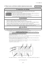
Fig.1 Part Arrangement View
2.7 Heat source unit diode module replacement procedure
It is recommended to exchange the diode module according to the following procedure.
1. Start the replacing work
ten minutes after turning off the power.
(Be sure to measure the voltage (DC)
between
the electrolytic capacitor terminals (connector terminals of fan motor power etc.) to check that
the electrolytic capacitor have been discharged completely.)
2. Disassemble the control box.
3. Disconnect the wire (G,K,AC1,AC2,AC3,+4,R5,-6 ) to the diode module. (See Fig 1.Parts Arrangement View)
4. Remove the diode module after removing the screw for diode module.
5. Attach the diode module after applying uniformly silicone grease to the back surface of the diode module.
(Recommended diode module tightening torque : 2.4 ~ 2.8N·m)
6. Connect the wire to the diode module (G,K,AC1,AC2,AC3,+4,R5,-6 ). (See Fig 1.Parts Arrangement View)
7. Assemble the control box as before.
Precautions for Safety
●
Since the following precaution is the important contents for safety, be sure to observe them.
WARNING and CAUTION are described as follows:
Indicates an imminently hazardous situation which will result in death or serious injury if
proper safety procedures and instructions are not adhered to.
Indicates a potentially hazardous situation which may result in minor or moderate injury
if proper safety procedures and instructions are not adhered to.
WARNING
●
Securely exchange the diode module according to this procedure.
If the diode module is incorrectly exchanged, it will cause an electric shock or fire.
●
Be sure to check that the power source for the outdoor unit is turned OFF before exchanging the diode
module. The diode module exchange under current-carrying will cause an electric shock.
●
After finishing the diode module exchange, check that wiring is correctly connected with the diode module before
power distribution. If the diode module is incorrectly exchanged, it will cause an electric shock or fire.
CAUTION
●
Band the wiring so as not to tense because it will cause an electric shock.
WARNING
CAUTION
PCB012D009A
(Recommended diode module tightening torque : 2.4 ~ 2.8N·m)
AC1
(Red)
AC2
(White)
AC3
(Blue)
+4
R5
-6
(From Resistor and Capacitor)
(From Capacitor and Electrolytic Capacitor)
Summary of Contents for FDC1000KXZWE1
Page 171: ... 14 KX SM 200 169 ...
Page 172: ... 14 KX SM 200 170 ...
Page 173: ... 14 KX SM 200 171 ...
Page 174: ... 14 KX SM 200 172 ...


