background image

 '14 • KX-SM-200

– 

125

 –

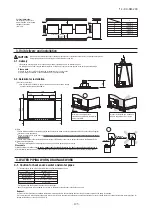
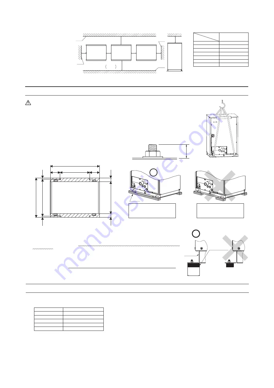
Normally, it is desirable that a
foundation as specified in the drawing
above is provided.

It cannot be installed on a foundation 
which is supported at four corners.

Base

Unit base

Vibration

isolating rubber

57

780

468

156

156

510

57

57

584

624

20

20

CAUTION

It must be installed indoors (machine room, etc.).
This unit is not designed for outdoor specifications.

MITSUBISHI HEAVY INDUSTRIES, LTD.   

WATER HEAT SOURCE MULTI AIR CONDITIONER

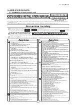
KXZW SERIES INSTALLATION MANUAL

Notabilia as a unit designed for R410A

a)
b)
c)
d)
e)

f)

g)
h)

Gauge manifold
Charge hose
Electronic scale for refrigerant charging
Torque wrench
Flare tool
Protrusion control copper pipe gauge
Vacuum pump adapter
Gas leak detector

Dedicated R410A tools

CAUTION

ACCESSORY

  ●

Please read this manual without fail before you set to installation work and carry it out according to this manual.

  ●

This unit is heat pump system only. It is not possible to be used as heat recovery system.

  ●

A heat source water circulation system is required to operate this unit.

  ●

For the installation of an indoor unit, please refer to the installation manual of an indoor unit.

  ●

For piping work, option distribution parts (branching pipe set, header set) are necessary.  Please refer to our catalog, etc.

  ●

Never fail to install an earth leakage breaker. (Please use one tolerable to harmonic components)

  ●

Operating the unit with the outlet pipe thermistor, the inlet pipe thermistor, the pressure sensor, etc. removed can result in a compressor burnout.  Avoid operation 

under such conditions in any circumstances.

  ●

With this air-conditioning system, room temperature may rise, depending on installation conditions, while indoor units are stopped, because small quantity of 

refrigerant flows into the stopped indoor units if heating operation is conducted on the system. 

COMBINATION PATTERNS

The same heat source unit is used whether it is used alone or in combination with another unit.

  ●

Please note that an installation involving a combination other than those listed below is not operable. 

● 

The possible heat source unit combinations and the number and the total capacity of indoor units that can be connected in a system are shown in the table below.

● 

Please always use indoor units designed exclusively for R410A. For connectable indoor unit model names, please check with our catalog, etc.

● 

It can be used in combination with the following indoor unit.

Name

Wiring

Instruction manual

Accessory pipe 

P224:2

P280:4

P335:1

Gasket

Reducer pipe

Quantity

2

1

1

1

Usage location

In operating the unit in the silent mode or the forced cooling/heating 
operation mode, insert it to the heat source unit board

'

s CNG.

It is supplied with the unit.  You can find 
it taped inside the control box.

Included in this installation manual set

Fixed to the drain pan in the unit with 

tapes.

When the installation work is completed,
give instructions to the customer and ask him/her to keep it.

Use for connection to high/low gas line.

Use for flange connection of the accessory pipe.

Use for connection to the heat source unit side branching pipe set on the 
unit which combines heat source units.

Attached on the top panel.

Band

4

Use to bind the power source cable to clamps.

This installation manual deals with heat source units and general installation specifications only.  For indoor units, please refer to the respective installation manuals 

supplied with your units.

Please read this manual carefully before you set to installation work and carry it out according to the instructions contained in this manual.

Designed for R410A refrigerant

Please note

a) It must be installed indoors (machine room, etc.).
b) When installing multiple units, provide sufficient intake space so that a short-circuit does not occur.
c) Do not install the equipment in areas where there is a danger for potential explosive atmosphere.

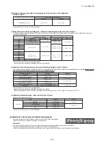
[Water quality standards]*

5

Makeup water and cyclic water shall be the water within the range of water quality standards mentioned below.
If water quality is out of the range of standards, it may cause a trouble such as scale adhesion and corrosion.

2.

INSTALLATION LOCATION

(Obtain approval from the customer when selecting the installation area.)

 Where a vent hole or air vent, capable of dissipating heat generating from the unit sufficiently, 

is provided and where ambient temperatures are within a range of 0-40˚C and humidity does 
not exceed 80%RH around the unit.

 Where the installation fittings can be firmly installed.

 Out of the heat range of other heat sources.

 A place where stringent regulation of electric noises is not applicable.

 Do not install the unit in places which:

     exposed to see breeze (e.g. coastal area) or calcium chloride (e.g. snow melting agent)
     exposed to ammonia substance (e.g. organic fertilizer)

 This heat source unit must be operated within the following limitation for use.

* Cooling tower and heating tower must be closed circuit type.
  Open circuit type could cause clogging or corrosion on the water heat exchanger in the heat source unit.

Request:

A circuit to interlock with the circulating water pump must be provided to ensure that the heat source unit operates only when the pump is operating.
It is recommended to install a water suspension relay for protection in the event when the water quantity is depleted as a result of faulty operation of valves installed on water pipe lines, air 
sucked accidentally, or other. (See Section 6-4)

*1 The fifteen items in the table represent typical causes of corrosion and scale.
*2 In a condenser water circuit that uses a closed cooling tower, the closed circuit circulating water and makeup water must satisfy its water quality standards for the hot water system and 

passing water and makeup water must satisfy those for the circulation type cooling water system.

*3 Corrosion has a tendency to occur when water temperature is high (40°C or higher), and if metals with no protective coating whatever are directly exposed to water.
     it would be a good idea to take effective measures against corrosion such as adding a corrosion inhibitor or deaeration treatment.
*4 The columns show a factor of corrosion or scale.
*5 The supply water must be clean tap water, industrial water or clean ground water.

 Where water can be drained reliably.

 Where noise will not bother nearby quiet room and neighborhood.

 A place where no TV set or radio receiver is placed within 5m.

(If electrical interference is caused, seek a place less likely to cause the problem)

 Where wind does not hinder the intake and outlet opening.

 Where strong winds will not blow against the outlet opening.

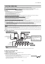
2-1. Selecting the installation location

Please secure sufficient clearance (room for maintenance work, 
passage, draft and piping).  (If your installation site does not fulfill the 
installation condition requirements set out on this drawing, please 
consult with your distributor or the manufacturer)

2-2. Installation space (service space) example

(2) Base

Please install a unit after ascertaining that the bases have been made to sufficient strength and level to ensure the unit against

vibration or noise generation.

Please construct a base to the size of a shadowed area (the entire bottom area of heat source unit

'

s base) shown on the above

drawing or larger.

Please orient a base in the traversal direction (direction of W780mm) of heat source unit as illustrated in the drawing above.

(3) Vibration isolating rubber

A vibration isolating rubber must support heat source unit

'

s base by its entire bottom area.

Please note

a) Install a vibration isolating rubber 

in such a manner that the entire bottom area of a heat source unit’s base will rest on it

.

b) Do not install a heat source unit in such a manner that a part of the bottom area of its base is off a vibration isolating rubber.

L3

L1

L5

Front side of the unit

Service

space

Wall

Wall

Wall

Wall

L4

L2

1     

600 or more

20 or more

500 or more

20 or more

300 or more

L1
L2
L3
L4
L5

Dimensions

Installation example

4. WATER PIPING WORK, DRAINAGE WORK

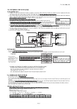
4-1. Caution for heat source water and water pipes

Precautions for safety

Never do it under any circumstances.

Always do it according to the instruction.

1. BEFORE BEGINNING INSTALLATION 

(Check that the models, power source specifications, piping, wiring are correct.)

Indoor unit 

Remote control

Connection OK/NO

FD

○△△

KXE6

RC-E3(2 cores), RC-E4(2 cores) 

OK

    RC-E5(2 cores), RC-EX1A(2 cores)

FD

A

△△

KXE4R, KXE4BR, KXE5R

RC-E1R(3 cores) 

NO

FD

A

△△

KXE4, KXE4(A), KXE4A 

RC-E1(3 cores) 

NO

Notabilia

PSC012D032

Heat source unit capacity

FDC224–1000

Read these “Precautions for safty” carefully before starting installation work and do it in the proper way.

Safety instructions listed here are grouped into        Warnings   and       Cautions.    If a non-compliant installation method is likely to result in a serious consequence such as death 

or major injury, the instruction is grouped into        Warnings  to emphasize its importance. However, a failure to observe a safety instruction listed under        Cautions     can also
result in a serious consequence depending on the circumstances. Please observe all these instructions, because they include important points concerning safety. 

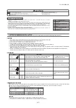
The meanings of “Marks” used here are as shown on the right:

When you have completed installation work, perform a test run and make sure that the installation is working properly. Then, explain the customer how to operate and how to take 

care of the air-conditioner according to the user’s manual. Please ask the customer to keep this installation manual together with the user’s manual.

This unit complies with EN61000-3-3. 

For heat source unit, EN61000-3-2 is not applicable as consent by the utility company or notification to the utility company is given before usage.

  ●

Do not use any refrigerant other than R410A. R410A will rise to pressure about 1.6 times higher than that of a conventional

refrigerant.

A cylinder containing R410A has a pink indication mark on the top.

  ●

A unit designed for R410A has adopted a different size indoor unit operation valve charge port and a different size check joint

provided in the unit to prevent the charging of a wrong refrigerant by mistake. The processed dimension of the flared part of a

refrigerant pipe and a flare nut's parallel side measurement have also been altered to raise strength against pressure. Accordingly,

you are required to arrange dedicated R410A tools listed in the table on the right before installing or servicing this unit.

  ●

Do not use a charge cylinder. The use of a charge cylinder will cause the refrigerant composition to change, which results in

performance degradation.

  ●

In charging refrigerant, always take it out from a cylinder in the liquid phase.

  ●

All indoor units must be models designed exclusively for R410A. Please check connectable indoor unit models in a catalog, etc. (A

wrong indoor unit, if connected into the system, will impair proper system operation)

Option parts

Refrigerant distribution piping components supplied as option parts will become necessary in installing the unit.

As refrigerant distribution piping components, branching pipe sets (model type: DOS) for the heat source unit side piping, branching pipe sets (model type: DIS) 

and header sets (model type: HEAD) for the indoor side piping are available.

Select according to the application. Please refer to Section 5-1 (4)(5).

If you are uncertain, please do not hesitate to consult with your distributor or the manufacturer.

Please use refrigerant branching sets and header sets designed exclusively for R410A without fail.

Capacity

224
280
335
450
500
560
615
670
730
775
850
900
950

1000

Combination patterns

Single
Single
Single

Combination

224+224

Combination

224+280

Combination

280+280

Combination

280+335

Combination

335+335

Combination

224+224+280

Combination

224+280+280

Combination

280+280+280

Combination

280+280+335

Combination

280+335+335

Combination

335+335+335

 Number of connectable units (units)

1

22

1

28

1

33

1

44

1

50

1

56

2

61

2

67

2

72

2

78

2

80

2

80

2

80

2

80

Range of the total capacity of indoor units connected in a system

112

336

140

420

167

503

224

672

252

756

280

840

307

923

335

1005

364

1092

392

1176

420

1275

447

1343

475

1425

502

1508

Indoor unit

Heat source unit

※ 

When connecting the indoor unit type FDK, FDFL or FDFU series, limit the connectable capacity not higher than130%.

Item

*1

Circulation system

(20°C — 60°C)

Makeup water

Makeup water

Circulation system

Cooling water system

*2

Hot water system

*3

Tendency

*4

Standard items

pH (25°C)

6.5 — 8.2

6.0 — 7.0

6.0 — 8.0

Electric conductivity (25°C)

mS/m

80

30

Chloride ion

mgCl

/L

200

50

Sulphate ion

mgSO

2

4

/L

200

50

Acid consumption (pH4.8)

mgCaCO

3

/L

100

50

Total hardness

mgCaCO

3

/L

200

70

Calcium hardness

mgCaCO

3

/L

150

50

Ionic silica

mgSiO

2

/L

50

30

Reference items

Iron

mgFe/L

1.0

0.3

Copper

mgCu/L

0.3

0.1

Sulphide ion

mgS

2–

/L

Not detected

Not detected

Ammonium ion

mgNH

4

+

/L

1.0

0.1

Residual chlorine

mgCl /L

0.3

0.3

Free carbon

mgCO

2

/L

4.0

4.0

Stability index

7.0 — 8.0

7.0 — 8.0

30

30

50

50

50

50

50

50

70

70

50

50

30

30

1.0

0.3

1.0

0.1

Not detected

Not detected

0.3

0.1

0.25

0.3

0.4

4.0

Corrosion


Scale


L3

L1

L5

Front side of the unit

Service

space

Wall

Wall

Wall

L4

1     

600 or more

20 or more

500 or more

20 or more

300 or more

20 or more
20 or more

L1
L2
L3
L4
L5
L6
L7

Dimensions

Installation example

Wall

L7

L6

L2

20

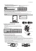
  ●

By defining a cartage path, carry in the entire package containing a unit to its installation point.

  ●

In slinging a unit, use two canvas belts with plates, cloth pads or other protections applied to the unit to prevent damage.

Please note

a) Please do not fail to put belts through the rectangular holes of a unit

'

s base.

b) Apply cloth pads between a canvas belt and a unit to prevent damage.

When a unit is hoisted with slings for haulage, please take into consideration the offset of its gravity center position.
If not properly balanced, the unit can be thrown off-balance and fall.

3-1. Delivery

(1) Anchor bolt positions

  ●

Use four anchor bolts (M10) to fix heat source unit's base at all times.  Ideally, 
an anchor bolt should protrude 20mm.

3-2. Notabilia for installation

3. 

Unit delivery and installation

CAUTION

For your information:

the footprint of heat source 
unit is 780x624 for all models 
throughout the series 
(224–335).

Item

Limitation for use

Inlet water temperature

Water pressure
Water flow rate

Water quality

Heat source water circuit

10°C – 45°C

2 MPa or less

50L/min – 150L/min

See Section 2-1 Water quality standards

Circulation type*

WARNING

CAUTION

Use the circuit breaker for all pole with correct  capacity.

Using the incorrect circuit breaker, it can cause the unit malfunction and fire.

Take care when carrying the unit by hand.

If the unit weights more than 20kg, it must be carried by two or more persons. Do not carry by the plastic straps, always use the

carry handle when carrying the unit by hand. Use gloves to minimize the risk of cuts by the aluminum fins.

Dispose of any packing materials correctly.

Any remaining packing materials can cause personal injury as it contains nails and wood. And to avoid danger of suffocation, be

sure to keep the plastic wrapper away from children and to dispose after tear it up.

Pay attention not to damage the drain pan by weld spatter when welding work is done near the indoor unit.

If weld spatter entered into the indoor unit during welding work, it can cause pin-hole in drain pan and result in water leakage. To

prevent such damage, keep the indoor unit in its packing or cover it.

Be sure to insulate the refrigerant and water pipes so as not to condense the ambient air moisture on them.

Insufficient insulation can cause condensation, which can lead to moisture damage on the ceiling, floor, furniture and any other 

valuables.

Be sure to perform air tightness test by pressurizing with nitrogen gas after completed refrigerant piping work.

If the density of refrigerant exceeds the limit in the event of refrigerant leakage in the small room, lack of oxygen can occur, which

can cause serious accidents.

Perform installation work properly according to this installation manual.

Improper installation can cause abnormal vibrations or increased noise generation.

For drain piping work, be sure to make descending slope of greater than 1/100, not to make traps and not to make air-purging. 

Check if the drainage is correctly done during test run and ensure the space for inspection and maintenance.

Be sure to take measure for anti-freezing.

Without taking measure for anti-freezing, it might cause breakage of water pipe, components or connecting joints in the system.

Be sure to perform waterproofing work and indirect wastewater treatment work

Improper treatment might cause serious damage, when water leak occurs.

Be sure to perform waterproofing work and drain work in order to prevent from the secondary damage due to the leakage

from water piping.

Before servicing the water heat exchanger and water pipes, be sure to drain water by setting the water stop valve to “close”.

There is a risk of electric shock, if water is splashed over electric parts.

Carry out the electrical work for ground lead with care.

Do not connect the ground lead to the gas line, water line, lightning conductor or telephone line's ground lead. Incorrect grounding

can cause unit faults such as electric shocks and fire due to short-circuiting. Never connect the grounding wire to a gas pipe

because if gas leaks, it could  cause  explosion  or  ignition.

Earth leakage breaker must be installed

If the earth leakage breaker is not installed, it can cause fire or electric shocks.

Do not use any materials other than a fuse with the correct rating in the location where fuses are to be used.

Connecting the circuit with copper wire or other metal thread can cause unit failure and fire.

Do not install the unit near the location where leakage of combustible gases can occur.

If leaked gases accumulate around the unit, it can cause fire.

Do not install the unit where corrosive gas (such as sulfurous acid gas etc.) or combustible gas (such as thinner and petroleum

gases) can accumulate or collect, or where volatile combustible substances are handled.

Corrosive gas can cause corrosion of heat exchanger, breakage of plastic parts and etc. And combustible gas can cause fire.

Secure a space for installation, inspection and maintenance specified in the manual. 

Insufficient space can result in accident such as personal injury due to falling from the installation place.

When the heat source unit is installed on a high place, provide permanent ladders and handrails along the access route and fences

and handrails around the heat source unit.

If safety facilities are not provided, it can cause personal injury due to falling from the installation place.

Do not install nor use the system close to the equipment that generates electromagnetic fields or high frequency harmonics

Equipment such as inverters, standby generators, medical high frequency equipments and telecommunication equipments can

affect the system, and cause malfunctions and breakdowns. The system can also affect medical equipment and

telecommunication equipment, and obstruct its function or cause jamming.

Do not install the heat source units in a location where insects and small animals can inhabit.

Insects and small animals can enter the electric parts and cause damage or fire. Instruct the user to keep the surroundings clean.

Do not use the base flame for outdoor unit which is corroded or damaged due to long periods of operation.

Using an old and damage base flame can cause the unit falling down and cause personal injury.

Do not install the unit in the locations listed below

t

Locations where carbon fiber, metal powder or any powder is floating.

t

Locations where any substances that can affect the unit such as sulphide gas, chloride gas, acid and alkaline can occur.

t

Vehicles and ships

t

Locations where cosmetic or special sprays are often used.

t

Locations with direct exposure of oil mist and steam such as kitchen and machine plant.

t

Locations where any machines which generate high frequency harmonics are used.

t

Locations with salty atmospheres such as coastlines

t

Locations where the unit is exposed to chimney smoke

t

Locations at high altitude (more than 1000m high)

t

Locations with ammonic atmospheres (e.g. organic fertilizer)

t

Locations with calcium chloride (e.g. snow melting agent)

t

Locations where heat radiation from other heat source can affect the unit

t

Locations without good air circulation.

t

Locations with any obstacles which can prevent inlet and outlet air of the unit 

t

Locations where short circuit of air can occur (in case of multiple units installation)

t

Locations where strong air blows against the air outlet of heat source unit

It can cause remarkable decrease in performance, corrosion and damage of components, malfunction and fire.

Do not install the heat source unit in the locations listed below.

t

Locations where discharged operating sound of the heat source unit can bother nearby quiet room and neighborhood.

t

Locations where outlet air of the heat source unit blows directly to an animal or plants. The outlet air can affect adversely to the plant etc.

t

Locations where vibration can be amplified and transmitted due to insufficient strength of structure.

t

Locations where vibration and operation sound generated by the outdoor unit can affect seriously.

    (on the wall or at the place near bed room)

t

Locations where an equipment affected by high harmonics is placed. (TV set or radio receiver is placed within 5m)

t

Locations where drainage cannot run off safely.

It can affect surrounding environment and cause a claim

Do not use the unit for special purposes such as storing foods, cooling precision instruments and preservation of animals, plants or

art. It can cause the damage of the items.

Do not touch any buttons with wet hands

It can cause electric shocks

Do not shut off the power source immediately after stopping the operation.

Wait at least 5 minutes, otherwise there is a risk of water leakage or breakdown.

Installation must be carried out by the qualified installer.

If you install the system by yourself, it may cause serious trouble such as water leaks, electric shocks, fire and personal injury,

as a result of a system malfunction.

Install the system in full accordance with the instruction manual.

Incorrect installation may cause bursts, personal injury, water leaks, electric shocks and fire.

Use the original accessories and the specified components for installation.

If parts other than those prescribed by us are used, It may cause fall of the unit, water leaks, electric shocks, fire, refrigerant

leak, substanard performance, contrl failure and personal injury.

When installing in small rooms, take prevention measures not to exceed the density limit of refrigerant in the event of leakage

accordance with ISO5149.

Consult the expert about prevention measures. If the density of refrigerant exceeds the limit in the event of leakage, lack of

oxygen can occur, which can cause serious accidents.

Ventilate the working area well in the event of refrigerant leakage during installation.

If the refrigerant comes into contact with naked flames, poisonous gas is produced.

After completed installation, check that no refrigerant leaks from the system. 

If refrigerant leaks into the room and comes into contact with an oven or other hot surface, poisonous gas is produced. 

Hang up the unit at the specified points with ropes which can support the weight in lifting for portage. And to avoid jolting out

of alignment, be sure to hang up the unit at 4-point support.

An improper manner of portage such as 3-point support can cause death or serious personal injury due to falling of the unit.

Install the unit in a location with good support.

Unsuitable installation locations can cause the unit to fall and cause material damage and personal injury.

Ensure the unit is stable when installed, so that it can withstand earthquakes and strong winds.

Unsuitable installation locations can cause the unit to fall and cause material damage and personal injury.

The electrical installation must be carried out by the qualified electrician in accordance with "the norm for electrical work"

and "national wiring regulation", and the system must be connected to the dedicated circuit.

Power source with insufficient capacity and incorrect function done by improper work can cause electric shocks and fire.

Be sure to shut off the power before starting electrical work. 

Failure to shut off the power can cause electric shocks, unit failure or incorrect function of equipment.

Be sure to use the cables conformed to safety standard and cable ampacity for power distribution work. 

Unconformable cables can cause electric leak, anomalous heat production or fire.

Use the prescribed cables for electrical connection, tighten the cables securely in terminal block and relieve the cables

correctly to prevent overloading the terminal blocks.

Loose connections or cable mountings can cause anomalous heat production or fire.

Arrange the wiring in the control box so that it cannot be pushed up further into the box. Install the service panel correctly.

Incorrect installation may result in overheating and fire.

In connecting the power cable, make sure that no anomalies such as dust deposits, socket clogging or wobble are found and

insert the plug securely.

Accumulation of dust, clogging on the socket, or looseness of plugging can cause electric shocks and fire.

Be sure not to reuse existing refrigerant pipes

Conventional refrigerant oil or chlorine contained in the conventional refrigerant which is remaining in the existing refrigerant

pipes can cause deterioration of refrigerant oil of new unit. And 1.6 times higher pressure of R410A refrigerant than

conventional one can cause burst of existing pipe, personal injury or serious accident.

Do not perform brazing work in the airtight room

It can cause lack of oxygen.

Use the prescribed pipes, flare nuts and tools for R410A.

Using existing parts (for R22 or R407C) can cause the unit failure and serious accidents due to burst of the refrigerant circuit.

Tighten the flare nut by using double spanners and torque wrench according to prescribed method. Be sure not to tighten the

flare nut too much. 

Loose flare connection or damage on the flare part by tightening with excess torque can cause burst or refrigerant leaks

which may result in lack of oxygen. 

Do not open the service valves for liquid line and gas line until completed refrigerant piping work, air tightness test and

evacuation.

If the compressor is operated in state of opening service valves before completed connection of refrigerant piping work, you

may incur frost bite or injury from an abrupt refrigerant outflow and air can be sucked into refrigerant circuit, which can cause

burst or personal injury due to anomalously high pressure in the refrigerant.

Do not put the drainage pipe directly into drainage channels where poisonous gases such as sulphide gas can occur.

Poisonous gases will flow into the room through drainage pipe and seriously affect the user's health and safety. It can also

cause the corrosion of the indoor unit and resultant unit failure or refrigerant leak.

Only use prescribed option parts. The installation must be carried out by the qualified installer.

If you install the system by yourself, it can cause serious trouble such as water leaks, electric shocks, fire.

Do not perform any change of protective device itself or its setup condition

The forced operation by short-circuiting protective device of pressure switch and temperature controller or the use of non

specified component can cause fire or burst.

Be sure to switch off the power source in the event of installation, inspection or servicing.

If the power source is not shut off, there is a risk of electric shocks, unit failure or personal injury due to the unexpected start

of fan.

Consult the dealer or an expert regarding removal of the unit. 

Incorrect installation can cause water leaks, electric shocks or fire.

Stop the compressor before closing valve and disconnecting refrigerant pipes in case of pump down operation.

If disconnecting refrigerant pipes in state of opening service valves before compressor stopping, you may incur frost bite or

injury from an abrupt refrigerant outflow and air can be sucked, which can cause burst or personal injury due to anomalously

high pressure in the refrigerant circuit.

Ensure that no air enters in the refrigerant circuit when the unit is installed and removed.

If air enters in the refrigerant circuit, the pressure in the refrigerant circuit becomes too high, which can cause burst and

personal injury.

Do not run the unit with removed panels or protections

Touching rotating equipments, hot surfaces or high voltage parts can cause personal injury due to entrapment, burn or

electric shocks.

Be sure to fix up the service panels.

Incorrect fixing can cause electric shocks or fire due to intrusion of dust or water. 

Do not perform any repairs or modifications by yourself. Consult the dealer if the unit requires repair. 

If you repair or modify the unit, it can cause water leaks, electric shocks or fire.

CAUTION

Do not control the system with main power switch.

It can cause fire or water leakage. In addition, the fan can start unexpectedly, which can cause personal injury.

Do not touch any refrigerant pipes with your hands when the system is in operation.

During operation the refrigerant pipes become extremely hot or extremely cold depending the operating condition, and it can cause

burn injury or frost injury.

Do not operate the heat source unit with any article placed on it.

You may incur property damage or personal injure from a fall of the article.

Do not step onto the heat source unit.

You may incur injury from a drop or fall.

CAUTION

Please ventilate sufficiently this installation space.

Summary of Contents for FDC1000KXZWE1

Page 1: ...ERTER MULTI SYSTEM AIR CONDITIONERS KXZW Heat source units Single use Used also for combination FDC224KXZWE1 280KXZWE1 335KXZWE1 Combination use FDC450KXZWE1 500KXZWE1 560KXZWE1 615KXZWE1 670KXZWE1 730KXZWE1 775KXZWE1 850KXZWE1 900KXZWE1 950KXZWE1 1000KXZWE1 Water cooled series SERVICE MANUAL updated March 30 2018 ...

Page 2: ...Explanation of troubleshooting 57 2 3 Contents of troubleshooting 58 2 4 Heat source unit control PCB replacement procedure 113 2 5 Heat source unit inverter PCB replacement procedure 115 2 6 Heat source unit transistor module replacement procedure 117 2 7 Heat source unit diode module replacement procedure 118 3 ELECTRICAL WIRING 120 4 PIPING SYSTEM 121 5 APPLICATION DATA 122 5 1 Installation of ...

Page 3: ... set temp button Displays the temperature which is set currently Tap this button to change the set temperature Change operation mode button Displays the operation mode which is selected currently Tap this button to change the operation mode Timer button Displays simplified contents of the timer which is set currently When two or more timers are set contents of the timer which will be operated imme...

Page 4: ...ent mode Cover AIR CON No button Display the indoor unit number connected to this remote control CHECK button This button is used at servicing TEST button This button is used during test operation Weekly timer display Displays the settings of the weekly timer Operation setting display area Displays setting temperature airflow volume operation mode and oparation message Operation check indicator li...

Page 5: ...n this is pressed once again it stops operating Used to swing the louver Every time this button is pressed displays switch as below Sets room temperature by pressing or button Sets time when setting the time Used to cancel the TIMER SETTINGS Used to reset the microcomputer Indicates the selected airflow volume Indicates when ON TIMER is set Indicates the ON TIMER setting time Nothing displayed whe...

Page 6: ...rd 4 digit number TOP screen Menu screen 1 Menu screen 3 Service password input Tap the Menu button on the TOP screen Main menu screen is displayed Tap the Service Maintenance on the menu screen Display the service password input screen Enter the service password 4 digit number TOP screen Menu screen 1 Menu screen 3 Service password input Service maintenance menu 1 Service maintenance menu 2 Servi...

Page 7: ...etting of silent mode is cancelled regardless whether the power failure compensation is effective or not a At power failure Operating stopped If it had been operating under the off timer mode sleep timer mode the state of stop is memorized Although the timer mode is cancelled at the recovery from power failure the setting of weekly timer is changed to the holiday setting for all weekdays b Operati...

Page 8: ... After the elapse of the set time period the current set temp will be set back to the Set back temp The setting can be done in cooling and heating mode respectively The selectable range of the set time is from 20 min to 120 min 10 min interval Set the Set back temp by 1 interval 6 Filter sign reset メ ニュー 7番目 A 1 Filter sign reset B 2 Setting next cleaning date A 7 Initial settings メ ニュー 8番目 1 Cloc...

Page 9: ...n speed setting Valid or Invalid of Auto fan speed setting can be selected B B B B B A A A A Main indoor unit address can be set Only the Main indoor unit can change operation mode and the Sub indoor units dominated by the Main indoor unit shall follow The Main indoor unit can domain 10 indoor units at a maximum 12 Installer settings 13 RC function settings Setting display item 11 Administrator se...

Page 10: ...e of stop is memorized Although the timer mode is cancelled at the recovery from power failure the setting of weekly timer is changed to the holiday setting for all weekdays b Operation mode c Airflow volume mode d Room temperature setting e Louver auto swing stop However the stop position 4 position is cancelled so that it returns to Position 1 f Remote control function items which have been set ...

Page 11: ...it fan tap at the thermostat ON is retained so far as the thermostat is turned OFF 3 Timer operation a RC EX1A i Sleep timer Set the time from the start to stop of operation The time can be selected in the range from 30 to 240 minutes in the unit of 10 minute Note 1 Enable the Sleep timer setting from the remote control If the setting is enabled the timer operates at every time ii Set OFF timer by...

Page 12: ...n parallel when the times to turn ON and OFF the air conditioner are duplicated the set ting of the OFF timer has priority 4 Remote control display during the operation stop When the operation is stopped the power supply is turned ON it displays preferentially the Room temperature Center Remote Filter sign Inspection and Timer operation 5 Hot start Cold draft prevention at heating a Operating cond...

Page 13: ... the indoor heat exchanger temperature detected with ThI R1 or R2 drops to 35 C or lower the speed of indoor fan is changed to the lower tap at each setting ii During the hot keep the louver is kept at the horizontal position b Ending condition When the indoor fan is at the lower tap at each setting it returns to the set airflow volume as the indoor heat exchanger temperature rises to 45 C or high...

Page 14: ...vent the cold start The louver position display LCD continues to show the display which has been shown before entering this control iii Louver free stop control When the louver free stop has been selected with the indoor function of wired remote control POSITION the louver motor stops when it receives the stop signal from the remote control If the auto swing signal is received from the remote cont...

Page 15: ... including stop this control is stopped immediately and the operating condition is restored v When the Fan OFF is selected the fan on the indoor unit of which the thermostat has been turned OFF is turned OFF The same occurs also when the remote control sensor is effective d Fan control during cooling thermostat OFF i Following fan controls during the cooling thermostat OFF can be selected with the...

Page 16: ...s after the compressor ON 1 OFF OFF 3 minutes delay Thermostat OFF in the condition of 9 Compressor Indoor unit A Thermostat Indoor unit B Thermostat 11 Drain pump control a This control is operated when the inverter frequency is other than 0 rps during the cooling operation and automatic cooling and dehumidifying operations b Drain pump ON condition continues for 5 minutes even when it enters the...

Page 17: ...ng on each operating condition 13 Operation check drain pump test run operation mode a If the power is turned on by the dip switch SW7 1 on the indoor PCB when electric power source is supplied it enters the mode of operation check drain pump test run It is ineffective prohibited to change the switch after turning power on b When the communication with the remote control has been established withi...

Page 18: ...s E6 18 External input output control CnT or CnTA Be sure to connect the wired remote control to the indoor unit Without wired remote control remote operation by CnT is not possible to perform CnT CnTA Operation output CnT 2 XR1 Heating output CnT 3 XR2 Thermostat ON output CnT 4 XR3 Error output CnT 5 XR4 Remote operation input CnT 6 Volt free contact XR1 1 2 3 4 5 6 XR3 XR4 CnT Blue 12V XR2 Opti...

Page 19: ...e indoor function setting of Level input Factory default or Pulse input is selected by the function for External input of the wired remote control operation status will be changed as follows i In case of Level input setting Factory default Input signal to CnT 6 or CnTA is OFF ON unit ON Input signal to CnT 6 or CnTA is ON OFF unit OFF Operation is not inverted ON ON OFF OFF OFF ON ON ON ON Remote ...

Page 20: ...key switch is ON CnT 6 or CnTA ON Operation permission start stop operation of the unit from the wired remote control becomes available When card key switch is OFF CnT 6 or CnTA OFF Operation prohibition the unit stops operation in conjunction with OFF signal and start stop operation of the unit from the wired remote control becomes not available 2 In case that Operation permission prohibition mod...

Page 21: ...e input is set for the indoor unit function If the external input is changed OPEN CLOSE operation modes are inverted Cooling Heating or Heating Cooling Operation Operation Operation Stop Stop Stop Stop Operation prohibition Operation prohibition Operation prohibition Operation prohibition Operation prohibition Operation prohibition Operation permission Operation permission Operation permission Ope...

Page 22: ...is installed at the ceiling where warm air tends to accumulate the setting can be changed with the wired remote control indoor unit function The compressor and the heater are turned ON OFF at one of the setting temperature 3 2 or 1 C in order to improve the feeling of heating The setting temperature however has the upper limit of 30 C Compressor Compressor Standard Operation Stop Setting temperatu...

Page 23: ...wer than 25 C unit goes thermo OFF 30 Auto fan speed control RC EX1A only In order to reach the room temperature to the set temperature as quickly as possible the airflow rate is increased when the set temperature of thermostat differs largely from the return air temperature According to temperature difference be tureen set temperature and return air temperature indoor fan tap are controlled autom...

Page 24: ...tandard models of 2 pipe system the heat source unit operation mode of Stop Cooling Heating is selected based on the information of indoor units and then respective controls are performed Contents of control a Determination of heat source unit operation mode Operation mode of heat source unit is determined based on respective signals of Operation Stop and Cooling Heating The compressor however sta...

Page 25: ...peration lamp flickers Fan ON Indoor unit 0 Stop Cooling Heating Invalid operation lamp flickers Fan ON ON Indoor unit 1 Stop Cooling Cooling ON When it is changed from same mode to unmatch Operation mode is prepared for change in the fan mode Last unit s operation mode If the indoor unit 1 of which operation mode is different has joined in when the indoor units 0 is operating 5 Reset of unmatched...

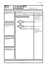
Page 26: ... units running It is able to make the emergency stop function effective by remote control indoor function setting a When the heat source unit receives the Emergency stop command from the indoor unit it makes all stop by error b And the Emergency stop command is transmitted to all indoor units and error code E63 is displayed c When the heat source unit receives the Emergency stop reset command from...

Page 27: ... for each heat source unit is set depending on the number of heat source units Set the start order as shown in the following table starting from the first in the heat source unit start order When the power is turned on the master unit is given the position of the first in the heat source unit start order Pattern at the combination of 3 heat source units Pattern Start order A 1 A 2 A 3 B 1 B 2 B 3 ...

Page 28: ... to the end of 4 way valve switching and the completion of preparation for compres sor rpm UP Status 2 After the end of Status 1 to the establishment of defrost end condition Status 3 From the end of Status 2 to the compressor rpm DOWN c Ending condition When one of the following conditions is established At the end of the defrost status 3 When the heat source unit operation mode has changed to an...

Page 29: ... ii If the above control activates 4 times within 15 minutes 52C1 is turned off and the operation is stopped with the error stop State of the error continues for 3 minutes after the error stop The error can be reset by operating the inspection reset from the remote control g Power transistor temperature PT protective control If temperatures on the power transistor exceed the setting value the comp...

Page 30: ... of CnS1 S2 input method CnS1 S2 only J13 shorted Level input by CnS1 S2 J13 open Pulse input by CnS1 S2 1 Setting means Master Set only the master unit No necessary to set the slave unit Master Slave Set both master slave unit same External input terminal External input function allotment of 7 segment Terminal Specification Factory setting Code Function No Factory setting CnS1 No voltage contact D...

Page 31: ...ol b Demand control Note Following explanation is based on using CnS2 terminal and setting function P08 1 with 7 segment display However other terminals can be used with following function setting of 7 segment display CnS1 P07 1 CnG1 P09 1 CnG2 P10 1 1 Demand control or normal control is switched with the connector CnS2 and the jumper wire J13 on the heat source unit control PCB after setting func...

Page 32: ... OFF ON ON Demand OFF OFF ON ON ON ON OFF OFF Demand This control has priority over the controls of 4 way valve safeguard compressor protective start operation defrost operation oil equalized operation oil return operation pump down operation for replacement Start Stop pump down operation and check operation 2 Demand control Normal operation by the external input CnS2 to heat source unit Note 1 Fa...

Page 33: ... step demand input via the external input terminal of heat source unit master unit has become valid 2 Contents of control The demand control is performed at the demand rate which has been set with SW4 5 SW4 6 and P04 according to the demand input or the 2 step demand input Demand control Following is assigned to one of P07 P10 Demand rate setting Demand input Function assignment 1 2 step demand in...

Page 34: ...thernistor anomaly E 1 Power transister overheat Continuousness E Outdoor air temperature thermistor anomaly E Suction pipe temperature thermistor anomaly E Under dome temperature thermistor anomaly E Discharge pipe temperature thermistor anomaly E 0 High pressure anomaly E Power transitor temperature thermistor anomaly E 1 Power transister overheat E Anomalous compressor by loss synchronism E Cur...

Page 35: ... limit value d Control after the conditions to prohibit the auto backup operation have been established All compressor stop and the error display E XX is shown on the segment display and the remote control In this state the inspection reset of remote control is effective E XX is displayed continuously on the remote con In this state the inspection reset of remote control is effective E XX is displ...

Page 36: ...However regarding the dip switch SW3 2 for automatic backup operation it is invalid during test run operation regardless whether SW3 2 is turned ON valid or OFF invalid In order to check trouble during test run operation d Control during test run If indoor units are normal i Heating operation is performed with SW5 2 OFF while cooling operation is performed with SW5 2 ON ii Indoor EEV control at th...

Page 37: ...d in the field The maximum load of relay is LY2F Omron f The output connectors CnH CnY to be connected to the relays for operation output 52XR and for error output 52XE is mounted on the heat source unit control PCB g If CPU goes out of control this function becomes disable h When the automatic backup operation is effective there is no error display for any error on the compressor stopping by dete...

Page 38: ...rmed with the operation of 3 dip switches SW5 1 Test run switch SW5 2 Test run operation mode and SW5 3 Pump down switch c Pump down procedure 1 Shut the liquid side service valve on the heat source units 2 Turn SW5 2 test run operation mode ON cooling 3 Turn SW5 3 pump down switch ON 4 Turn SW5 1 test run switch ON d End condition If any of the following conditions is satisfied this control ends ...

Page 39: ...h the thermostat ON a Correction of target high low pressure i Starting condition either of or When the external input function assignment P07 P10 Multi system energy save control Valid When 7 segment P69 Multi system energy save control I ON if the external input function assignment P07 P10 is not assigned this control ii Contents of control During the heat source unit operation mode at cooling I...

Page 40: ... in the order of 0 1 2 9 0 8 If SW9 order of 10 is pressed it jumps to the leading code of each order of 10 Example If SW9 is pressed at the code No C07 displayed it jumps to the code No C10 If SW9 is pressed 9 The data of code No C44 and C45 can be erased independently The compressor cumulative operation time corresponding to the code No selected can be erased reset For resetting of the compresso...

Page 41: ... SC During heating mode this data might be unreliable as sub cooling degree but the result is displayed as it is C50 Suction superheat degree Suction pipe temperature C detected with suction pipe temperature thermistor Tho S Low pressure saturated temperature C detected with low pressure sensor PLS C51 Superheat degree of sub cooling coil Sub cooling coil temperature C detected with sub cooling co...

Page 42: ...cooling coil PSL Low pressure sensor CM1 operating frequency Exx oPx oPE X PdS PdE CH CHF CO HE PCL dLP PSH High pressure sensor C30 0 1 63H1 1 í Order of 100 63H1 1 Order of 10 Spare 0 Close 1 Open 14 KX SM 200 Opening angle of EEVW1 expansion valve for water heat exchanger 1 Opening angle of EEVW2 expansion valve for water heat exchanger 2 Opening angle of EEVG expansion valve for high pressure ...

Page 43: ...pare Order of 1 Spare 0 Close 1 Open 0 Close 1 Open Order of 100 SV4 Order of 10 SVO Order of 1 Spare CNZ1 CNH CNY Number of connected indoor unit 0 80 1 Capacity ratio of connected indoor unit 0 999 1 Number of operation indoor unit 0 50 Required Fk total 0 999 1Hz Compressor cumulative operating time CM1 0 655 100h Discharge pressure saturation temperature 50 70 0 1 C Suction pressure saturation...

Page 44: ... cut CM1 0 255 1 EEPROM memory Resettable Counter Power transistor overheat CM1 Counter Compressor startup failure CM1 Counter Anomalous compressor by loss of synchronism CM1 Counter Communication error between inverter PCB and heat source unit control CM1 0 255 0 255 0 255 0 255 0 255 1 1 1 1 EEPROM memory Resettable EEPROM memory Resettable EEPROM memory Resettable EEPROM memory Resettable EEPRO...

Page 45: ...able number of indoor units for each heat source unit 14 KX SM 200 0 Factory default 0 1 C66 Control status Definition of signal Shows the status of control in operation currently If two or more controls among the following protection controls are established simultaneously No of the control of which number is larger is displayed Protection control status Number Ordinary control Remote control all ...

Page 46: ...omalous compressor by loss of synchronism CM1 40 Communication error between the master unit and slave units 42 Compressor stop by special Operation mode change 50 Differential pressure startup prevention control 51 Protect for heating overload 52 Spare 53 14 KX SM 200 C67 Protection control status Definition of signal Shows the status of protection control in operation currently If two or more con...

Page 47: ... purpose to investigate the cause of trouble in the field the operation data are always saved in thememory and if the trouble occurs the data writing is stopped and the operation data prior to the trouble occurrence are recorded These data can be retrieved to personal computer through RS232C connector on the heat source unit control PCB and utilized for probing the cause i Operation data for a peri...

Page 48: ...ed 02 20 70 Tho A Outdoor air temp Cooling liquid side Cooling gas side 03 04 40 75 40 75 2 2 Tho R1 Heat exchanger temp 1 Tho R2 Heat exchanger temp 2 07 09 20 140 30 90 2 2 Tho D1 Discharge pipe temp CM1 Tho C1 Under dome temp CM1 11 20 140 Tho P1 Power transistor temp Heat dissipation fin 13 40 75 Tho S Suction pipe temp 14 40 75 Tho SC Sub cooling coil temp 1 Heat source unit indicate data Hea...

Page 49: ...mode 31 0 255 1 1 Heat source unit operation pattern Real range is 1 17 32 0 255 1Hz 1 CM1 frequency 37 50 70 2 Discharge pressure saturation temp 0 01 C 38 50 30 2 Intake pressure saturation temp 0 01 C 39 1 0 10 0 0 1 Pressure ratio 40 41 42 0 25 5 0 25 5 0 25 5 0 1deg 1 1 1 Cooling operation sub cooling Super heat of suction pipe Super heat of sub cooling coil 14 KX SM 200 0 001MPa 2 0 001MPa 2...

Page 50: ...t super heat of water heat exchanger Countdown of refrigerant oil return 1 63 1 Output of relay 64 1 Output of relay Bit1 Bit2 Bit3 Bit4 Bit5 Bit6 Bit7 Bit0 Bit1 Bit2 Bit3 Bit4 Bit5 Bit6 Bit7 Bit0 Bit1 Bit2 Bit3 Bit4 Bit5 Bit6 Bit7 Spare 52C2 CH1 Spare CH2 20SM 20SH FMC1 2 Spare FMC3 SVB Spare SV2 SVR SVO Spare SV7 SVA Spare SV10 Spare SV11 Spare SV12 Spare SV13 Spare SV3 Spare Spare CNZ1 CnH CnY ...

Page 51: ...ualized operation 4 2 Oil equalized operation 5 1 Oil equalized operation 5 2 Oil equalized operation 6 1 Oil equalized operation 6 2 Oil equalized operation 7 1 Oil equalized operation 7 2 Oil equalized operation 8 1 Oil equalized operation 8 2 None Oil return cooling 0 1 10 20 30 41 42 51 52 61 62 71 72 81 82 0 1 2 0 2 1 Control status Defrost kinds defrost status Control status Oil return Oil r...

Page 52: ...Count 1 Count up 0 Count 1 Count up 0 Count 1 Count up 81 0 127 1hour 1 Backup cumulative time 82 0 7 1 Check operation status 83 Spare Bit0 Bit1 Bit2 Bit3 Bit4 Bit5 Bit6 Bit7 0 Normal 1 Practice 0 Normal 1 Practice 0 Normal 1 Practice 0 Normal 1 Practice 0 Normal 1 Practice 0 Normal 1 Practice 0 Normal 1 Practice 0 Normal 1 Practice Td protection 2 1 EEVSC Td cooling control Td protection 4 Heati...

Page 53: ...r transistor overheat CM1 104 105 0 255 Counter Compressor startup failure CM1 106 107 0 255 Counter Anomalous compressor by loss of synchronism CM1 108 109 0 255 Counter Communication error between inverter PCB and heat source unit control CM1 110 111 14 KX SM 200 0 Normal 1 Practice 0 Normal 1 Practice 0 Normal 1 Practice 0 Normal 1 Practice 0 Normal 1 Practice PT protection 1 PT protection 2 In...

Page 54: ... 1 External input 52P a CNS1 CNS2 CNG1 CNG2 125 1 DIP SW SW3 SW3 1 SW3 2 SW3 3 SW3 4 SW3 5 SW3 6 SW3 7 SW3 8 126 1 DIP SW SW4 SW4 1 SW4 2 SW4 3 SW4 4 0 OFF 1 ON 0 OFF 1 ON 0 OFF 1 ON 0 OFF 1 ON 0 OFF 1 ON 0 OFF 1 ON 0 OFF 1 ON 0 OFF 1 ON 0 OFF 1 ON 0 OFF 1 ON 0 OFF 1 ON 0 OFF 1 ON 0 OFF 1 ON 0 OFF 1 ON 0 OFF 1 ON 0 OFF 1 ON 0 OFF 1 ON 14 KX SM 200 Bit6 Bit7 Spare Spare 0 OFF 1 ON 0 OFF 1 ON 1 112 ...

Page 55: ...R ĺ RQO 141 Override 14 KX SM 200 Bit4 Bit5 Bit6 Bit7 SW4 5 SW4 6 SW4 7 SW4 8 Bit0 Bit1 Bit2 Bit3 127 1 DIP SW SW5 SW5 1 SW5 2 SW5 3 SW5 4 0 OFF 1 ON 0 OFF 1 ON 0 OFF 1 ON 0 OFF 1 ON Bit4 Bit5 Bit6 Bit7 SW5 5 SW5 6 SW5 7 SW5 8 0 OFF 1 ON 0 OFF 1 ON 0 OFF 1 ON 0 OFF 1 ON 0 OFF 1 ON 0 OFF 1 ON 0 OFF 1 ON 0 OFF 1 ON Bit0 Bit1 Bit2 Bit3 128 1 DIP SW SW6 SW6 1 SW6 2 SW6 3 SW6 4 Bit4 Bit5 Bit6 Bit7 SW6 ...

Page 56: ...g order of 1 7 segment display code No increasing order of 10 Model selection Demand control Master slave unit setting address Power source voltage selection External input Level Pulse See following table Note 1 Jumper wires J13 indicate short circuit open 2 Dip switch SW s indicate OFF ON 3 indicates the factory setting OFF Code Input Remarks SW6 1 Hz fixed mode selection Normal Hz fixed 14 KX SM...

Page 57: ... SW7 3 OFF Spare SW7 4 OFF Reserved JSL1 With Superlink terminal spare SW7 2 OFF Reserved Model selection As per model Automatic Previous SL Normal Normal 0 Automatic Remarks Indoor unit address No Order of 10 Indoor unit address No Order of 1 Heat source unit address No Order of 10 Heat source unit address No Order of 1 Superlink selection Indoor unit address No Order of 100 0 9 0 9 0 9 0 9 Code ...

Page 58: ...ping or wiring etc Is the failure related to any hardware parts SV main body coil capillary check valve sensor etc Is it a major component Compressor inverter PCB Is it a failure of electrical component Error on indoor unit or heat source unit Indoor unit Heat source unit Is the remote control connected Was the power source reset after the error occurred Check and write down the momentary data ret...

Page 59: ...r OFF Even if DC15V is detected go to further diagnosis of E41 E42 E45 sequentially Turn the power ON power circuit breaker ON and start operation with the test run SW Check between 1 and 2 of CNI1 on the control PCB to see if DC15V is detected Be sure to wait for 3 minutes after turning the power circuit breaker off Since unless DC15V is detected faulty inverter PCB is suspected check CNI1 at the...

Page 60: ...e unit address No Address setting error 92 E32 E32 Open L3 Phase on power source at primary side Site setting error 93 E36 E36 1 Discharge pipe temperature error Tho D1 System error 94 E37 E37 1 2 E37 5 6 Heat source unit heat exchanger temperature thermistor Tho R1 R2 and sub cooling coil temperature thermistor Tho SC H anomaly Thermistor wire breakage 95 E38 E38 Atmosphere air temperature thermi...

Page 61: ...This unit is designed to start in the soft start mode by detecting the compressor under dome temperature when it restart after power reset It is necessary to replace to higher capacity unit or to install additional unit Compressor refrigerant oil protective control at starting is activated For the contents of control refer to the compressor start control Compressor may be stopped by the error dete...

Page 62: ...g or heating operation from remote control Note 1 Outdoor 7ºC Indoor 20ºCDB It is normal This unit is designed to start in the soft start mode by detecting the compressor under dome temperature when it restart after power reset It is necessary to replace to higher capacity unit or to install additional unit Compressor refrigerant oil protective control at starting is activated For the contents of ...

Page 63: ...urce the insulation resistance may drop to a few M Ω because of refrigerant migrated in the compressor When the earth leakage breaker is activated at lower insulation resistance check the following points 6 hours after power ON check if the insulation resistance recovers to normal When power ON crankcase heater heat up compressor and evaporates the refrigerant migrated in the compressor Check if t...

Page 64: ...to eliminate looseness Prevent the vibration from transmitting to wall and etc by fixing pipes on the wall tightly or wrapping rubber cushion around the pipe which goes through the hole in the wall or applying other appropriate means Strength of ceiling wall floor etc may be insufficient Review the installation place or apply reinforcement to increase the strength Check for leaning of installed un...

Page 65: ... gas or liquid flows through inside of piping of air conditioner It is likely to occur particularly during cooling or defrosting in the heating mode It is normal The noise vibration occurs when the refrigerant starts or stops flowing It is normal When the defrosting starts or stops during heating mode the refrigerant flow is reversed due to switching 4 way valve This causes a large change in press...

Page 66: ...erant Intrusion of air nitrogen etc In such case it is necessary to recover refrigerant vacuum dry and recharge refrigerant Since there could be many causes of noise vibration the above may not cover all In such case check the conditions when where how the noise vibration occurs according to following check points and ask our consultation Indoor heat source unit Cooling heating fan mode Startup st...

Page 67: ... flow setting YES NO Does the louver link press LS till crick sound can be heard NO NO YES NO NO YES In cases of FDTW FDTS and FDTQ Does the louver operate when power on Note 1 LM Louver motor 2 LS Limit switch YES NO NO NO NO YES YES Operate after waiting for more than 1 minute It is normal if LM can be stopped by pressing LS two times In cases of FDT FDTC FDE and FDK Check the remote control whe...

Page 68: ...ower source between of CNW0 OK Is DC5V detected between of CNW2 Is power source to FM LM and etc OK Note 1 Check the fuse at the power source side 1 2 3 4 Model equipped with transformer Tr 㧵 Models other than shown at left Is DC18V or higher detected between Red Red CNW2 at the transformer secondary side Heat source unit Noise filter PCB anomaly Replace it Wrong wiring or broken wires between hea...

Page 69: ... secondary side Is DC18V detected between of CNW2 Disconnect the remote control wires NO Is DC15V or higher detected between X Y of indoor unit terminal block Model equipped with transformer Tr㧵 Models other than shown at left YES YES YES YES NO NO YES NO NO Correct it Replace wires Replace remote control Indoor power PCB anomaly Replace it Indoor control PCB anomaly Replace it Replace transformer...

Page 70: ...eplace noise filter PCB Connect wires correctly Indoor control PCB anomaly Replace it Indoor heat source unit control PCB anomaly Replace it Remote control anomaly Replace it Breakage of wires for remote control Replace it Correct the connecting wires between indoor and heat source units Heat source unit control PCB anomaly Replace it Breakage of connecting wire Noise Indoor control PCB anomaly Re...

Page 71: ...YES NO Isn t there any short circuit between phases of noise filter Isn t there any crack or damage on power transistor module or diode stack Isn t there any anomaly on reactor Replace noise filter Replace reactor Replace inverter PCB Replace fuse 2 Error detection method 3 Condition of error displayed 4 Presumable cause Fuse blown Noise filter anomaly Anomalous connection of wire between PCBs Ind...

Page 72: ...nal block Is The fuse on indoor control PCB OK Is AC18V or higher is detected between Red Red at secondary side of indoor transformer 1 Is DC10 11V between X Y at indoor control PCB side when removing remote control Note 1 Model equipped with transformer Tr㧵 only Fuse blown Replace fuse Transformer anomaly Remote control wire short circuited Remote control anomaly Indoor control PCB anomaly Remote...

Page 73: ... 415V detected between L1 L2 L2 L3 L3 L1 respectively at heat source unit terminal block Is AC220 240V detected between L N at indoor terminal block NO NO NO NO NO YES YES YES YES YES YES A Refer next page WAIT Indoor control PCB anomaly Replace it Indoor control PCB anomaly Replace it Remote control anomaly Replace it Breakage of wires for remote control Replace it Correct the connecting wires be...

Page 74: ... the connection of connecting wire of reactor OK Once turn OFF the breaker and turn ON it again at 3 minutes after power OFF Does it become normal Check inverter before replacement of 52C NO NO NO NO NO YES YES YES YES YES A B Refer next page From previous page Normal Malfunction by temporary noise Replace noise filter Connect the connecting wire properly Correct connection In case of breakage of ...

Page 75: ...e Replace electrolytic capacitor Replace reactor Isn t there any short circuit between phases at input terminal of inverter PCB Isn t there any crack or damage on power transistor module or diode stack Isn t there any anomaly on reactor Isn t there any anomaly on electrolytic capacitor NO NO NO NO NO B YES YES YES YES YES From previous page 2 Error detection method 3 Condition of error displayed 4...

Page 76: ... detected at remote control terminal Is DC10V or higher between X Y wires detected when removing remote control Are connecting wires between indoor and heat source units connected properly Remote control anomaly Remote control anomaly Correct connecting wire Indoor control PCB anomaly 2 Error detection method 3 Condition of error displayed 4 Presumable cause Fuse blown Noise filter anomaly Anomalo...

Page 77: ... 1 OFF ON Note 2 Does the remote control displays Internal check ON even after 3 minutes Reset power source 2 1 NO Malfunction by temporary noise Check peripheral environment Indoor control PCB anomaly Replace it Remote control anomaly Replace it 2 Error detection method When normal communication between remote control and indoor unit is interrupted for more than 2 minutes Detectable only with the...

Page 78: ...e power source is reset addresses will not be confirmed YES NO YES NO YES NO Review number of connected units Correct indoor unit address setting Implement test run Replace indoor control PCB Before replacement confirm whether the rotary switch for address setting is not damaged It was experienced that No 5 on rotary switch was not recognized 2 Error detection method More than 129 indoor units are...

Page 79: ... to E5 In both cases check signal line wired locally YES Is the heat source unit address set on the indoor unit OK YES Is the LED on indoor control PCB OK YES Is protective fuse for the Superlink circuit blown NO Does E3 E5 occurs YES NO NO NO YES YES NO NO Temporary malfunction by noise Identify the source of noise and correct it Change to spare circuit Indoor control PCB anomaly Replace it Corre...

Page 80: ...ness breakage of signal wires between indoor and heat source units YES NO YES NO YES NO In case that indoor red LED flashes 2 times Repair signal wires Repair signal wires Go to the diagnosis of WAIT 1 Unit is normal Malfunction by temporary noise etc Heat source unit control PCB anomaly Network communication circuit anomaly Replace it Unit is normal Malfunction by temporary noise etc 2 Error dete...

Page 81: ...ture resistance characteristics of indoor heat exchanger temperature thermistor ThI R1 R2 R3 5kΩ at 25ºC Temperature ºC Insert the connector securely Replace thermistor ThI R Replace indoor control PCB 2 Error detection method Detection of anomalously low temperature resistance of ThI R1 R2 R3 3 Condition of error displayed If 50ºC or lower is detected for 5 seconds continuously compressor stops A...

Page 82: ...k several times to prove any poor connection 15 10 5 0 10 30 40 20 50 Temperature sensor resistance k Ω Temperature C 5kΩ at 25 C Insert the connector securely Replace thermistor ThI A Replace indoor control PCB 2 Error detection method Detection of anomalously low temperature resistance of ThI A 3 Condition of error displayed If 50 C or lower is detected for 5 seconds continuously compressor stop...

Page 83: ...drain pipe slop OK NO YES NO YES NO NO YES Check float switch Check the connection of CNI If it is loose connect it securely Replace indoor control PCB Check option equipment Correct setting to Humidifier drain motor interlock Indoor control PCB or power PCB FDTC anomaly Replace it Check the wiring of drain motor Correct it Check drain motor 2 Error detection method Float switch is activated 3 Con...

Page 84: ... OFF 1 Applicable model 5 Troubleshooting All models Diagnosis Countermeasure Aren t more than 17 indoor units connected to one remote control NO YES Remote control anomaly Replace it Reduce to 16 or less units 2 Error detection method When it detects more than 17 of indoor units connected to one remote control 3 Condition of error displayed Same as above 4 Presumable cause Excessive number of ind...

Page 85: ...osis Countermeasure Is Master IU address set function of remote control used E11 occurs YES IU IU IU R C In case the wiring is bel ow and Master IU address set is used E11 is appeared In cases of RC E5 Return address No to IU using or button In cases of RC EX1A Menu Next IU settings Select IU 2 Error detection method IU address has been set using the Master IU address set function of remote contro...

Page 86: ...rror displayed Same as above 4 Presumable cause Mistake in address setting for indoor unit Note Address setting method list Figures in are for Previous Superlink models Models for new Superlink protocol Models for Previous Superlink protocol Indoor unit address setting Heat source unit address setting Indoor unit address setting Heat source unit address setting Indoor unit No SW HeatsourceunitNo S...

Page 87: ...tage Replace faulty fan motor and power PCB Replace harness assy between motor PCB and power PCB Replace fan motor If the error persists after replacing the fan motor replace the indoor control PCB FDU224 280KXZE1 and FDU1800 2400FKXZE1 FM1 Motor contrl PCB Malfunction by temporary noise 2 Error detection method Detected by rotation speed of indoor fan motor 3 Condition of Error displayed When act...

Page 88: ...se Note NO NO NO YES YES YES Is the power surely supplied to the master indoor unit Is the address setting for the master indoor unit correct Correct the address setting of Supply the power to the master Connect the Superlink signal Indoor control PCB anomaly slave indoor unit If it is not the master indoor unit as well Are the Superlink signal wires connected between master and slave indoor units...

Page 89: ...n of error displayed Same as above 4 Presumable cause Mistake in SW7 1 setting Due to forgetting to turn OFF SW7 1 after indoor operation check Note Indoor operation check drain pump check mode If the power is ON after SW7 1ON indoor operation check drain pump check mode can be established 1 When the communication between remote control and indoor PCB is established 15 seconds after power ON it go...

Page 90: ...oltage Replace faulty fan motor and power PCB Replace harness assy between motor PCB and power PCB Replace fan motor If the error persists after replacing the fan motor replace the indoor control PCB FDU224 280KXZE1 and FDU1800 2400FKXZE1 FM1 Motor contrl PCB Malfunction by temporary noise 2 Error detection method Detected by rotation speed of indoor fan motor 3 Condition of Error displayed When t...

Page 91: ...oken wire between panel PCB CNV Correct or replace wire Defective indoor control PCB Replace indoor control PCB 2 Error detection method Panel switch PS has detected Open for more than 1 second 3 Condition of Error displayed Same as above 4 Presumable cause Defective panel switch Disconnection of wiring Defective indoor control PCB Note Does matter improve if panel switch is turned ON forcibly aft...

Page 92: ...if this anomaly occurs again within 60 minutes after the initial detection 4 Presumable cause Anomalous connection of remote control temperature thermistor Remote control temperature thermistor anomaly Remote control PCB anomaly Note After 10 seconds has elapsed since remote control temperature thermistor was switched from invalid to valid E28 will not be displayed even if the thermistor harness i...

Page 93: ...oor and heat source units correctly YES NO Is the voltage between L1 N at the terminal block on indoor unit AC220 240V NO Is the voltage between L1 L2 L2 L3 and L3 L1 at the terminal block on heat source unit AC380 415V respectively YES YES NO Correct the wiring Replace heat source unit control PCB Disconnection or breakage of wire between indoor and heat source unit Replace indoor unit PCB 2 Erro...

Page 94: ...tch for address setting is not damaged It was experienced that No 5 on rotary switch was not recognized 2 Error detection method When the microcomputer of heat source unit control PCB recognizes the duplicated address No by scanning all addresses of heat source units in the same Superlink system 3 Condition of error displayed When duplicated heat source unit address No exists in the same Superlink...

Page 95: ...hether it occurs immediately after the power on or during operation or stopping It will be useful to persuade the customer why an improvement of power source is required by showing these data Propose an improvement to the customer Check it as much as possible under the operating conditions for 30 minutes before error occurred Replace heat source unit control PCB Check the connection of wire Wait a...

Page 96: ...ant amount is insufficient or not Check the gas leakage Insert connector securely Check if the characteristics are correct by referring the characteristics chart of E39 And if necessary replace the discharge pipe temperature thermistor Check it as much as possible under the operating conditions for 30 minutes before error occurred Wait and see Continue to obtain data if possible Keep connecting th...

Page 97: ...Ω Check and save the data of operating conditions Check the conditions whether it occurs immediately after the power on or during operation or stopping Check the sensed value Compare the temperature on Mente PC with actual measured value Insert the connector securely Replace thermistor Tho SC Tho H Tho R Replace heat source unit control PCB 2 Error detection method Detection of anomalously low tem...

Page 98: ...t occurs immediately after the power on or during operation or stopping Check the sensed value Compare the temperature on Mente PC with actual measured value Insert the connector securely Replace thermistor Tho A Replace heat source unit control PCB 2 Error detection method Detection of anomalously low temperature resistance of Tho A 3 Condition of error displayed If 30 C or lower is detected for ...

Page 99: ...Check the conditions whether it occurs immediately after the power on or during operation or stopping Check the sensed value Compare the temperature on Mente PC with actual measured value Insert the connector securely Replace thermistor Tho D1 Replace heat source unit control PCB 2 Error detection method Detection of anomalously low temperature resistance of Tho D1 3 Condition of error displayed I...

Page 100: ...lue of high pressure sensor High pressure sensor anomaly is suspicious Check high pressure sensor itself according to the troubleshooting procedure of E54 after restarting operation If the high pressure sensor PSH fails replace it If the connector is disconnected or the harness is broken correct it Also check whether the high pressure switch is properly mounted or not Check the open N phase on pow...

Page 101: ... source and restart After power OFF Is inverter cooling fan running NO YES NO Does it repeat after restarting operation YES NO After power OFF After power ON Is power transistor characteristic OK 1 NO YES Are power transistor sensor connectors connected properly Check short circuit broken wire NO Is power transformer attached properly Check tightness of screw heat radiation silicon NO Is 15V detec...

Page 102: ...Replace if necessary Check record operating condition Check record operating condition Check pressure for anomaly Wait and see Replace compressor Wait and see Replace compressor on which error occurred initially Replace power transistor Replace power transistor Replace inverter PCB Save data for 30 minutes before stopping in Mente PC Evaluate data 30 minutes earlier YES YES YES YES YES NO NO NO NO...

Page 103: ...onnected indoor units exceeds the limitation if tentative operation is required turn ON the dip switch SW5 4 on the heat source unit control PCB However since this tentative solution could cause trouble be sure to correct it as soon as possible Signal wire may be connected to other heat source unit system Correct the signal wire Correct addresses Either one of addresses is wrong If the address cor...

Page 104: ...of PSL are OK Save data for 30 minutes before stopping in Mente PC NO NO NO NO NO NO NO YES YES YES YES YES YES YES Is the characteristics of Tho C1 OK Check and save the data of operating condition Check the ROM version Confirmation of SV1 2 operation Correct the connection of refrigerant piping and or signal wiring properly Adjust refrigerant amount properly Replace SVR DPR Replace the coil of S...

Page 105: ...ules Wait and see Check record operating condition Check under operating condition 30 minutes earlier than the error as much as possible Replace control PCB NO NO NO NO NO NO Isthereshort circuitorbrokenwirebetweendiodemodules YES NO NO YES Is green or red LED flashing or lighting on inverter PCB Save data for 30 minutes before stopping in Mente PC Power ON Is surge suppressor resistor coil broken...

Page 106: ...n is taken because it is judged that the power reset is not done after changing address Correct signal line In case of automatic address setting signal line cannot be connected to other heat source unit system Test run Replace heat source unit control PCB Rotary switch anomaly Before replacement please confirm whether the rotary switch for address setting is not damaged It was experienced that No ...

Page 107: ...al refrigerant amount charged at site according to the piping length instructed on the label pasted on the panel of the unit Check whether the service valves are open Correct the connection of low pressure sensor connector Replace low pressure sensor Replace heat source unit control PCB Correct the connection of temperature thermistor connector of heat exchanger Replace temperature thermistor of h...

Page 108: ... minutes to 2 minutes 20 seconds after compressor ON compressor stops When the compressor is restarted automatically after 3 minutes delay if this anomaly occurs 3 times within 40 minutes 4 Presumable cause Broken thermistor harness or the internal wire of sensing section Check the molded section as well Disconnection of thermistor harness connection connector Heat source unit control PCB anomaly ...

Page 109: ...tch the actual pressure measure by pressure gauge YES Output voltage V Output voltage V Check and save the data of operating conditions Check the conditions whether it occurs immediately after the power on or during operation or stopping Check the sensed value Insert the connector securely and restart operation Temporary malfunction by noise Correct if the source of noise is specified Replace sens...

Page 110: ...ta of operating condition Check the conditions whether it occurs immediately after the power on or during operation or stopping Check the sensed value Compare the temperature of Mente PC data with actual measured value Insert the connector securely Replace power transistor temperature thermistor Tho P1 Replace heat source unit control PCB 2 Error detection method Detection of anomalously low tempe...

Page 111: ...ly NO Not repeat on both units Evaluate data 30 minutes earlier Turn power ON after 1 hour if possible and operate again Change wire connections on inverter and compressor and operate again Is it initial startup within 1 hour after power ON Is there record of replacement of inverter PCB Is DC15 V detected on inverter PCB Check inverter PCB for defect with the checker Other Including checker not av...

Page 112: ...over to the operation for rotor position detection of compressor motor If the compressor speed cannot increase 11rps or higher 3 Condition of error displayed If the compressor fails to startup for 20 times 10 patterns x 2 times continuously 4 Presumable cause Anomalous voltage of power source Anomalous components for refrigerant circuit Inverter PCB anomaly Loose connection of connector or cable C...

Page 113: ...rce and restart operation NO NO YES YES Is the address setting of master and slave heat source units OK Correct Replace the heat source unit PCB Anomalous noise etc 2 Error detection method E61 is displayed on 7 segment LED 3 Condition of error displayed When the communication between master unit and slave units is not established 4 Presumable cause Signal wire anomaly Heat source unit control PCB...

Page 114: ...stopping in Mente PC YES NO NO YES Check and save the data of operating conditions Check the conditions whether it occurs immediately after the power on or during operation Replace remote control PCB Replace indoor unit control PCB Check the cause of emergency stop It is better to have the data for 30 minutes before stopping when instructing the installer 2 Error detection method When ON signal is...

Page 115: ...n death or serious injury if proper safety procedures and instructions are not adhered to Indicates a potentially hazardous situation which may result in minor or moderate injury if proper safety procedures and instructions are not adhered to WARNING Securely exchange the PCB according to this procedure If the PCB is incorrectly exchanged it will cause an electric shock or fire Be sure to check tha...

Page 116: ... the model extra connectors is implemented compared with the former PCB When connecting the connectors after exchanging the PCB check the color and name of the connectors please note After elapsing 3 minutes from power OFF Connectors are not half inserted Control PCB voltage measurement point F1 DS1 the faulty connections Target PCB ...

Page 117: ...t in death or serious injury if proper safety procedures and instructions are not adhered to Indicates a potentially hazardous situation which may result in minor or moderate injury if proper safety procedures and instructions are not adhered to WARNING Securely exchange the PCB according to this procedure If the PCB is incorrectly exchanged it will cause an electric shock or fire Be sure to check ...

Page 118: ...ansistor Procedure on tightening harness snubber capacitor and power transistor with screw A metallic connection binder is set in each hole of the inverter PCB of P N U V and W beforehand Then tighten the harness snubber capacitor and the power transistor with the screw together Connect snubber capacitor with P and N Terminal Harness Snubber capacitor Inverter PCB Connection binder Metallic pillar...

Page 119: ...to the transistor module 8 Assemble the control box as before Precautions for Safety Since the following precaution is the important contents for safety be sure to observe them WARNING and CAUTION are described as follows Indicates an imminently hazardous situation which will result in death or serious injury if proper safety procedures and instructions are not adhered to Indicates a potentially h...

Page 120: ...s the important contents for safety be sure to observe them WARNING and CAUTION are described as follows Indicates an imminently hazardous situation which will result in death or serious injury if proper safety procedures and instructions are not adhered to Indicates a potentially hazardous situation which may result in minor or moderate injury if proper safety procedures and instructions are not ...

Page 121: ...ut cooling heating CNG2 Silent mode input Power source CNW Open phase detection 380 415V Mark Connector Function 52X1 CNM1 Solenoid for CM1 20SM CNN1 4 way switching solenoid Main SVO CNN2 Solenoid valve oil return CM1 SVB CNN6 Solenoid valve CM1 gas bypass FMC CNN8 Fan for IPM CH1 CNR1 Crankcase heater CM1 52XR CnH Operation output 52XE CnY Error output CnE RAM Checker output CnV For servicing fo...

Page 122: ... 14 KX SM 200 120 PCB003Z842 A 3 ELECTRICAL WIRING Models FDC224KXZWE1 280KXZWE1 335KXZWE1 3 phase 380 415V 50Hz ...

Page 123: ...iner 4way valve Heat exchanger 20SH Strainer Capillarytube Capillary tube Solenoid valve gas bypass SVB Expansion valve for gas bypass Muffler Strainer Strainer DPR thermistor Dischargepipe EEVG Strainer PSH Highpressure sensor SVR Solenoidvalve degasreceiver switch 63H Highpressure lator Accumu thermistor Suctionpipe EEVW2 Expansion valve for water heat exchanger EEVW1 Expansion valve for water hea...

Page 124: ... install the heat source unit in the locations listed below t Locations where discharged operating sound of the heat source unit can bother nearby quiet room and neighborhood t Locations where outlet air of the heat source unit blows directly to an animal or plants The outlet air can affect adversely to the plant etc t Locations where vibration can be amplified and transmitted due to insufficient ...

Page 125: ... completed give instructions to the customer and ask him her to keep it Use for connection to high low gas line Use for flange connection of the accessory pipe Use for connection to the heat source unit side branching pipe set on the unit which combines heat source units Attached on the top panel Band 4 Use to bind the power source cable to clamps 1 BEFORE BEGINNING INSTALLATION Check that the mod...

Page 126: ... please consult with your distributor or the manufacturer 2 2 Installation space service space example 2 3 Pl a b L3 L1 L5 Front side of the unit Service space Wall Wall Wall Wall L4 L2 1 600 or more 20 or more 500 or more 20 or more 300 or more L1 L2 L3 L4 L5 Dimensions Installation example 4 Option parts Refrigerant distribution piping components supplied as option parts will become necessary in...

Page 127: ...ion isolating rubber must support heat source unit s base by its entire bottom area Please note a Install a vibration isolating rubber in such a manner that the entire bottom area of a heat source unit s base will rest on it b Do not install a heat source unit in such a manner that a part of the bottom area of its base is off a vibration isolating rubber 4 WATER PIPING WORK DRAINAGE WORK 4 1 Cauti...

Page 128: ...hey can cause fluid stagnation Maximum length from a heat source unit to the farthest indoor unit 160 m or less as actual pipe length 185 m or less as equivalent pipe length When an actual pipe length exceeds 90m however it is necessary to change the pipe size Please determine the main pipe size by consulting with the Main Selection Reference Table set out in this Section 3 c 5 1 Restrictions on t...

Page 129: ...th 130 m or less Allowable pipe length from the first branching 90 m or less However difference between the longest and shortest piping 40 m or less Allowable elevation difference head difference a When a heat source unit is installed above 50 m or less b When a heat source unit is installed below 40 m or less c Difference in the elevation of indoor units in a system 15 m or less d Elevation diffe...

Page 130: ...om the table below an appropriate pipe size as determined by the total capacity of indoor units connected downstream provided however that the pipe size for this section should not exceed the main size Section B in Figure 1 Gas pipe φ12 7 t 1 0 φ15 88 t 1 0 φ19 05 t 1 0 φ25 4 t 1 0 φ28 58 φ28 58 t 1 0 φ31 75 t 1 1 φ34 92 t 1 2 φ38 1 t 1 35 φ34 92 t 1 2 Total capacity of indoor units Less than 70 7...

Page 131: ...de branching pipe set please use a pipe conforming to the pipe size specified for indoor unit connection b Always install branching pipes both gas and liquid pipe either horizontally or vertically b Header Method Depending on the number of units connected connect plugged pipes to be procured on the installer s part at a branching point on the indoor unit connection side For the size of a plugged p...

Page 132: ...ve this instruction may result in a pipe fracture depending on a method of isolating vibrations employed The pipe should be anchored every 1 5m or less to isolate the vibration Over 1 5m Pipe fastening position CAUTION If you tighten it without using double spanners you may deform the operation valve which can cause an inflow of nitrogen gas into the heat source unit Tightening torque N m Operatio...

Page 133: ...Perform flushing To flush the piping charge nitrogen gas at about 0 02MPa with a pipe end closed with a hand When pressure inside builds up to a sufficient level remove the hand to flush in flushing a pipe close the other end of the pipe with a plug Tighten equally it more than 2 times for top and bottom alternation Afterwards finally tighten it by specified torque once again High low gas line A φ...

Page 134: ...ation pipe Please pull air separately from the rest of the piping by using the oil equalization valve check joint To indoor unit Gauge manifold Lo Lo knob Hi Hi knob Operation valve Liquid pipe Oil equalization pipe Gas pipe Heat source unit 1 Service point check joint Operation valve Liquid pipe Oil equalization pipe Gas pipe Heat source unit 2 CAUTION Applying excessive pressure can cause an inf...

Page 135: ...refrigerant is charged in a gas form the composition may change considerably Please note Put down on the refrigerant charge volume recording plate provided on the back of the front panel the amount of refrigerant calculated from the pipe length Wires for connecting indoor and outdoor units Exterior tape Gas piping insulation Liquid piping Band accessory Pipe cover accessory d Although this air con...

Page 136: ...nt h For power source cables use conduits i Please do not lay electronic control cables remote control and signaling wires and other high current cables together outside the unit Laying them together can result in malfunctioning or a failure of the unit due to electric noises j Power cables and signaling wires must always be connected to the power cable terminal block and secured by cable fastenin...

Page 137: ...shielded cable Tightening torque N m 3 phase 380 415V 0 9 1 2 2 00 2 35 M3 5 M5 Heat source unit signal line terminal block Water pump interlock curcuit terminal block Power cable terminal block Earth wire 12 5 mm or less 7 mm or less ire Please note a The method of laying cables has been determined pursuant to the Japanese indoor wiring regulations JEAC8001 Please adapt it to the regulations in e...

Page 138: ...0Ω power source cables may be connected to the signal cable terminal block When units of FD KXE6 Series only are connected Standard resistance value 5 100 Number of connected units When units of FD A KXE4 and 5 Series only are connected Standard resistance value 9 200 Number of connected units When units of FD KXE6 Series and units of FD A KXE4 and 5 Series are connected in a mixture Standard resi...

Page 139: ...ource unit CASE 1 CASE 2 CASE 3 CASE 4 1 Do not connect the signal line between heat source units on the different refrigerant lines to A1 and B1 Do not connect the signal line between heat source units on the same refrigerant line to A2 and B2 This may interrupt proper address setting Case 3 Do not connect the signal line between indoor unit and heat source unit to A2 and B2 This may interrupt pr...

Page 140: ...rying out these procedures Manual address setting Generally applicable to new SL previous SL use figures in with previous SL Automatic address setting Generally applicable to new SL previous SL use figures in with previous SL With new SL you can set indoor unit addresses automatically even for an installation involving multiple refrigerant systems connected with same network in addition to the con...

Page 141: ...mbination Depending on the number of connected indoor units it may take about 10 minutes before the indoor unit addresses are all set STEP4 Network definition setting Network connection When you have confirmed an AUE indication on the display of each heat source unit engage the network connectors again Network polarity setting After you have made sure that the network connectors are engaged select...

Page 142: ...it address setting Heat source unit address setting Heat source No SW 49 00 31 Address Change is used when you want to change an indoor unit address assigned with the Automatic Address Setting function from a remote control unit Accordingly the conditions that permit an address change from a remote control unit are as follows If CHANGE ADD is selected with some addresses falling outside these cond...

Page 143: ...d Then the remote control display will change to the normal state If you want to end the session without reflecting new address settings Before you complete the present address setting session press the ON OFF switch Then the display is change to exit from this mode and switch the display to the normal state All address settings changed in the session will be aborted and not reflected I U 002 2sec...

Page 144: ...rate previous SL setting unit from the network Arrange all units to operate in the new SL Code A01 A02 A03 A04 Contents of a display Please check Contents of a display Cause Code E31 E46 Incorrect setting Duplicating heat source unit address Plural heat source units are exist as same address in same network Automatic address setting and manual address setting are mixed Items that are to be set by ...

Page 145: ... specifications SW setting on PCB SW5 5 P on 7 segment SW3 7 to ON 1 SW5 1 to ON SW5 2 to OFF Heating test run SW5 1 to ON SW5 2 to ON Cooling test run Communication method selection ON Previous SL communication OFF New SL communication Operation priority select 0 First push preferred at shipping 1 Last push preferred J13 Shorted at shipping J13 Open External input switing CnS1 CnS2 only shorted L...

Page 146: ...e checked It is possible to check indoor units other than the outdoor air processing unit of the same refrigerant line It is impossible to check operation when connecting only one indoor unit It is impossible to check operation when demand rate is setting 0 If the compressor under dome superheat degree is lower than 15 C check operation may not work with a protective control Be sure to turn on the...

Page 147: ...iring ties and the like should be returned to their original state and wiring route and the necessary clearance from all metal parts should be secured 7 When it becomes necessary to recover the refrigerant for maintenance or in the event of the pump down operation for removal or relocation of the heat source unit drain water completely from the water heat exchanger or continue to circulate heat so...

Page 148: ...58 IDφ25 4 IDφ28 58 IDφ25 4 344 479 125 IDφ12 7 IDφ22 22 IDφ12 7 IDφ19 05 IDφ15 88 IDφ12 7 DOS 3A 3 Branch pipe 1 Branch pipe 2 Branch pipe 1 Branch pipe 2 618 673 218 IDφ25 4 IDφ28 58 IDφ31 75 IDφ28 58 IDφ38 1 IDφ38 1 344 479 125 IDφ12 7 IDφ22 22 IDφ12 7 IDφ19 05 IDφ15 88 IDφ12 7 534 774 164 IDφ22 22 IDφ19 05 IDφ15 58 IDφ12 7 IDφ12 7 IDφ9 52 IDφ19 05 458 563 220 IDφ31 75 IDφ28 58 IDφ38 1 IDφ28 58...

Page 149: ...ing pipe set or a different diameter joint with a pipe cutter to make it fit for a selected pipe size before application Attention In cutting pipes always use a pipe cutter Remove burrs from a cut end when you cut a pipe In doing so keep a cut end downward so that no chips or burrs may enter the pipe Take utmost care so that no foreign matter such as dust or water may enter piping during installat...

Page 150: ...0 3 Attention Use a pipe conforming to a pipe size specified for indoor unit connection for the section between an indoor unit and an indoor unit side branching pipe A branching joint for both gas and liquid must always be positioned in such a way that it branches either horizontally or vertically How to select a header set Depending on the number of units connected connect plugged pipes to be pro...

Page 151: ... gas pipe 280 224 280 FDC775KXZWE1 Combination FDC224KXZWE1 FDC280KXZWE1 FDC280KXZWE1 Branching pipe set DOS 3A 3 If the longest distance is 90m or longer actual length 1 φ38 1 φ34 92 2 φ19 05 φ15 88 2 If the longest distance is 90m or longer actual length 1 φ38 1 φ34 92 2 φ19 05 φ15 88 2 φ31 75 φ34 92 1 If the longest distance is 90m or longer actual length 1 φ38 1 φ34 92 2 φ19 05 φ15 88 2 If the...

Page 152: ...ing size Selection procedure Item φ22 22 H 140 71 90 45 346 Downstream indoor unit capacity total 28 56 71 523 36 71 56 160 45 Downstream indoor unit capacity total 45 28 56 71 747 224 36 71 56 160 Downstream indoor unit capacity total 28 56 71 1093 36 71 56 160 45 140 71 90 45 224 Downstream indoor unit capacity total Heat source unit piping size 335 G F If the longest distance is 90m or longer a...

Page 153: ...S 1 Remove the lid of control box See No 2 2 Disconnect the coil of 4 way valve connector CNN1 or CNN5 on PCB in control box 3 Remove the top panel See No 3 4 Remove the coil of 4 way valve fixing screw mark and remove it 5 Remove welded part of 4 way valve by welding mark 4 To remove the printed circuit board PCB 1 Remove the lid of control box See No 2 Control PCB 2 Pull off all the inserted con...

Page 154: ...mark using spanner 4 Pull out the thermistor Tho D1 from the sensor or adjustable wrench holder 11 To remove the electronic expansion valve EEV 1 Remove the lid of control box See No 2 2 Disconnect the EEV connector CNEEVx on PCB in control box 3 Remove the top panel See No 3 4 Remove the coil of EEV by pull out on the top 5 Remove welded part of EEV by welding 12 To remove the water heat exchange...

Page 155: ...f all the inserted connectors 3 Take off 6 fixing hooks and remove it 3 To remove the impeller and motor FM 1 Remove the lid of control box See No 1 4 To remove the drain pan 2 Disconnect the motor connector CNMx on PCB in control box 1 Remove the lid of control box See No 1 3 Remove 5 bellmouth fixing screws and remove it mark 2 Pull off all the inserted connectors 4 Remove the impeller fixing nu...

Page 156: ...3 Remove 3 heat exchanger assembly fixing screws and remove it mark 8 To remove the Electronic Expansion Valve EEV 1 Remove the heat exchanger assembly See No 7 2 Remove the coil of EEV by pull out on the top 3 Remove welded part of EEV by welding mark PROCEDURE PICTURES EEV Coil of EEV General view Pipe lid 14 KX SM 200 154 ...

Page 157: ...B 4 Take off 4 control PCB fixing locking supports and remove it mark 3 To remove the impeller and motor FM 1 Remove the lid of control box See No 1 4 To remove the drain pan 2 Disconnect the motor connector CNMx in the middle of wiring 1 Remove 2 plate fixing screws and remove it 3 Remove 4 bellmouth fixing screws and remove it mark mark 4 Remove the impeller fixing nut and remove it mark 2 Remov...

Page 158: ...Remove 3 heat exchanger assembly fixing screws and remove it mark 8 To remove the Electronic Expansion Valve EEV 1 Remove the heat exchanger assembly See No 7 2 Remove the coil of EEV by pull out on the top 3 Remove welded part of EEV by welding mark PROCEDURE PICTURES EEV Coil of EEV General view Pipe lid 14 KX SM 200 156 ...

Page 159: ...move the printed circuit board PCB 1 Remove the lid of control box See No 1 2 Pull off all the inserted connectors Control PCB 3 Take off 4 control PCB fixing locking supports and remove it mark Power PCB 4 Take off 4 power PCB fixing locking supports and remove it mark 3 To remove the control box 1 Remove the lid of control box See No 1 2 Pull off all the inserted connectors 3 Remove 2 control bo...

Page 160: ...e No 5 2 Pull out the thermistor Thi R1 from the sensor holder 8 To remove the heat exchanger assembly 1 Remove the drain pan See No 5 2 Remove 2 pipe lid fixing screws and remove it mark 3 Remove 3 heat exchanger assembly fixing screws and remove it mark 9 To remove the Electronic Expansion Valve EEV 1 Remove the heat exchanger assembly See No 8 2 Remove the coil of EEV by pull out on the top 3 R...

Page 161: ...o 1 2 Pull off all the inserted connectors 3 Remove 3 control box fixing screws and remve it 4 Pull out the contorl box 3 To remove the printed circuit board PCB 1 Remove the lid of control box See No 1 2 Remove control box See No 2 3 Take off 6 PCB fixing locking supports and remove it 4 To remove the drain pan 1 Remove 2 plate fixing screws and remove it right anf left 2 Pull out the control box...

Page 162: ...o R1 connector CNNx on PCB in control box 3 Remove the drain pan See No 4 4 Pull out the thermistor Thi R1 from the sensor holder 10 To remove the heat exchanger assembly 1 Remove the drain pan See No 3 2 Remove 3 pipe lid fixing screws and remove it mark 3 Remove 4 heat exchanger assy fixing screws and remove it mark 11 To remove the Electronic Expansion Valve EEV 1 Remove the heat exchanger asse...

Page 163: ...See No 1 2 Pull off all the inserted connectors 3 Remove 2 control box fixing screws and remove it mark 3 To remove the drain pan 1 Remove 10 drain pan fixing screws and remove it mark 4 To remove the printed circuit board PCB 1 Remove the lid of control box See No 1 2 Pull off all the inserted connectors Control PCB 3 Take off 4 control PCB fixing locking supports and remove it mark Power PCB 4 T...

Page 164: ...onnect the Tho R1 connector CNNx on PCB in control box 3 Remove the drain pan See No 3 4 Pull out the thermistor Thi R1 from the sensor holder 9 To remove the heat exchanger assembly 1 Remove the drain pan See No 3 2 Remove 4 pipe lid fixing screws and remove it mark 3 Remove 4 heat exchanger assy fixing screws and remove it mark 10 To remove the electronic expansion Valve EEV 1 Remove the heat ex...

Page 165: ... Take off 4 control PCB fixing locking supports mark and remove it Power PCB 4 Take off 6 power PCB fixing locking supports mark and remove it 3 To remove the bottom panel B 1 Remove 18 panel fixing screws and remove it 5 To remove the motor PCB 4 To remove the impellers and motors FM 1 Remove the lid of control box 1 Remove the lid of control box See No 1 See No 1 2 Remove the bottom panel B See ...

Page 166: ...om panel B See No 3 2 Remove 22 bottom panel F fixing screws and remove it mark 3 Remove 2 drain pan fixing screws and remove it mark 4 Remove 4 heat exchanger assy fixing screws and remove it mark 9 To remove the Electronic Expansion Valve EEV 1 Remove the heat exchanger assembly See No 8 2 Remove the coil of EEV by pull out on the top 3 Remove welded part of EEV by welding mark 10 To remove the ...

Page 167: ...printed circuit board PCB 1 Remove 2 lid fixing screws and 1 Remove the lid of control box See No 1 remove it 2 Pull off all the inserted connectors Control PCB 3 To remove the bottom panel B 3 Take off 4 control PCB fixing locking supports and remove it mark 1 Remove 12 panel fixing screws Power PCB and remove it 4 Take off 4 power PCB fixing locking supports and remove it mark 4 To remove the im...

Page 168: ...nect the flot switch connector CNI on PCB in control box 4 Remove 4 drain pump assembly fixing screws and remove it mark 5 Pull a hose to the arrow direction and remove it 6 Remove 3 drain pump fixing screws and remove it mark 7 Remove the flot switch fixing screw and remove it mark 9 To remove the electronic expansion Valve EEV 1 Remove the heat exchanger assembly See No 7 2 Remove the coil of EE...

Page 169: ...See No 1 2 Pull off all the inserted connectors 3 Take off 6 control PCB fixing locking supports and remove it 3 To remove the bottom panel B and bottom panel F 1 Remove 12 bottom panel panel B fixing screws and remove it mark 2 Remove 10 bottom panel panel F fixing screws and remove it mark 4 To remove the drain pan 1 Remove the bottom panel B and bottom panel F See No 3 2 Pull out the contorl bo...

Page 170: ...mark 8 To remove the Electronic Expansion Valve EEV 1 Remove the heat exchanger assembly See No 9 2 Remove the coil of EEV by pull out on the top 3 Remove welded part of EEV by welding mark 8 To remove the running capacitor of fan motor 1 Remove the running capacitor fixing screw and remove it PROCEDURE PICTURES Pipe lid Running Capacitor EEV Coil of EEV Genaral view 14 KX SM 200 168 ...

Page 171: ... 14 KX SM 200 169 ...

Page 172: ... 14 KX SM 200 170 ...

Page 173: ... 14 KX SM 200 171 ...

Page 174: ... 14 KX SM 200 172 ...

Page 175: ...Remove 4 air inlet grille fixing screws mark 2 To remove the lid of control box 1 To remove air inlet grille See No 1 2 Remove 2 wire fixing screws and remove it mark 3 Remove 2 lid fixing screws and remove it mark 3 To remove the control box 1 Remove the lid of control box See No 2 2 Pull off all the inserted connectors 3 Remove 2 control box fixing screws and remve it mark 4 Pull out the control...

Page 176: ...ssy fixing screws and remove it mark 9 To remove the louver motor LM 1 Remove the lid of control box See No 1 2 Disconnect the louver motor connector CNJ on PCB in control box 10 To remove the thermistors example Thi R3 3 Remove side panel See No 5 1 Remove the lid of control box See No 1 4 Remove 2 louver motor fixing screws 2 Disconnect the Tho R3 connector CNNx and remove it on PCB in control b...

Page 177: ...d fixing screws and remove it mark 4 Pull the control box forward 2 To remove the lower flap motor LFM 1 Remove the control box See No 1 2 Disconnect the lower flap motor connector CNJ3 in the way of wiring 3 Remove the cover fixing screw and remove it mark 4 Remove 2 lower flap motor screws and remove it mark 3 To remove the upper flap motor UFM 1 Remove the control box See No 1 2 Disconnect the ...

Page 178: ...it mark 5 Remove 4 motor fixing bolts and remove it mark 6 Take off the hooks of cover and remove it 9 To remove the thermistors example Thi R1 1 Remove control box See No 1 2 Disconnect the Tho R1 connector CNN on PCB in control box 3 Pull out the thermistor Thi R1 from the sensor holder 10 To remove the Electronic Expansion Valve EEV 1 Remove the heat exchanger assembly See No 7 2 Remove the coi...

Page 179: ...e the printed circuit board PCB 1 Remove the lid of control box See No 1 2 Pull off all the inserted connectors 3 Take off 6 power PCB fixing locking supports and remove it 3 To remove the front panel FDFU 1 Remove 8 front panel fixing screws and remove it 4 To remove the impeller and motor FM 1 Remove the lid of control box See No 1 remove the front panel See No 3 2 Disconnect the motor connector...

Page 180: ...ve 4 screws on the right side panel and pull the heat exchanger assembly to the right Pic 7 To remove the running capacitor of fan motor 1 Remove the fan motor assembly See No 4 2 Remove faston terminal 3 Remove the running capacitor fixing screw and remove it 8 To remove the Electronic Expansion Valve EEV 1 Remove the heat exchanger assembly See No 9 2 Remove the coil of EEV by pull out on the to...

Page 181: ...inserted connectors 3 Take off 6 PCB fixing locking supports mark 3 To remove the drain pan 1 Remove 10 bottom panel fixing screws and remove it 2 Pull the drain pan and remove it 4 To remove the heat exchanger assembly 1 Remove the bottom panel See No 3 2 Remove 4 fixing screws on the attached plate of heat exchanger and remove it 5 To remove the drain pump DM and flot switch FS 1 Remove the lid ...

Page 182: ...Remove the corner lid See No 1 2 Remove 2 gear box fixing screws and remove it mark 1 To remove the corner lid 1 Remove the inlet grille 2 Remove the screw mark pull the corner lid toword the direction indicated by the arrow mark The four corner lids are the same way 2 To remove the louber motor LM 1 Remove the corner lid See No 1 2 Remove 2 louber motor fixing screws and remove it mark 1 To remov...

Page 183: ...e the right to make changes in all specifications without notice Copyright MITSUBISHI HEAVY INDUSTRIES LTD c Because of our policy of continuous improvement we reserve the right to make changes in all specifications without notice C Copyright MITSUBISHI HEAVY INDUSTRIES THERMAL SYSTEMS LTD MITSUBISHI HEAVY INDUSTRIES THERMAL SYSTEMS LTD 16 5 Konan 2 chome Minato ku Tokyo 108 8215 Japan http www mh...

Reviews: