'14 • KX-SM-200
–
127
–
Horizontal
Floor surface
Floor surface
Floor surface
Vertical
Floor surface
Floor surface
Floor surface
downward
branch
Floor surface
Liquid side
Horizontal
Floor surface
Floor surface
Gas side
Floor surface
Dimension after
Connecting
accessory
Model name label
7-segment display
Power source
connection
terminal box
Signal wire
connection
terminal box
Accessory pipe
H (Back)
550
480
270
100
84
330
390
435
780
468
156
156
80
1100
470
50
208
104
C2
139
118
183
20
584
20
624
150
30
37
50
A
B
B
A
G
C1
75
C
A
D
J,K
H (Front)
L
D
C
B
F
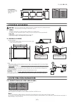
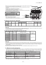
Figure 1
Indoor unit
Indoor unit
Heat source unit
Heat source unit
Heat source unit
Branching pipe set
on the indoor unit side
Model type: DIS
Branching pipe set
on the heat source unit side
Model type: DOS
Branching pipe set
on the indoor unit side
Model type: DIS
Header set on the indoor unit side
Model type: HEAD
A
A
A
E
B
C
C
C
C
D
D
D
D
D
D
D
D
Please note
a) In connecting a heat source unit, please use a pipe conforming to the pipe size specified for heat source unit connection.
b) For pipes connected to the indoor unit (= main pipes), use the pipe size specified above.
c) Always install branching pipes (for both gas and liquid) in such a manner that they form either correct horizontial or vertical branch.
(4) Selection of a heat source unit side branching pipe set
This branching pipe set will always become necessary when units are used in combination.
(When a unit is used as a standalone installation, it is not required)
Heat source unit
For two units (for 450 – 670)
For three units (for 730 – 1000)
Branching pipe set
DOS-2A-3
DOS-3A-3
Please use C1220T-1/2H for
φ
19.05 or larger pipes.
(e) Indoor unit side branching pipe – Indoor unit: Section D in Figure 1
Indoor unit connection pipe size table
Capacity
15, 22, 28
36, 45, 56
71, 90, 112, 140, 160
224
280
Gas pipe
φ
9.52
×
t 0.8
φ
12.7
×
t 0.8
φ
15.88
×
t 1.0
φ
19.05
×
t 1.0
φ
22.22
×
t 1.0
Liquid pipe
φ
6.35
×
t 0.8
φ
9.52
×
t 0.8
Indoor unit
Please use C1220T-1/2H for
φ
19.05 or larger pipes.
(b) Selection of the connection pipe to branching pipes for three heat source units combination:
Section E in Figure 1
Total capacity of heat source units connected
to second branch pipe heat source unit side
Pipe size between branching pipes
450, 500, 560, 615, 670
Gas pipe
φ
28.58
×
t 1.0
Liquid pipe
φ
12.7
×
t 0.8
5-2. Pipe connection position and pipe direction
Total capacity downstream
Less than 180
180 or more but less than 371
371 or more but less than 540
540 or more
Branching pipe set
DIS-22-1G
DIS-180-1G
DIS-371-1G
DIS-540-3
Total capacity downstream
Less than 180
180 or more but less than 371
371 or more but less than 540
540 or more
Header set model type
HEAD4-22-1G
HEAD6-180-1G
HEAD8-371-2
HEAD8-540-3
Number of branches
4 branches at the most
6 branches at the most
8 branches at the most
8 branches at the most
(5) Selection of an indoor unit side branching pipe set
(a) Method of selecting a branching pipe set
●
As an appropriate branching pipe size varies with the connected capacity (total capacity connected
downstream), determine a size from the following table.
Please note
a) In connecting an indoor unit with the indoor unit side branching pipe set, please use a pipe
conforming to the pipe size specified for indoor unit connection.
b) Always install branching pipes (both gas and liquid pipe)
either horizontally or vertically
.
(b) Header Method
●
Depending on the number of units connected, connect plugged pipes (to be procured on the installer’s part) at a branching point (on the indoor unit connection side).
●
For the size of a plugged pipe, please refer to the documentation for a header set (option part).
Please note
a) In connecting a header with an indoor unit, please use a pipe conforming to the pipe size specified for indoor unit connection.
b)
In installing a header, always arrange a gas-side header to branch horizontally and a liquid-side header to branch downward.
c) Indoor units 224 and 280 can not be connected to the header.
Please use C1220T-1/2H for
φ
19.05 or larger pipes.
Pipe sizes applicable to European installations are shown in parentheses.
(d) Indoor unit side first branching pipe – Indoor unit side branching pipe: Section C in Figure 1
Please choose from the table below an appropriate pipe size as determined by the total capacity of indoor units connected downstream, provided,
however, that the
pipe size for this section should not exceed the main size (Section B in Figure 1).
Gas pipe
φ
12.7
×
t 1.0
φ
15.88
×
t 1.0
φ
19.05
×
t 1.0 *
φ
25.4
×
t 1.0
(
φ
28.58)
φ
28.58
×
t 1.0
φ
31.75
×
t 1.1
(
φ
34.92
×
t 1.2
)
φ
38.1
×
t 1.35
(
φ
34.92
×
t 1.2
)
Total capacity of indoor units
Less than 70
70 or more but less than 180
180 or more but less than 371
371 or more but less than 540
540 or more but less than 700
700 or more but less than 1100
1100 or more
Liquid pipe
φ
9.52
×
t 0.8
φ
12.7
×
t 0.8
φ
15.88
×
t 1.0
φ
19.05
×
t 1.0
* When connecting indoor units of 280 at the downstream and the main gas pipe is of
φ
22.22 or larger, use the pipe of
φ
22.22x t1.0.
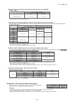
(1) Pipe connecting position and pipe outgoing direction
Please use C1220T-1/2H for
φ
19.05 or larger pipes.
*
Please connect the master and slave units with an oil equalization pipe, when they are used in a combined installation. (It is not required, when a unit is used
as a standalone installation)
When three heat source units combination, please connect using the tee joint (attached to the branching pipe set (DOS-3A-3)).
(a) Heat source unit – Heat source unit side branching pipe: Section A in Figure 1
Please use a pipe conforming to the pipe size specified for heat source unit connection.
Indoor unit connecting pipe size table
(3) Pipe size selection
Capacity
Gas pipe
224
280
335
φ
19.05
× t
1.0
φ
22.22
× t
1.0
φ
25.4 (
φ
22.22)
× t
1.0
Connection method
Flange
Liquid pipe
Heat source unit outlet pipe specifications
Connection method
Connection method
Oil equalization pipe
φ
9.52
× t
0.8
φ
12.7
× t
0.8
Flare
Flare
φ
9.52
× t
0.8
*
Pipe sizes applicable to European installations are shown in parentheses.
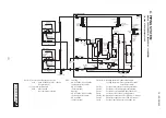
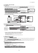
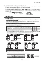
(1) Key consideration for water piping
Please consider following point when designing and installing. (Description of
①
-
⑦
in above figure)
①
Union joint
Be sure to fit it in order to enable the unit replacement easily.
②
Valve
Be sure to fit it for servicing such as cleaning heat exchanger and/or replacing unit and etc.
③
Drain piping
Be sure to make its descending slope as larger as possible and make the distance of its horizontal part as shorter as possible in order to prevent the drain water
from freezing.
④
Strainer
Be sure to fit a strainer (50 mesh or more) at the inlet port of the unit to avoid intrusion of foreign matter into the unit.
⑤
Air purge valve
Be sure to equip it to the place where air may accumulate in order to purge air in the water pipe.
⑥
Water piping
Water piping work shall be done by considering to purge air in the water pipe easily. Insulation work shall be done sufficiently.
⑦
Drain valve
Be sure to equip it in order to drain off the water from the system at servicing.
Select carefully a position where water can be drained completely from piping.
(2) Caution for corrosion
(a)
Water quality
It is important to check in advance whether the feed water and hot water have good quality.
Be sure to use cyclic water and makeup water whose qualities are within the range of water quality standards mentioned in Section 2-1.
(b)
Foreign matter in water
If solid matter such as sand and small stone and/or floating suspended solid such as corrosion product exist in water, the heat-transfer surface of heat exchanger is directly attacked
by water flow, and corrosion may be created locally.
In order to avoid such corrosion by these foreign matters, be sure to fit a cleanable strainer (50 mesh or higher) at the water inlet port of the unit to remove foreign matters.
(3) Others
(a)
Water pipe shall have no water leak and no air intrusion. Especially if air intrudes at suction side of pump, pump performance becomes decreasing and it may cause generation of noise
(b)
Be sure to take into consideration for water pipe not to freeze at stopping operation in winter
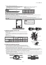
Height difference between
heat source units 0.4m
Height difference between
indoor units 15m
Distance between a heat
source unit and a heat source
unit side branching pipe 5m
Difference in the elevation 50m
Actual length
160m
Equivalent length
185m
Total length
510m
Indoor unit
CAUTION
An installation not conforming to these restrictions can
induce a compressor failure, which shall be excluded from
the scope of warranty. Always observe the restrictions on
the use of pipes in developing a system.
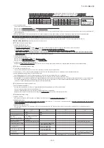
●
Total pipe length
510 m or less
●
Main pipe length
130 m or less
●
Allowable pipe length from the first branching
90 m or less
(However, difference between the longest and shortest piping
40 m or less)
●
Allowable elevation difference (head difference)
(a) When a heat source unit is installed above
50 m or less
(b) When a heat source unit is installed below
40 m or less
(c) Difference in the elevation of indoor units in a system
15 m or less
(d) Elevation difference between the first branching point and the
indoor unit
15 m or less
●
Restrictions on piping applicable to the section between a heat source unit
and a heat source unit side branching pipe (combination unit)
(a) Difference in the elevation
0.4 m or less
(b) Distance between a heat source unit and a heat source unit side branching pipe
5 m or less
(c) Length of oil equalization piping
10 m or less
●
Please use pipes clean on both the inside and outside and free from contaminants harmful to operation such as sulfur, oxides, d ust, chips, oil, fat and water.
●
Use the following material for refrigerant piping.
Material: phosphorus deoxidized seamless copper pipe (C1120T-O, 1/2H, JIS H 3300)
Use C1220T-1/2H for
φ
19.05 or larger, or C1220T-O for
φ
15.88 or smaller
●
Do not use
φ
28.58 x t1.0,
φ
31.8 x t1.1,
φ
34.92 x t1.2 and
φ
38.1 x t1.35 as a bent pipe.
●
Thickness and size: Please select proper pipes according to the pipe size selection guideline.
(Since this unit uses R410A, always use 1/2H pipes of a specified minimum thickness or thicker for all pipes of
φ
19.05 or larger, because the pressure
resistance requirement is not satisfied with O-type pipes).
●
For branching pipes, use a genuine branching pipe set or header set at all times. (optional parts)
●
For the handling of operation valves, please refer to Section 5-5.
●
In installing pipes, observe the restrictions on the use of pipes set out in this Section (1) (Maximum length, total pipe length, allowable pipe length from the first
branching, allowable elevation difference (head difference)) without fail.
●
Install a branching pipe set, paying attention to the direction of attachment, after you have perused through the installation manual supplied with it.
(2) Piping material selection
5. REFRIGERANT PIPING
●
In installing pipes, always observe the restrictions on the use of pipes specified in this Section (1) including Maximum length, Total pipe
length, Allowable pipe length from the first branching, and Allowable elevation difference (head difference)
.
●
Please avoid forming any trap ( ) or bump ( ) in piping as they can cause fluid stagnation.
●
Maximum length (from a heat source unit to the farthest indoor unit)
・・・・・・・・・
160 m or less as actual pipe length (185 m or less as equivalent pipe length)
(When an actual pipe length exceeds 90m, however, it is necessary to change the pipe size. Please determine the main pipe size by consulting with the Main
Selection Reference Table set out in this Section (3) (c).
5-1. Restrictions on the use of pipes
(1) Limitation on use of pipes
Check the connecting positions at water inlet/outlet on the outline drawing in Section 5-2(1).
Water pipe joints in this heat source unit are made of stainless steel. When a pipe made of other kind of metal is connected to the joint, use an insulating material between them to prevent
corrosion resulting from such combination of different metals.
Size of water pipe should be same or larger than the size of water pipe at the product side (R1 1/4).
To avoid from the weight of water pipes being exerted to joints of heat source unit, support the water pipes at places in the building, which are sufficiently strong.
Be sure to tighten joints between water pipes and sockets to a tightening torque not larger than 265 N
・
m.
Devices might be damaged if it is tightened with a torque larger than that.
Install an air vent valve on water pipe where air is likely trapped so that air can be bled effective when filling water in the pipeline.
Be sure to provide anti-freezing means where a risk of freezing is suspected.
When all water pipes have been connected, run the circulating water pump to confirm that there is no water leakage.
Run the circulating water pump to bleed air till water flows out from the air vent on water pipes connected at site.
Run the circulating water pump to flash in water pipes. Clean strainers after the flashing.
Since this product is designed for indoor specifications, perform the piping work with care to avoid water condensation on the control, etc.
4-3. Water pipe connection
Drain pipe joints are provided in front and rear of the heat source unit.
When the joint at the rear is used, remove the plug from the rear joint and attach it to the front joint. Tighten the plug securely.
Size of drain pipe must be same or larger than that of the drain pipe joint (Rp 1/2).
Do not connect the drain pipe to the heat source water outlet.
Incline the drain pipe downward (larger than 1/100), with care to avoid air traps.
After connecting drain pipes, confirm that they are not clogged with dirt and water runs down smoothly.
4-4. Drain pipe
Dress water pipes with heat insulation material to prevent dew condensation.
4-5. Heat insulation
4-2. Outline of water piping
Heat source unit
③
Shows the flow direction of water
Structure of water piping
④
⑦
⑤
①
①
②
②
⑥
⑥
MARK
A
B
C
D
F
G
H
J
K
L
High/low gas line
Suction gas line
*1
Liquid line
Oil equalization line
Water inlet
Water outlet
Drain outlet
Power source intake
Signal wiring intake
Anchor bolt hole
Refer to note.
Refer to note.
Refer to note.
Refer to note.
R1 1/4
R1 1/4
Rp 1/2,2pcs.
φ
35
φ
35
φ
28,4pcs.
Content
Dimension
C1
C2
224,280
142
322
335
139
316
Capacity
(Unit: mm)
High/low gas line
Liquid line
Oil equalization line
φ
19.05
φ
9.52
φ
9.52
φ
22.22
φ
9.52
φ
9.52
φ
25.4
φ
12.7
φ
9.52
*1: In case of heat pump system, not to use Suction gas line.
335
Connection method
Flange
Flare
280
224
Capacity
Note 1. Piping size is as follows.
Please use C1220T-1/2H for
φ
19.05 or larger pipes.
Pipe sizes applicable to European installations are shown in parentheses.
(c) Main (Heat source unit side branching pipe – Indoor unit side first branching pipe): Section B in Figure 1
If the longest distance (measured between the heat source unit and the farthest indoor unit) is 90m or longer (actual length), please change the main pipe size
according to the table below.
Gas pipe
Liquid pipe
Gas pipe
Liquid pipe
φ
19.05
×
t 1.0
φ
22.22
×
t 1.0
φ
25.4 (
φ
22.22)
×
t 1.0
φ28.58
×
t 1.0
φ31.75
×
t 1.1
(φ34.92
×
t 1.2)
φ38.1
×
t 1.35 (
φ34.92
×
t 1.2)
φ
22.22
×
t 1.0
φ
25.4
×
t 1.0
φ31.75
×
t 1.1
(φ28.58
×
t 1.0)
φ38.1
×
t 1.35
(φ34.92
×
t 1.2)
φ
9.52
×
t 0.8
φ
12.7
×
t 0.8
φ
15.88
×
t 1.0
φ
12.7
×
t 0.8
φ
15.88
×
t 1.0
φ
19.05
×
t 1.0
Main pipe size (normal)
Pipe size for an actual length of 90m or longer
Heat source unit
224
280
335
450
500
560
615
670
730
775
850
900
950
1000
(
φ
22.22
×
t 1.0)
Heat source unit
Heat source unit
Summary of Contents for FDC1000KXZWE1
Page 171: ... 14 KX SM 200 169 ...
Page 172: ... 14 KX SM 200 170 ...
Page 173: ... 14 KX SM 200 171 ...
Page 174: ... 14 KX SM 200 172 ...

