'14 • KX-SM-200
–
137
–
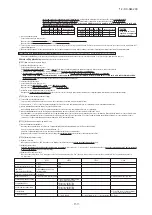
Remote control unit
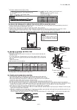
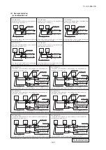
Heat source unit power source 3 phase 4wiring 380-415V
Indoor unit
Heat source unit
Circulating
water pump
Earth leakage breaker
(Impulse withstanding type)
Circuit breaker
for cabling
Circuit breaker
for cabling
Earth leakage breaker
R
R
R
R
R
R
Grounding
wire
A
A
C
D
B
B
E
Distributed, separate power source system
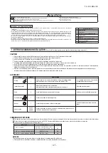
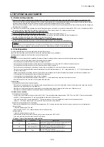
6. ELECTRICAL WIRING WORK
Electrical installation work must be performed by an electrical installation service provider qualified by a power provider of the country.
Electrical installation work must be executed according to the technical standards and other regulations applicable to electrical installations in the country.
Please install an earth leakage breaker without fail
. The installation of an earth leakage breaker is compulsory in order to prevent electric shocks or fire accidents.
(Since this unit employs inverter control, please
use an impulse withstanding type
to prevent an earth leakage breaker’s false actuation.)
Please note
a) Use only copper wires.
Do not use any supply cord lighter than one specified in parentheses for each type below.
- braided cord (code designation 60245 IEC 51), if allowed in the relevant part 2;
- ordinary tough rubber sheathed cord (code designation 60245 IEC 53);
- flat twin tinsel cord (code designation 60227 IEC 41)
- ordinary polyvinyl chloride sheathed cord (code designation 60227 IEC 53).
Please do not use anything lighter than polychloroprene sheathed flexible cord (cord designation 60245 IEC57) for supply cords of parts of appliances for outdoor use.
b)
Use separate power sources for the indoor and heat source units
.
c) A grounding wire must be connected before connecting the power cable. Provide a grounding wire longer than the power cable.
d)
The power sources for indoor units in the same system should turn on and off simultaneously
.
e) Ground the unit. Do not connect the grounding wire to a gas pipe, water pipe, lightning rod or telephone grounding wire.
If improperly grounded, an electric shock or malfunction may result.
Never connect the grounding wire to a gas pipe because if gas leaks, it could cause explosion or ignition.
f)
The installation of an impulse withstanding type earth leakage breaker is necessary
. A failure to install an earth leakage breaker can result in an accident such as an electric
shock or a fire. Do not turn on the power until the electrical work is completed. Be sure to turn off the power when servicing.
g) Please do not use a condensive capacitor for power factor improvement under any circumstances. (It does not improve power factor, while it can cause an abnormal overheat accident)
h) For power source cables, use conduits.
i) Please
do not lay electronic control cables (remote control and signaling wires) and other high current cables together outside the unit
. Laying them together can result in
malfunctioning or a failure of the unit due to electric noises.
j) Power cables and signaling wires must always be connected to the power cable terminal block and secured by cable fastening clamps provided in the unit.
k) Fasten cables so that they may not touch the piping, etc.
l)
When cables are connected, please make sure that all electrical components within the electrical component box are free of loose connector coupling or terminal
connection
and then attach the cover securely. (Improper cover attachment can result in malfunctioning or a failure of the unit, if water penetrates into the box.)
m)Make sure to use circuit breakers (earth leakage breaker and circuit breaker) of proper capacity. Use of breakers of larger capacity could result in trouble on components or fire
accident. The circuit breaker should isolate all poles under over current.
n) Install isolator or disconnect switch on the power supply wiring in accordance with the local codes and regulations. The isolator should be locked in OFF state in accordance with
EN60204-1.
o) After maintenance, all wiring, wiring ties and the like, should be returned to their original state and wiring route, and the necessary clearance from all metal parts should be secured.
CAUTION
If the earth leakage breaker is exclusively for ground fault protection, then you will need to install a circuit breaker for wiring work.
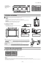
6-1. Wiring system diagrams
A: Power cable (Main power cable) [4 cores]
B: Signal wire (Superlink wire) [2 cores]
C: Power cable (indoor unit power cable)
[2 cores]
D: Remote control cord
[2 cores (FD
○△△
KXE6 indoor unit)]
E: Circulating water pump interlock circuit
Indoor unit power source: Single-phase 220-240V
(Example of combination)
Round crimp contact terminal
Wire
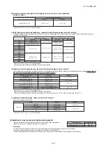
(3) Heat source unit power source specifications
(4) Indoor unit power source specifications : Single phase 220-240V
Please note
a) The method of laying cables has been determined pursuant to the Japanese indoor wiring regulations (JEAC8001). (Please adapt it to the regulations in effect in each country)
b) In the case of distributed, separate power source system, the listed data represent those of a heat source unit.
c) For details, please refer to the installation manual supplied with the indoor unit.
Capacity
Power
source
Cable size for power
source (mm
2
)
Wire length
(m)
Rated current
Switch capacity
Size (mm
2
)
Screw type
Moulded-case circuit breaker (A)
Earth wire
Earth leakage breaker
224
280
335
3 phase
4 wire
380-415V
50Hz
8
67
30
30
2
M5
30A 30mA less than 0.1 sec
●
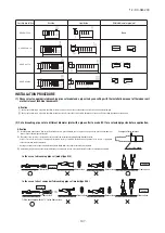
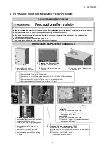
Always connect power cables to the power terminal block and fix power cables to the cramp with using the accessory band as right figure.
●
To connect a cable to the power terminal block, use round solderless terminals.
●
Use specified wires in wiring, and fasten them securely in such a manner that the terminal blocks are not subject to
external force.
●
In fastening a screw of a terminal block, use a correct-size driver.
Fastening a screw of a terminal block with excessive force can break the screw.
●
For the tightening torque of terminals, refer to the following list.
●
When electrical installation work is completed, make sure that all electrical components within the electrical component
box are free of loose connector coupling or terminal connection.
Request
●
When connecting to the power source terminal block,
use the crimp terminals for M5 as shown at right.
●
When connecting to the signal terminal block and the circulating water
pump interlock circuit terminal block
, , use the crimp terminals for M3.5 as shown at right.
Combined total
capacity
of indoor units
Less than 7A
Less than 11A
Less than 12A
Less than 16A
Less than 19A
Less than 22A
Less than 28A
Cable size for
power source
(mm
2
)
Wire length
(m)
2
3.5
5.5
5.5
5.5
8
8
21
21
33
24
20
27
21
2cores x 0.75-2.0 *
Moulded-case circuit breaker
(For ground fault, overload and short circuit protection)
Signal wire size
(mm
2
)
20A 100mA less than 0.1 sec
20A 100mA less than 0.1 sec
20A 100mA less than 0.1 sec
30A 100mA less than 0.1 sec
40A 100mA less than 0.1 sec
40A 100mA less than 0.1 sec
50A 100mA less than 0.1 sec
*
Please use a shielded cable.
Tightening torque (N m)
3 phase 380-415V
0.9-1.2
2.00-2.35
M3.5
M5
Heat source unit signal line terminal block
Water pump interlock curcuit terminal block ,
Power cable terminal block, Earth wire
12.5 mm or less
7 mm or less
Round crimp contact terminal
Circulating water pump ON signal input
Water suspension relay
(Recommended)
(Terminal block 1)
52P-a
TB1
3
4
AC220-240V
Wire
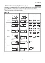
(1) Method of leading out cables
●
As shown on the drawing in Section 5-2 (1), cables can be laid through the front casing.
(2) Notabilia in connecting power cables
Power cables must always be connected to the power cable terminal block and clamped outside the electrical component box.
In connecting to the power cable terminal block, use round solderless terminals.
●
Connect the ground wire before you connect the power cable. When you connect a grounding wire to a terminal block, use
a grounding wire longer than the power cable so that it may not be subject to tension.
●
Do not turn on power until installation work is completed. Turn off power to the unit before you service the unit.
●
Ensure that the unit is properly grounded.
6-2. Method of connecting power cables
Please note
a) The method of laying cables has been determined pursuant to the Japanese indoor wiring regulations (JEAC8001). (Please adapt it to the regulations in effect in each country)
b) Wire length in the table above is the value for when the indoor unit is connect to the power cable in series also the wire size and minimum length when the power drop is less
than 2% are shown. If the current exceeds the value in the table above, change the wire size according to the indoor wiring regulations. (Please adapt it to the regulations in
effect in each country)
c) For details, please refer to the installation manual supplied with the indoor unit.
d) Wires connected to indoor units are allowed up to 5.5 mm
2
. For 8 mm
2
or more, use a dedicated pull box and branch to indoor units with 5.5 mm
2
or less.
6-3. Method of connecting signaling wires
(1)
A standard remote control wire is 0.3mm
2
x 2 cores (FD
○△△
KXE6 indoor unit).
It can be extended
up to 600m. For a remote control wire exceeding 100m,
please upgrade wire size
as specified in the table below
.
Remote control wiring specifications
100 to 200
To 300
To 400
To 600
0.5mm
2
×
2 cores
0.75mm
2
×
2 cores
1.25mm
2
×
2 cores
2
mm
2
×
2 cores
Length (m)
Wire size
FD
○△△
KXE6 indoor unit
The communication protocol can be choosen from following two types. One of them is the conventional Superlink (hereinafter previous SL) and the other is the new Superlink
Ⅱ
(hereinafter new SL) . These two communication protocols have the following advantages and restrictions, so please choose a desirable one meeting your installation conditions
such as connected indoor units and centralized control. When signal cables are connected into a network involving outdoor units, indoor units or centralized control equipment
that do not support new SL, please select communications in the previous SL mode, even if the refrigerant system is separated from theirs.
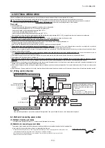
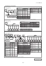
(1) When one heat source unit is used.
(3) The signal lines can also be connected using the method shown below.
○
Indoor and heat source signal lines do not have a polarity.
Any of the connections in the following illustration can be made.
(2) When plural heat source units are used
Signal line
Refrigerant pipe
Network connector
Heat source unit
Heat source unit
Heat source unit
Heat source unit
Indoor unit
Indoor unit
Heat source unit
Heat source unit
Indoor unit
Indoor unit
Indoor unit
Heat source unit
Indoor unit
Indoor unit
Heat source unit
Indoor unit
Indoor unit
Heat source unit
Indoor unit
Heat source unit
Indoor unit
Heat source unit
Indoor unit
Heat source signal
line terminal block
Indoor signal line
terminal block
○
Loop wiring prohibited.
The signal lines cannot form a
loop, so the wirings shown as .......
in the diagram are prohibited.
Important
A
1 B1
A1・B1 A2・B2
A1・B1 A2・B2
A1・B1 A2・B2
A1・B1 A2・B2
A1
B1
A1
B1
A B
A B
A B
B
A
B
A
B
A
B
A
Indoor unit
Indoor unit
B
A
B
A
●
Signal cables are for DC 5 V. Never connect wires for 220/240 V or 380/415 V.
Protective fuse on the PCB will trip.
①
Confirm that signal cables are prevented from applying 220/240 V or 380/415 V.
②
Before turning the power on, check the resistance on the signal cable terminal block. If it is less than 100Ω, power source cables may be connected to the signal cable terminal block.
When units of FD
○△△
KXE6 Series only are connected:
Standard resistance value=5,100/Number of connected units.
When units of FD
○
A
△△
KXE4 and 5 Series only are connected:
Standard resistance value=9,200/Number of connected units.
When units of FD
○△△
KXE6 Series and units of FD
○
A
△△
KXE4 and 5 Series are connected in a mixture:
Standard resistance value=46000/[(Number of connected FD
○
A
△△
KXE4 and 5 Series units x 5) + (Number of connected FD
○△△
KXE6 Series units x 9)]
The number of connected units includes those of indoor units, outdoor units and SL devices..
If the resistance value is less than 100Ω, disconnect the signal cables temporarily to divide to more than one network, to reduce the number of indoor units on the same
network, and check each network.
Outdoor unit setting (SW5-5)
No. of connectable indoor units
No. of connectable outdoor units in a network
Signal cable (total length)
Signal cable (furthest length)
Connectable units to a network
ON
Max. 48
Max. 48
Up to 1000m for 0.75-2mm
2
shielding wire (MVVS)
Up to 1000m
Units not supporting new SL (FD
○
A
△△
KXE4.5
series)
Units supporting new SL (FD
○△△
KXE6
series)
Can be used together.
OFF (Factory default)
Max. 128
Max. 32
Up to 1,500 m for 0.75 mm
2
shielding wire (MVVS)
Up to 1,000 m for 1.25 mm
2
shielding wire (MVVS)
Up to 1000m
Units supporting new SL (FD
○△△
KXE6
series)
Conventional communication protocol (previous SL)
Communication protocol
New communication protocol (new SL)
Note: For FDT224 and 280 models, calculate the number of units taking 1 indoor unit as 2 units for the sake of communication.
Indoor and heat source units signal cables
●
Connect the signal cable between indoor and heat source units and the signal cable between heat source units belonging to the same refrigerant line to A1 and B1.
●
Connect the signal line between heat source units on different refrigerant lines to A2 and B2.
●
Please use a shielded cable for a signal line and connect a shielding earth at all the indoor units and heat source units.
X Y
A B
power cable (220-240V)
L N
A B
Indoor unit
Indoor unit
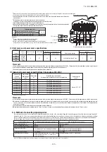
In addition to a possible wiring error between indoor and heat source units, there are other possibilities of erroneous wiring as illustrated below.
It will result in a blown signal line fuse (CNK).
①
Wrong wiring between signaling wires and
remote control wires.
②
Connecting power cables to the signaling wire
terminal block.
(2) When the remote control wire runs parallel to another power source wire or when it is subject to outside noise, such as from a high-frequency device, use
shielded wire. (Be sure to ground only one end of the shielded wire.)
For remote control
Terminal block
For signal wires
Terminal block
For power cables
Terminal block
For signal wires
Terminal block
CAUTION
Remote control wire
Signal wire
Signal wire
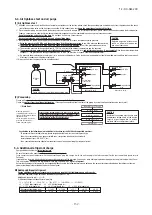
To ensure that the heat source unit operates only when the circulating water pump is running, be sure to connect the pump interlock circuit (auxiliary a-contact of the
electromagnetic switch for the circulating water pump) to terminal block
, (TB1)
of the heat source unit, as shown below.
The auxiliary a-contact must be AC 220 – 240 V, 75 mA or larger.
In case of a combination unit, connect the interlock circuits to all heat source units.
Heat source unit cannot be operated unless an interlock circuit is connected. If operation is stopped owing to this reason, the error code E64-4 will be displayed on the
7-segment indicator on the PCB of heat source unit.
It is recommended also to install a water suspension relay for protection in the event when the water quantity is depleted as a result of faulty operation of valves on the water
pipes, air intrusion, or other.
6-4. Procedure for interlock connection to the circulating water pump
52P-a
●
Address setting methods
The following address setting methods can be used. The procedure for automatic address setting is different from the conventional one.
Please use the automatic address setting function after reading this manual carefully.
This control system controls the controllers of more than one air conditioner's heat source unit, indoor unit and remote control unit through communication control, using the microcomputers built
in the respective controllers. Address setting needs to be done for both heat source and indoor units. Turn on power in the order of the heat source units and then the indoor units.
Use 1 minute as the rule of thumb for an interval between them.
The communication protocol can be chosen from following two types. One of them is the conventional communication protocol (previous SL) and the other is the new communication protocol (new
SL). These two communication protocols have their own features and restrictions as shown by Table 6-3. Select them according the indoor units and the centralized control to be connected.
When signal cables are connected into a network involving heat source units, indoor units or centralized control equipment that do not support new SL, please select communications in the
previous SL mode, even if the refrigerant system is separated from theirs.
When communication is established after setting addresses, check the communication protocol with the 7 segment display panel of the heat source unit.
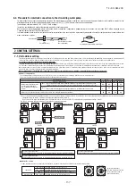
CASE 1
CASE 2
CASE 3
CASE 4
*
1 Do not connect the signal line between heat source units on the different refrigerant lines to A1 and B1. Do not connect the signal line between heat source units on the same
refrigerant line to A2 and B2. This may interrupt proper address setting. (Case 3)
Do not connect the signal line between indoor unit and heat source unit to A2 and B2. This may interrupt proper address setting. (Case 4)
*
2 In Case 2, automatic address setting is not available. Set addresses manually.
Incorrect cable connection
(Cables between heat source units on different refrigerant lines are connected to A1/B1.)
Incorrect cable connection
(Cables between indoor and heat source units are connected to A2/B2.)
Incorrect cable connection
(Cables between heat source units on the same refrigerant line are connected to A2/B2.)
7-1. Unit address setting
Communication protocol
Address setting method
OK
*1
×
*2
OK
OK
OK
OK
OK
OK
OK
×
×
OK
new SL
previous SL
Automatic Manual Automatic Manual
7. CONTROL SETTINGS
Case 1
Case 2
When signal lines linking plural refrigerant systems are provided between heat source units.
(When the network connector is disconnected, refrigerant systems are separated each other)
When signal lines linking plural refrigerant systems are provided between indoor units.
When only one refrigerant system is involved (signal lines do not link plural refrigerant systems)
When plural refrigerant systems
are linked with signal lines
(e.g., to implement centralized
control)
Network connector
Heat source unit
Heat source unit
Heat source unit
Heat source unit
Heat source unit
Heat source unit
Heat source unit
Heat source unit
Heat source unit
Heat source unit
Heat source unit
Heat source unit
Heat source unit
Heat source unit
Heat source unit
Heat source unit
Indoor unit
Indoor unit
Indoor unit
Indoor unit
B
A
B
A
B
A
B
A
Refrigerant pipe
A1・B1 A2・B2
A1・B1 A2・B2
A1・B1 A2・B2
A1・B1 A2・B2
Indoor unit
Indoor unit
Indoor unit
Indoor unit
B
A
B
A
B
A
B
A
A1・B1 A2・B2
A1・B1 A2・B2
A1・B1 A2・B2
A1・B1 A2・B2
Indoor unit
Indoor unit
Indoor unit
Indoor unit
B
A
B
A
B
A
B
A
A1・B1 A2・B2
A1・B1 A2・B2
A1・B1 A2・B2
A1・B1 A2・B2
Indoor unit
Indoor unit
Indoor unit
Indoor unit
B
A
B
A
B
A
B
A
A1・B1 A2・B2
A1・B1 A2・B2
A1・B1 A2・B2
A1・B1 A2・B2
Signal line
0 1
2
3
4
5
6
7
8
9
0 1
2
3
4
5
6
7
8
9
●
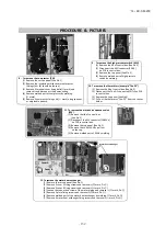
Address No. setting
Set SW1 through 4 and SW5-2 provided on the PCB and SW1 & 2 provided on the heat source unit PCB as shown in the drawings below.
SW1 (SW3)
SW2 (SW4)
For ten’s place
For one’s place
By inserting a flat driver
(precision screw driver) into this
groove and turn the arrow to
point a desired number.
Indoor PCB
Heat source PCB
SW1, 2 (blue)
SW3, 4 (green)
SW5-2
SW1, 2 (green)
For setting indoor No. (The ten’s and one’s)
For setting heat source No. (The ten’s and one’s)
Indoor No. switch (The hundred’s Place) [OFF : 0, ON : 1]
For setting heat source No. (The ten’s and one’s)
Fix the cable using the accessory band
Summary of Contents for FDC1000KXZWE1
Page 171: ... 14 KX SM 200 169 ...
Page 172: ... 14 KX SM 200 170 ...
Page 173: ... 14 KX SM 200 171 ...
Page 174: ... 14 KX SM 200 172 ...

