'14 • KX-SM-200
–
143
–
●
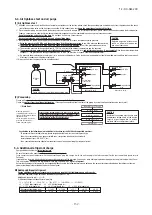
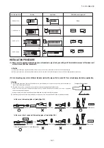
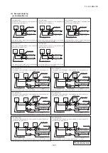
7-segment display indication in automatic address setting
Code
Contents of a display
P30
P31
P32
P34
Code
Contents of a display
The number of the indoor units that can be actually communicated with is less
than the number specified in P33 on the 7-segment display panel.
The number of the indoor units that can be actually communicated with is
more than the number specified in P33 on the 7-segment display panel.
Starting address (P32) + Number of connected indoor units (P33) > 128
While some units are operating in the previous SL mode on the network, the
automatic address setting on multiple refrigerant systems is attempted.
Are signal lines connected properly without any loose connections?
Input the number of connected indoor units again.
Are signal lines connected properly without any loose connections?
Are the network connectors coupled properly?
Input the number of connected indoor units again.
Input the starting address again.
Input the number of connected indoor units again.
Perform manual address setting.
Separate previous SL setting unit from the network
Arrange all units to operate in the new SL.
Code
A01
A02
A03
A04
Contents of a display
Please check
Contents of a display
Cause
Code
E31
E46
Incorrect setting.
Duplicating heat source unit address.
Plural heat source units are exist as same address in same network.
Automatic address setting and manual address setting are mixed.
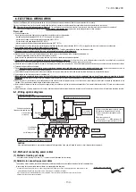
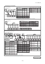
Items that are to be set by the customer
Communication protocol
0: Previous SL mode
1: New SL mode
Polarity difinition
0: Network polarity not defined.
1: Network polarity defined.
AUX
During automatic address setting.
X: The number of indoor units recognized by the heat source unit.
AUE
Indoor unit address setting is completed normally.
End
Polarity is defined. (Automatic address)
Completed normally.
Automatic address start
Input starting address
Specify a starting indoor unit address in automatic address setting.
(The communication plotocol is displayed ; display only)
P33
Input number of connected indoor units
Specify the number of indoor units connected in the refrigerant system in automatic address setting.
7-segment display indication in automatic address setting.
Address setting failure indication
Error indication
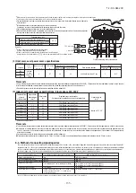
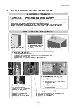
7-2. Control mode switching
Setting value for allocation of external input function
Name
Purpose (at shipping)
Specification
Operating side connector
With external input terminals shorted With external input terminals open
Allowing
Invalid
Heating
Test run start
Cooling
Invalid
External input CnS1
External input CnS2
External input Cn
G
1
External input CnG2
External output CnZ1
External output CnH
External output CnY
External operation input (Shorted at shipping)
Demand input (Shorted at shipping)
Cooling / Heating forced input (Open at shipping)
Silencing mode input (Open at shipping)
Spare output (External output)
Operation output
Error output
Non-voltage contactor (DC12V)
Non-voltage contactor (DC12V)
Non-voltage contactor (DC12V)
Non-voltage contactor (DC12V)
DC12V output
DC12V output
DC12V output
J. S. T (NICHIATSU) B02B-XAMK-1 (LF) (SN)
J. S. T (NICHIATSU) B02B-XARK-1 (LF) (SN)
J. S. T (NICHIATSU) B02B-XAEK-1 (LF) (SN)
J. S. T (NICHIATSU) B02B-XASK-1 (LF) (SN)
MOLEX 5566-02A-RE
MOLEX 5286-02A-BU
MOLEX 5266-02A
Prohibition
Valid
Cooling
Normal
Heating
Valid
"0" : External operation input
"1" : Demand input
"2" : Cooling/heating forced input
"6" : Test run external input 1 (equivalent to SW5-1)
"7" : Test run external input 2 (equivalent to SW5-2)
"9" : 2 stage demand input
Controls of heat source unit may be selected as follows using the dip switches on the PCB and P
○○
on the 7-segment.
To change P
○○
on the 7-segment, hold down SW8 (increasing a number shown on the 7-segment display panel: one’s place), SW9 (increasing a number shown on the
7-segment display panel: tens place) and SW7 (Data write/Enter).
By changing the allocation of external input functions (P07-10) on the 7-segment, functions of external
input terminals may be selected. Inputting signals to external input terminals enable the following functions.
Control selecting method
Content of control
7-3. External input and output terminals specifications
SW setting on PCB
SW5-5
P
○○
on 7-segment
SW3-7 to ON *
1
SW5-1 to ON + SW5-2 to OFF
Heating test run
SW5-1 to ON + SW5-2 to ON
Cooling test run
Communication method selection ON: Previous SL communication, OFF: New SL communication
Operation priority select
0: First push preferred (at shipping)
1: Last push preferred
J13: Shorted (at shipping), J13: Open
External input switing (CnS1, CnS2 only) shorted : Level input, Open: Pulse input
2 stage demand mode *
2
Silent mode setting 0 (at shipping) – 3 : Larger values for large effect
Allocation of external output (CnZ1)
Allocation of external input (CnS1)
Allocation of external input (CnS2)
Allocation of external input (CnG1)
Allocation of external input (CnG2)
Pump down operation
SW4-5:OFF, SW4-6:OFF*
1
80% (at shipping)
SW4-5:ON , SW4-6:OFF*
1
60%
SW4-5:OFF, SW4-6:ON*
1
40%
SW4-5:ON , SW4-6:ON*
1
00%
ー
ー
ー
ー
ー
Close the fluid operation valve on heat source unit and set as follows:
(1) SW5-2 on PCB to ON
(2) SW5-3 on PCB to ON
(3) SW5-1 on PCB to ON
Forced cooling/heating operation mode
(It can be fixed at cooling with external input terminals open, or at heating with them closed.)
Set external input function
allocation to “2” *
1
Set allocation of external
input function to “1” *
1
Inputting signals to external input terminals selects the demand mode.
(J13 shorted: Level input, J13 open: Pulse input)
OFF: Disabled (at shipping)
000, 040, 060, 080 [%]
P04
P05
P06
P07
P08
P09
P10
P01
Control is switched when both the allocation of external input function (P07-10) and SW are changed.
(Example: To use CnS1 for the input of forced cooling/heating operation mode, set P07 at 2 and SW3-7 at ON. To use CnS2 for the input of forced cooling/heating operation
mode, set P08 at 2 and SW3-7 at ON.)
To enable the 2 stage demand mode, set J13 shorted and allocation of external input function to “1”.
*
1
*
2
ー
ー
ー
ー
ー
ー
ー
ー
"0" : Operation output
"1" : Error output
"2" : Compressor ON output
By changing the allocation of external output function
(P06) on the 7-segment, functions of external output
terminal (CnZ1) may be selected.
(1)
Make sure that a measurement between the power source terminal block and ground, when measured with a 500V megger, is greater than 1 M
Ω
.
When the unit is left for a long time with power OFF or just after the installation, there is possibility that the refrigerant is accumulated in the compressor and the
insulation resistance between the contact terminals for power source and grounding decreases to 1M
Ω
or around.
When the insulation resistance is 1M
Ω
or less, the insulation resistance will rise with crank case heater power ON for 6 hours or more because the refrigerant in
the compressor is evaporated.
(2) Please check the resistance of the signaling wire terminal block before power is turned on. If a resistance measurement is 100
Ω
or less, it suggests a possibility
that power cables are connected to the signaling wire terminal block. (Please refer to Section 6-3. Standard resistance value.)
(3)
Be sure to turn on the crank case heater 6 hours before operation
.
(4)
Make sure that the bottom of the compressor casing is warm
. (higher than ambient tempe5°C)
(5) Be sure to fully open the operation valves (liquid,gas and Equalizen oil piping (for a combined installation only)) for the outdoor unit.
Operating the outdoor unit with the valves closed may damage the compressor.
(6)
Check that the power to all indoor units has been turned on. If not, water leakage may occur
.
(7) Run the circulating water pump, and confirm that the water temperature and flow rate are within the limitation for use.
It is recommended to practice the check operation in precedent to the test run.
[Even if the check operation is not practiced, the test run and normal operations can be performed.]
For further details regarding the check operation refer to the technical data.
・
Practice the check operation after completing the address setting for the indoor and heat source units and also after charging the refrigerant.
・
To assure accurate checking, proper amount of refrigerant must be retained.
・
Check operation cannot be done when the system is stopped by an error.
・
Check operation cannot be done when the total capacity of connected indoor units is less than 80% of the heat source unit capacity.
・
Check operation cannot be done when the system communication method is previous SL.
・
Don’t perform the check operation simultaneously on more than one refrigerant line. Accurate checking cannot be obtained.
・
Practice the check operation within the operation temperature ranges (Ambient temperature: 0 – 40°C, room temperature: 10 – 32°C). Check operation will not
start out of these ranges.
・
Outdoor air processing unit cannot be checked. (It is possible to check indoor units other than the outdoor air processing unit of the same refrigerant line.)
・
It is impossible to check operation when connecting only one indoor unit.
・
It is impossible to check operation when demand rate is setting 0%.
・
If the compressor under dome superheat degree is lower than 15°C, check operation may not work with a protective control.
・
Be sure to turn on the crank case heater 6 hours before check operation.
Check operation allows proving the following points.
・
Whether or not the operation valve is left open (Operation valve open/close check). (In case of combination, however, all operation valves need to be closed on
master and slave units to obtain accurate judgment.)
・
Whether or not the refrigerant pipes and signal cables are connected properly between indoor and heat source units. (Mismatch check)
・
Whether or not the indoor expansion valve operates properly. (Expansion valve failure check)
CAUTION
Please make sure that the operation valves (gas, liquid, oil equalization pipe (for a combined installation only)) are full
open before a test run. Conducing a test run with any of them in a closed position can result in a compressor failure.
8. TEST OPERATION AND TRANSFER
8-1. Before starting operation
8-2. Check operation
Important
(1)
Check items
Display on 7-segment indicator during check operation
(a) Starting the check operation
・
Confirm that all of the following switches are turned OFF: SW3-7 (Forced cooling/heating operation mode), SW5-1 (Test run), SW5-2 (Test run cooling setting)
and SW5-3 (Pump-down operation). (In case of combination, on both master and slave units)
・
At the next, turn the SW3-5 (Check operation) OFF ON (only on master unit in case of combination) so that the check operation will start.
・
It takes 15 – 30 minutes normally (max. 80 min) from the start to the end of check operation.
(b) End the check operation and the result display
・
When the check operation is over, the system stops automatically. The 7-segment indicator shows the result (only on master unit in case of combination).
<Normal ending>
・
7-segment indicator shows “CHO End”.
・
Return the SW3-5 to OFF. The 7-segment indicator returns to normal display.
<Abnormal ending>
・
7-segment indicator shows an error alarm.
・
Referring to the section [Inspect here], repair the faulty section and return the SW3-5 to OFF.
・
At the next, repeat the check operation from the Step (2) above.
(2)
Method of check operation
Code indicato
r
Data indicator
Display contents
Max. remaining time
Max. remaining time
H1
H2
CHO
End
Check operation preparation on. Indicates max. remaining time (min).
(In case of combination, indicated on master unit only.)
Check operation on. Indicates max. remaining time (min).
(In case of combination, indicated on master unit only.)
Normal ending of check operation.
(In case of combination, indicated on master unit only.)
Error display on 7-segment indicator after ending the check operation
Code indicator
Data indicator
Display contents
Check following points
CHL
CHU
CHJ
CHE
Operation valve is closed.
(Refrigerant circuit is shut off
partially.)
・
Isn’t the operation valve of heat source unit left open?
・
Is the low pressure sensor normal? (Detected pressure can be seen on
the 7-segment indicator.)
・
Is the connector of indoor unit expansion valve coil connected?
・
Isn’t the indoor unit expansion valve coil disconnected from the
expansion valve body?
・
Is the indoor unit heat exchanger sensor normal? (Check if the sensor is
disconnected.)
Mismatch between
refrigerant pipes and signal
cables. Refrigerant is not
circulated to the indoor unit of
which No. is displayed.
・
Are the refrigerant pipes and signal cables connected properly between
the indoor and heat source units?
・
Is the connector of indoor unit expansion valve coil connected?
・
Isn’t the indoor unit expansion valve coil disconnected from the
expansion valve body?
・
Is the indoor unit heat exchanger sensor normal? (Check if the sensor is
disconnected.)
Expansion valve on the indoor
unit of which No. is displayed
is not operating properly.
・
Is the connector of indoor unit expansion valve coil connected?
・
Isn’t the indoor unit expansion valve coil disconnected from the
expansion valve body?
・
Is the indoor unit heat exchanger sensor normal? (Check if the sensor is
disconnected.)
Abnormal ending of check
operation.
・
Isn’t any error displayed (E??) on the indoor unit or heat source unit?
・
Are signal cables connected without play?
・
Hasn’t the SW setting been changed during the check operation?
※
When any error is detected, errors other than those listed above may be displayed. In such occasion, refer to the separate technical data.
Abnormal indoor unit No.
Abnormal indoor unit No.
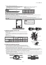
(1) To avoid mixing of different types of oil, use separate tools for each type of refrigerant.
(2) To avoid moisture from being absorbed by the refrigerant oil, the time for when the refrigerant circuit is open should be kept as short as possible. (Within 10 min. is
ideal.)
(3) For other piping work, airtighteness testing , vacuuming, and refrigerant charging, refer to section 5, Refrigerant piping.
(4) Diagnostic Inspection Procedures
For the meanings of failure diagnosis messages, please refer to the nameplate provided on the unit (on the control lid)
(5) 7-segment LED indication
Data are indicated when so chosen with the indication selector switch. For the details of indication, please refer to the cable name plate attached on the unit. (On the
control lid)
(6) Internal wiring
After maintenance, all wiring, wiring ties and the like, should be returned to their original state and wiring route, and the necessary clearance from all metal parts
should be secured.
(7) When it becomes necessary to recover the refrigerant for maintenance or in the event of the pump-down operation for removal or relocation of the heat source unit,
drain water completely from the water heat exchanger or continue to circulate heat source water.
There is a risk of puncture on the water heat exchanger, if water freezes.
(8) Confirm at periodic inspections that the temperature, flow rate and quality of heat source water are within the limitation for use.
(2) Method of starting a test run for a cooling operation from a heat source unit: please operate a remote control unit according to the following steps.
(a) Start of a cooling test run
○
Operate the unit by pressing the START/STOP button.
○
Select the “COOLING” mode with the MODE button.
○
Press the TEST RUN button for 3 seconds or longer.
The screen display will be switched from “Select with ITEM ”
→
“Determine with SET ”
→
“Cooling test run
▼
.”
○
When the SET button is pressed while “Cooling test run
▼
” is displayed, a cooling test run will start. The screen display will be switched to “COOLING TEST RUN.”
(b) Termination of a cooling test run
○
When the START/STOP button or the “TEMP SET ” button is pressed, a cooling test run will be terminated.
Notes : for engineers undertaking piping or electrical installation work
When a test run is completed, please make sure again that the electrical component box cover and the main body panel have been attached before you turn
the unit over to the customer.
9. CAUTIONS FOR SERVICING (for R410A and compatible machines)
(1) Test run from a heat source unit.
Whether external inputs are set to ON or OFF, you can start a test run by using the SW5-1 and SW5-2 switches provided on the heat source unit board.
Select the test run mode first.
Please set SW5-2 to ON for a cooling test run or OFF for a heating test run. (It is set to OFF at the factory for shipment)
Turning SW5-1 from OFF to ON next will cause all connected indoor units to start.
When a test run is completed, please set SW5-1 to OFF.
Note: During a test run, an indoor unit cannot be operated from the remote control unit (to change settings). (“Under centralized control” is indicated)
8-3. Test operation
8-4. TRANSFER
○
Use the instruction manual that came with the heat source unit to explain the operation method to the customer.
Please ask the customer to keep this installation manual together with the operation manual of his indoor units.
○
Instruct the customer that the power should not be turned off even if the unit is not to be used for a long time. This will enable operation of the air conditioner any time.
(Since the compressor bottom is warmed by the crank case heater, seasonal compressor trouble can be prevented.)
▲
▼
Summary of Contents for FDC1000KXZWE1
Page 171: ... 14 KX SM 200 169 ...
Page 172: ... 14 KX SM 200 170 ...
Page 173: ... 14 KX SM 200 171 ...
Page 174: ... 14 KX SM 200 172 ...


