'14 • KX-SM-200
–
150
–
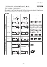
(b) Heat source unit connection
If the longest distance is
less than 90m
(
actual length
)
Heat source unit
335
A
22
28
56
140
140
B
D
b
a
C
c
e
d
Indoor unit
Branching
pipe 1
Item
A
B
C
D
a
b
c
d
e
If the longest distance is
90m or longer
(
actual length
)
Downstream indoor unit
capacity total
(
56+140+140
)=
336
(
140+140
)=
280
Indoor unit piping size
(
22
)
Indoor unit piping size
(
28
)
Indoor unit piping size
(
56
)
Indoor unit piping size
(
140
)
Indoor unit piping size
(
140
)
Selection procedure
φ
25.4
φ
25.4
φ
12.7
φ
12.7
Piping size
Gas pipe Liquid pipe
φ
19.05
φ
19.05
φ
12.7
φ
6.35
φ
9.52
φ
15.88
φ
9.52
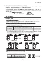
Example 1
:
Branch system
Connecting capacity
:
386
Selecting piping size
(
56
+
140
+
140
)=
336
Branching
pipe 1
(
140
+
140
)=
280
(
22
+
28
+
56
+
140
+
140
)=
386
Selection of branching pipe set.
(
Than table 7 of PCB003Z847
)
Item
Selection procedure
DIS-371-1G
DIS-180-1G
Branching pipe set
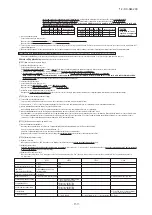
Example 2
:
Header system
Connecting capacity
:
285
Indoor unit
A
280
112
71
36
22
a
22
22
b
c
d
e
f
Header 1
φ
9.52
φ
9.52
φ
12.7
φ
15.88
φ
15.88
φ
25.4
(
φ
22.22
)
φ
22.22
Indoor unit piping size
(
22
)
Indoor unit piping size
(
22
)
e
d
Indoor unit piping size
(
36
)
Indoor unit piping size
(
71
)
Indoor unit piping size
(
112
)
If the longest distance is 90m or longer
(
actual length
)
If the longest distance is less than 90m
(
actual length
)
b
c
a
A
Selecting piping size
Item
Selection procedure
φ
9.52
φ
9.52
φ
12.7
φ
9.52
Piping size
Gas pipe
Liquid pipe
Indoor unit piping size
(
22
)
f
φ
6.35
φ
9.52
HEAD6-180-1G
Header set
Header 1 Downstream indoor unit capacity total
(
112+71+36+22+22+22
)=
285
Selection header set.
(
Than table 8 of PCB003Z847
)
Item
Selection procedure
(
22+28
)=
50
Table 1 and
table 3
Table 4
Table 4
Table 4
Table 5
Table 5
Table 5
Table 5
Table 5
Table 1 and
table 3
Table 5
φ
15.88
DIS-180-1G
φ
12.7
φ
9.52
φ
9.52
φ
6.35
φ
6.35
φ
9.52
φ
12.7
φ
12.7
φ
6.35
φ
6.35
φ
6.35
(
22
+
28
)=
50
DIS-22-1G
Branching
pipe 2
Branching
pipe 3
Branching
pipe 4
Selection table
of PCB003Z847
Table 5
Table 5
Table 5
Table 5
Table 5
Selection table
of PCB003Z847
Heat source unit
Downstream indoor unit capacity total
Downstream indoor unit capacity total
Downstream indoor unit
capacity total
Downstream indoor unit
capacity total
Downstream indoor unit capacity total
Downstream indoor unit capacity total
Branching
pipe 2
Branching
pipe 3
Branching
pipe 4
(
φ
22.22
)
(
φ
22.22
)
Refrigerant piping size applicable to European installations are shown in parentheses.
Refrigerant piping size applicable to European installations are shown in parentheses.
22
140
71
90
45
E
a
F
Indoor unit
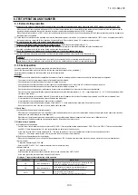
Example 3
:
Branch system
+
Header system
Connecting capacity
:
1115
D
G
H
b
c
d
e
Header 1
224
f
g
36
71
h
56
i
j
160
k
45
28
l
m
56
n
71
Piping size
Selection procedure
Item
φ
22.22
H
(
140+71+90+45
)
=346
Downstream indoor unit
capacity total
+28+56+71
)
=523
(
36+71+56+160+45
Downstream indoor unit
capacity total
+45+28+56+71
)
=747
(
224+36+71+56+160
Downstream indoor unit
capacity total
+28+56+71
)
=1093
+36+71+56+160+45
(
140+71+90+45+224
Downstream indoor unit
capacity total
Heat source unit piping size
(
335
)
G
F
If the longest distance is
90m or longer
(
actual length
)
If the longest distance is
less than 90m
(
actual length
)
E
B
D
A
φ
25.4
φ
31.75
φ
38.1
Gas pipe
φ
38.1
φ
31.75
φ
25.4
Selecting piping size
Selection procedure
Item
Indoor unit piping size
(
56
)
Indoor unit piping size
(
28
)
Indoor unit piping size
(
45
)
Indoor unit piping size
(
160
)
Indoor unit piping size
(
56
)
Indoor unit piping size
(
71
)
Indoor unit piping size
(
36
)
Indoor unit piping size
(
224
)
Indoor unit piping size
(
45
)
Indoor unit piping size
(
90
)
Indoor unit piping size
(
71
)
Indoor unit piping size
(
140
)
Indoor unit piping size
(
22
)
φ
12.7
φ
15.88
φ
12.7
φ
19.05
φ
15.88
φ
19.05
φ
12.7
Liquid pipe
l
m
n
k
j
g
h
i
e
f
b
c
d
a
Gas pipe
φ
12.7
φ
12.7
φ
15.88
φ
9.52
Liquid pipe
φ
6.35
(
36+71+56+160+45+28
(
140+71+90+45
)=
346
+45+28+56+71
)=
747
(
224+36+71+56+160
+45+28+56+71
)=
1093
+36+71+56+160+45
(
140+71+90+45+224
(
22+140+71+90+45+224
+56+71
)=
523
Header 2
Downstream indoor unit capacity total
Selection header set.
(
Than table 8 of PCB003Z847
)
Downstream indoor unit capacity total
Downstream indoor unit capacity total
+36+71+56+160
+28+56+71
)=
1115
Downstream indoor unit capacity total
Downstream indoor unit capacity total
Header 1
Item
Branching
pipe 3
Branching
pipe 1
Selection procedure
HEAD8-371-1G
HEAD8-180-1G
Header set
DIS-540-3
Piping size
Selection of branching pipe set.
(
Than table 7 of PCB003Z847
)
Item
Selection procedure
Branching pipe set
Table 1
Table 1
Table 3
Table 4
Table 4
Table 4
Table 4
Table 5
Header 2
DIS-540-3
DIS-540-3
φ
6.35
φ
6.35
φ
6.35
φ
6.35
φ
6.35
φ
9.52
φ
9.52
φ
6.35
φ
9.52
φ
9.52
φ
9.52
φ
9.52
φ
9.52
φ
15.88
φ
15.88
φ
19.05
φ
15.88
φ
15.88
φ
12.7
φ
12.7
φ
12.7
335
B
280
C
Heat source
unit 1
335
A
The 2nd
branching
[
DOS
−
3A
−
3
]
I
C
φ
22.22
φ
9.52
Table 1
φ
28.58
I
Heat source unit capacity
total connect to the 2nd
branching
φ
12.7
Table 2
The 1st
branching
[
DOS
−
3A
−
3
]
φ
25.4
φ
12.7
(
335+335
)
=670
Indoor unit piping size
(
71
)
φ
9.52
φ
15.88
Branching
pipe 1
Branching
pipe 2
Branching
pipe 3
Table 5
Table 5
Table 5
Table 5
Table 5
Table 5
Table 5
Table 5
Table 5
Table 5
Table 5
Table 5
Table 5
Selection table
of PCB003Z847
Selection table
of PCB003Z847
Heat source
unit 2
Heat source
unit 3
Heat source unit piping size
(
335
)
Heat source unit piping size
(
280
)
Branching
pipe 2
Oil equalization pipe
Selection procedure
Item
Piping size
Selection table
of PCB003Z847
Oil equalization pipe
J
φ
9.52
Table 1
J
Refrigerant piping size applicable to European installations are shown in parentheses.
(
φ
22.22
)
(
φ
22.22
)
(
φ
34.92
)
(
φ
34.92
)
(
φ
34.92
)
(
φ
28.58
)
PCB003Z848
Summary of Contents for FDC1000KXZWE1
Page 171: ... 14 KX SM 200 169 ...
Page 172: ... 14 KX SM 200 170 ...
Page 173: ... 14 KX SM 200 171 ...
Page 174: ... 14 KX SM 200 172 ...


