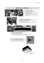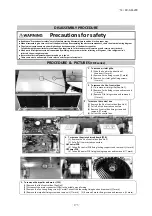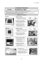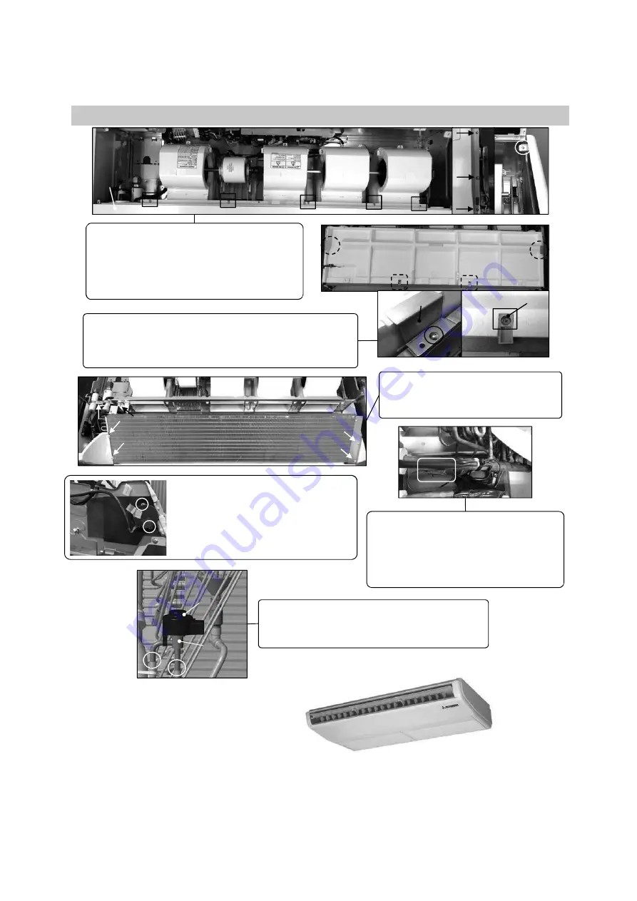
6. To remove side panel and bottom panel
(1) Remove air inlet grille.(See No.1)
(2) Remove the right and left side panel fixing
screws and remove it.(
mark)
(3) Remove 5 bottom panel fixing screws.(
mark)
Remove 6 bottom panel fixing screws and
remove it. (
mark, left and right side)
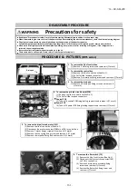
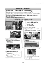
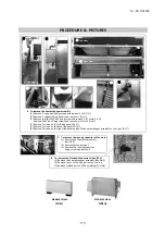
7. To remove drain pan
(1) Remove side panel and bottom panel.(See No.5)
(2) Remove 2 plate fixing screws and remove it.(
mark, Pic.
)
(3) Remove 2 support fixing screws and remove it.(
mark, Pic.
)
(4) Pull out the drain pan.
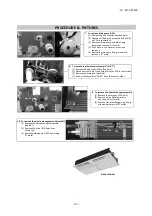
8. To remove the heat exchanger assembly
(1) Remove the drain pan.(See No.6)
(2) Remove 6 heat exchanger assy fixing
screws and remove it.(
mark)
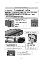
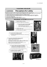
9. To remove the louver motor (LM)
(1) Remove the lid of control box.(See No.1)
(2) Disconnect the louver motor connector
(CNJ) on PCB in control box.
10. To remove the thermistors (example"Thi-R3")
(3) Remove side panel.(See No.5)
(1) Remove the lid of control box.(See No.1)
(4) Remove 2 louver motor fixing screws
(2) Disconnect the Tho-R3 connector(CNNx)
and remove it.
on PCB in control box.
(3) Remove the drain pan.(See No.3)
(4) Pull out the thermistor"Thi-R1" from
the sensor holder.
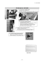
11. To remove the Electronic Expansion Valve (EEV)
(1) Remove the heat exchanger assembly.(See No.9)
(2) Remove the coil of EEV by pull out on the top.
(3) Remove welded part of EEV by welding.(
mark)
PROCEDURE & PICTURES
Bottom panel
Plate
Support
EEV
Coil of EEV
General view
'14 • KX-SM-200
–
1
7
4
–
Summary of Contents for FDC1000KXZWE1
Page 171: ... 14 KX SM 200 169 ...
Page 172: ... 14 KX SM 200 170 ...
Page 173: ... 14 KX SM 200 171 ...
Page 174: ... 14 KX SM 200 172 ...

