–
127
–
'14 • KX-SM-204
2.5 Outdoor unit inverter PCB replacement procedure
Precautions for Safety
¡
Since the following precaution is the important contents for safety, be sure to observe them.
WARNING and CAUTION are described as follows:
Indicates an imminently hazardous situation which will result in death or serious injury if
proper safety procedures and instructions are not adhered to.
Indicates a potentially hazardous situation which may result in minor or moderate injury
if proper safety procedures and instructions are not adhered to.
WARNING
¡
Securely replace PCB according to this procedure.
If the PCB is incorrectly replace, it will cause an electric shock or fi re.
¡
Be sure to check that the power source for the outdoor unit is turned OFF before replacing the substrate.
The PCB replace under current-carrying will cause an electric shock of fi re.
¡
After fi nishing the PCB replacement, check that wiring is correctly connected with the PCB before power distribu-
tion. If the PCB is incorrectly replaced, it will cause an electric shock or fi re.
CAUTION
¡
Bundle the wiring so as not to tense because it will cause an electric shock.
WARNING
CAUTION
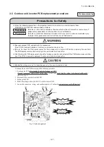
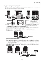
CNI2
CNR
JSW10,11
CNI3
CNA
After elapsing 3 minutes
from power OFF
Connectors are not
half inserted
Fig.1 Parts arrangement
Exchange the inverter PCB according to the following procedure.
1. Exchange the PCB
after elapsing 3 minutes from power OFF
.
(
Be sure to measure voltage (DC) of two place
((A),(B)) and
check that the voltage is discharged sufficiently. )
2. Disconnect the connectors from the PCB.
3. Exchange the PCB.
4. Match the setting switches (JSW10,11) with the former PCB.
5. Connect the connectors , wiring , and snubber capacitor .(Confirm the
connectors are not half inserted
.)
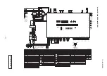
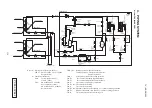
(Refer to Fig 3)
PCB012D057B


