–
128
–
'14 • KX-SM-204
(
A
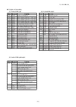
) Control PCB voltage measurement points
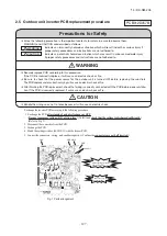
Target PCB(INV2)
Target PCB(INV1)
Fig.2 Voltage measurement points
(F1-DS(-))
(
B
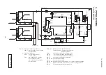
) Inverter PCB
(
INV1,2
)
voltage measurement points
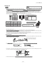
Procedure on tightening harness (snubber capacitor) and power transistor with screw.A metallic connection binder is set in
each hole of the inverter PCB of "P", "N", "U", "V", and "W" beforehand. Then tighten the harness (snubber capacitor) and
the power transistor with the screw together.
Fig.3 Installation method to power transistor
Terminal
Harness
Snubber capacitor
Inverter PCB
Power transistor
Connection binder
(
Metallic pillar
)
(DM (+) - DM(-))
(Set the harness wires to be fixed to "U"and "W" with screws in respective holes after passing them through IC21 and 22.)
(
Connect snubber capacitor with "P" and "N".
)


