background image

-

 138 

-

 '14 • KX-SM-204

720

764

726

594

85

85

850

1350

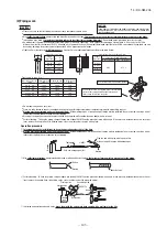
Anchor bolt positions
 (

 mark)

Unit

20

Over

100

mm

Normally, it is desirable that a 

base as specified in the drawing 

above is provided.

A base used for a former model 

is wrongly oriented and not 

acceptable.

Please use it for renewal installation.

(Please add a base on the center)

It is necessary to prevent sagging.

Base

Unit leg

Vibration

isolating rubber

85

Outdoor unit

Outdoor unit

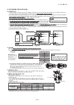
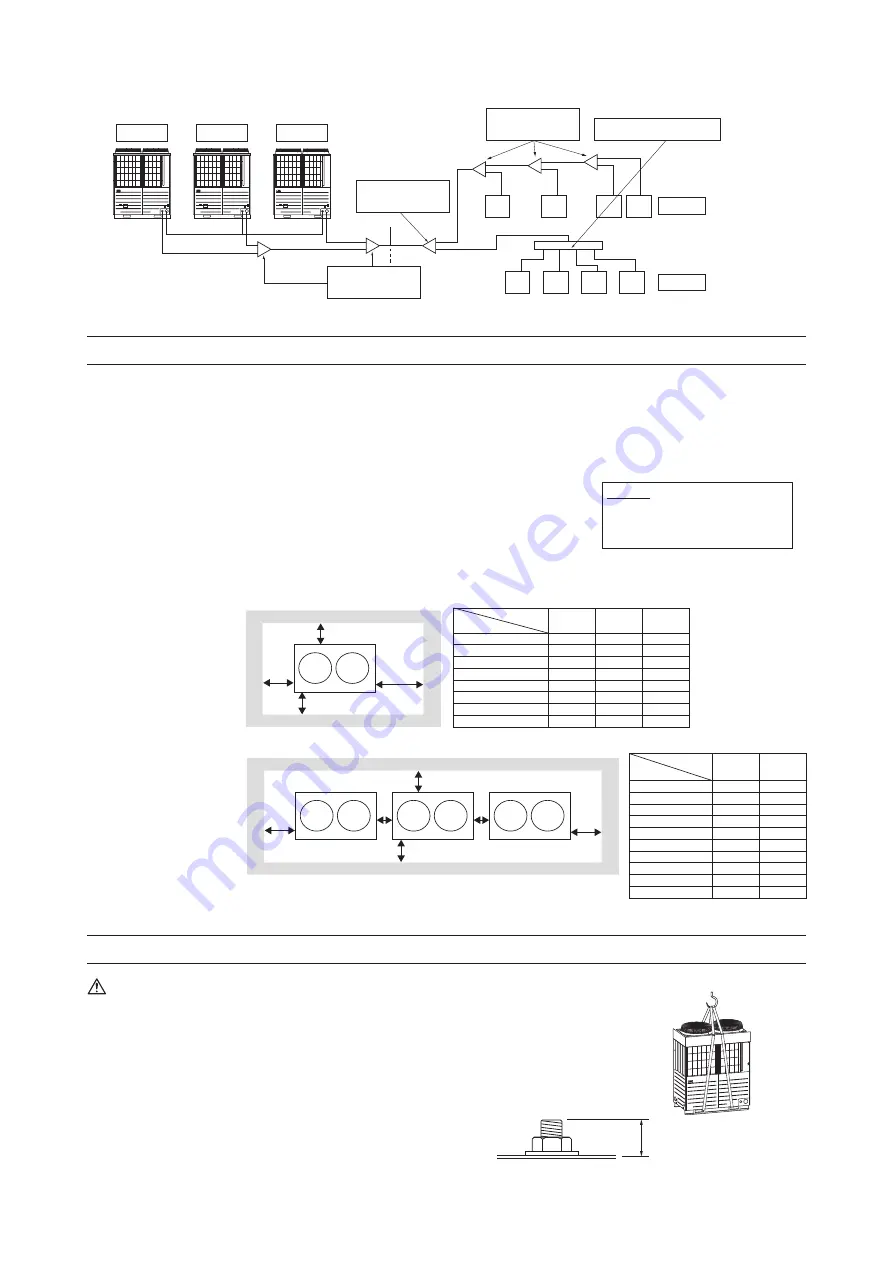
Height difference between 

outdoor units 0.4m

Height difference between 

indoor units 18m

Distance between an outdoor 

unit and an outdoor unit side 

branching pipe 5m

Difference in the elevation    50m

(Max 70m)

Actual length 

160m

Equivalent length 

185m

Total length 

1000m

Indoor unit

Figure 1

Indoor unit

Indoor unit

Outdoor unit

Outdoor unit

Outdoor unit

Branching pipe set

on the indoor unit side

Model type: DIS

Branching pipe set

on the outdoor unit side

Model type: DOS

Branching pipe set

on the indoor unit side

Model type: DIS

Header set on the indoor unit side

Model type: HEAD

E

A

A

B

C

C

C

C

D

D

D

D

D

D

D

D

A

A

CAUTION

An installation not conforming to these restrictions 

can  induce  a  compressor  failure,  which  shall  be 

excluded  from  the  scope  of  warranty.  Always 

observe  the  restrictions  on  the  use  of  pipes  in 

developing a system.

CAUTION

Please  leave  sufficient  clearance  around 

the  unit  without  fail.  Otherwise,  a  risk  of 

compressor  and/or  electric  component 

failure may arise.

MITSUBISHI HEAVY INDUSTRIES, LTD.   

MULTI AIR CONDITIONER OUTDOOR UNIT FOR BUILDINGS

KXZ Hi-COP SERIES INSTALLATION MANUAL

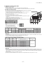
Notabilia as a unit designed for R410A

a)
b)
c)
d)
e)

f)

g)
h)

Gauge manifold
Charge hose
Electronic scale for refrigerant charging
Torque wrench
Flare tool
Protrusion control copper pipe gauge
Vacuum pump adapter
Gas leak detector

Dedicated R410A tools

CAUTION

ACCESSORY

  ●

Please read this manual without fail before you set to installation work and carry it out according to this manual.

  ●

For the installation of an indoor unit, please refer to the installation manual of an indoor unit.

  ●

For piping work, option distribution parts (branching pipe set, header set) are necessary.  Please refer to our catalog, etc.

  ●

Never fail to install an earth leakage breaker. (Please use one tolerable to harmonic components)

  ●

Operating the unit with the outlet pipe thermistor, the inlet pipe thermistor, the pressure sensor, etc. removed can result in a compressor burnout.  Avoid operation 

under such conditions in any circumstances.

  ●

With this air-conditioning system, room temperature may rise, depending on installation conditions, while indoor units are stopped, because small quantity of 

refrigerant flows into the stopped indoor units if heating operation is conducted on the system. 

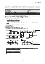
COMBINATION PATTERNS

The same outdoor unit is used whether it is used alone or in combination with another unit.

  ●

Please note that an installation involving a combination other than those listed below is not operable. (For example, you cannot operate 280 and 400 in combination)

● 

The possible outdoor unit combinations and the number and the total capacity of indoor units that can be connected in a system are shown in the table below.

● 

Please always use indoor units designed exclusively for R410A. For connectable indoor unit model names, please check with our catalog, etc.

● 

It can be used in combination with the following indoor unit.

Option parts

Refrigerant distribution piping components supplied as optional parts will become necessary in installing the unit.

As refrigerant distribution piping components, branching pipe sets (model type: DOS) for the outdoor unit side piping, branching pipe sets (model type: DIS) and 

header sets (model type: HEAD) for the outdoor unit side piping are available.

Select according to the application. Please refer to "4. Refrigerant piping work" in selecting.

If you are uncertain, please do not hesitate to consult with your distributor or the manufacturer.

Please use refrigerant branching sets and header sets designed exclusively for R410A without fail.

Name

Wiring

Quantity

2

1

Usage location

In operating the unit in the silent mode or the forced cooling/heating mode, 

insert it to the outdoor unit board

'

s CNG.

It is supplied with the unit.  You can find 

it taped inside the control box.

Instruction manual

When the installation work is completed,

give instructions to the customer and ask him/her to keep it.

Attached on the side panel below the 

operation valve.

Capacity

224

280

335

450

500

560

615

670

735

800

850

900

950

1000

Combination patterns

Single
Single
Single

Combination

224+224

)

Combination

224+280

)

Combination

280+280

)

Combination

280+335

)

Combination

335+335

)

Combination

224+224+280

)

Combination

224+280+280

)

Combination

280+280+280

)

Combination

280+280+335

)

Combination

280+335+335

)

Combination

335+335+335

)

 Number of connectable units (units)

1

-

29

1

-

37

1

-

44

2

-

60

2

-

53

2

-

59

2

-

65

2

-

71

3

-

78

3

-

80

3

-

80

3

-

80

3

-

80

3

-

80

Range of the total capacity of indoor units connected in a system

180

-

448

224

-

560

268

-

670

360

-

900

400

-

800

448

-

896

492

-

984

536

-

1072

588

-

1176

640

-

1280

680

-

1360

720

-

1440

760

-

1520

800

-

1600

Indoor unit

Outdoor unit

This installation manual deals with outdoor units and general installation specifications only.  For indoor units, please refer to the respective installation manuals 

supplied with your units.

Please read this manual carefully before you set to installation work and carry it out according to the instructions contained in this manual.

Designed for R410A refrigerant

  ●

By defining a cartage path, carry in the entire package containing a unit to its installation point.

  ●

In slinging a unit, use two canvas belts with plates, cloth pads or other protections applied to the unit to prevent damage.

Please note

a) Please do not fail to put belts through the rectangular holes of a unit

'

s anchoring legs.

b) Apply cloth pads between a canvas belt and a unit to prevent damage.

When a unit is hoisted with slings for haulage, please take into consideration the offset of its gravity center position.
If not properly balanced, the unit can be thrown off-balance and fall.

Please note

a) A four-sided enclosure cannot be used. Leave a space of at least 1m above the unit.
b) If there is a danger of a short-circuit, then install a wind direction variable adapter.
c) When installing multiple units, provide sufficient intake space so that a short-circuit does not occur.
d) In areas where there is snowfall, install the unit in a frame or under a snow hood to prevent snow from accumulating on it. 

 (Inhibition of collective drain discharge in a snowy country)

e) Do not install the equipment in areas where there is a danger for potential explosive atmosphere.
* Please ask your distributor about optional parts such as wind vane adapters, snow guard hoods, etc.

2.

INSTALLATION LOCATION

(Obtain approval from the customer when selecting the installation area.)

 Where air is not trapped.

 Where the installation fittings can be firmly installed.

 Where wind does not hinder the intake and outlet pipes. 

 Out of the heat range of other heat sources.

 Where strong winds will not blow against the outlet pipe.

 A place where stringent regulation of electric noises is not applicable.

 Where it is safe for the drain water to be discharged.

 Where noise and hot air will not bother neighboring residents.

 Where snow will not accumulate.

 A place where no TV set or radio receiver is placed within 5m.

(If electrical interference is caused, seek a place less likely to cause the problem)

 Do not install the unit in places which exposed to sea breeze (e.g. coastal area) or calcium chloride 

(e.g. snow melting agent), exposed to ammonia substance (e.g. organic fertilizer).

2-1. Selecting the installation location

Please secure sufficient clearance 
(room for maintenance work, 
passage, draft and piping).  (If your 
installation site does not fulfill the 
installation condition requirements 
set out on this drawing, please 
consult with your distributor or the 
manufacturer)

2-2. Installation space (service space) example

(2) Base

Please install a unit after ascertaining that the bases have been made to sufficient strength and level to ensure the unit against

vibration or noise generation.

Please construct a base to the size of a shadowed area (the entire bottom area of an outdoor unit

'

s anchoring leg) shown on the 

above drawing or larger.

Please orient a base in the traversal direction (direction of W1350mm) of an outdoor unit as illustrated in the drawing above.

(3) Vibration isolating rubber

A vibration isolating rubber must support an outdoor unit

'

s anchoring leg by its entire bottom area.

Please note

1) Install a vibration isolating rubber 

in such a manner that the entire bottom area of an outdoor unit’s anchoring leg will rest on it

.

2) Do not install an outdoor unit in such a manner that a part of the bottom area of its anchoring leg is off a vibration isolating rubber.

3-1. Delivery

 ①

When one unit is installed

 ②

When more than one unit are installed

L3

Wall height H2

Wall height H4

Wall height H1

(Front side of the unit)

Wall height H3

L1

L2

L4

L3

Wall height H2

Wall height H4

Wall height H1

(Front side of the unit)

Wall height H3

L1

L2

L4

L6

L5

Open

10 (30)

100

Open
Open

No limit
No limit

Open

500

50
50
50

1500

No limit

1000

No limit

500

10 (30)

100

10 (30)

1500

No limit

1000

No limit

L1
L2
L3
L4

H1
H2
H3
H4

Dimensions

Example installation

Open

200
300

Open

400
400

Open

No limit
No limit

Open

500

10 (30)

100

10 (30)
10 (30)
10 (30)

1500

No limit

1000

No limit

L1
L2
L3
L4
L5
L6

H1
H2
H3
H4

Dimensions

Example installation

(1) Anchor bolt positions

  ●

Use four anchor bolts (M10) to fix an outdoor unit's anchoring legs at all times.
Ideally, an anchor bolt should protrude 20mm.

3-2. Notabilia for installation

4. REFRIGERANT PIPING

In installing pipes, always observe the restrictions on the use of pipes specified in this Section (1) including Maximum length, Total pipe 
length, Allowable pipe length from the first branching, and Allowable elevation difference (head difference)

.


Please avoid forming any trap (             ) or bump (             ) in piping as they can cause fluid stagnation. 

Maximum length (from an outdoor unit to the farthest indoor unit)


・・・・・・・・・ 

160 m or less as actual pipe length (185 m or less as equivalent pipe length)

(When an actual pipe length exceeds 90m, however, it is necessary to change the pipe size.  Please determine the main pipe size by consulting with the Main 
Selection Reference Table set out in Section (3) (b).

  ●

Total pipe length


・・・・・・・・・・・・・・・・・・・・・・・・・・・・・・・・・・・・・・・・・・・・・・・・・・・・・・・・・・・・・


1000 m or less

  ●

Main pipe length


・・・・・・・・・・・・・・・・・・・・・・・・・・・・・・・・・・・・・・・・・・・・・・・・・・・・・・・・・・・・・


130 m or less

  ●

Allowable pipe length from the first branching


・・・・・・・・・・・・・・・・・・・・・・・・・・・・・


90 m or less

(However, difference between the longest and shortest piping


・・・・・・・・・・・・


40 m or less (Max 85 m or less

※1

))


1


When it is required to install in a range of 40 to 85 m, limitation of use, etc. are different from those described here.

Refer to technical documents.


Allowable elevation difference (head difference)

(a) When an outdoor unit is installed above


・・・・・・・・・・・・・・・・・・・・・・・・・・・・・・・・・


50 m or less (Max 70 m or less)

※2

2


When it is required to install in a range of 50 to 70 m, limitation of use, etc. are different from those described here. Refer to technical documents.

(b) When an outdoor unit is installed below


・・・・・・・・・・・・・・・・・・・・・・・・・・・・・・・・・


40 m or less

※3

3


It must be less than 30 m when conducting the cooling operation with the outdoor air temperature lower than

10˚C.

(c) Difference in the elevation of indoor units in a system

・・・・・・・・・・・・・・・・・・


18 m or less

(d) Elevation difference between the first branching point and the

indoor unit

・・・・・・・・・・・・・・・・・・・・・・・・・・・・・・・・・・・・・・・・・・・・・・・・・・・・・・・・・・・・・・・・ 

18 m or less

  ●

Restrictions on piping applicable to the section between an

outdoor unit andan outdoor unit side branching pipe (combination unit)
(a) Difference in the elevation


・・・・・・・・・・・・・・・・・・・・・・・・・・・・・・・・・・・・・・・・・・・・・・・・ 

0.4 m or less

(b) Distance between an outdoor unit and an outdoor unit side branching pipe

・・・・


5 m or less

(c) Length of oil equalization piping


・・・・・・・・・・・・・・・・・・・・・・・・・・・・・・・・・・・・・・・・・


10 m or less

4-1. Restrictions on the use of pipes

  ●

Please use pipes clean on both the inside and outside and free from contaminants harmful to operation such as sulfur, oxides, dust, chips, oil, fat and water.

  ●

Use the following material for refrigerant piping.

Material: phosphorus deoxidized seamless copper pipe (C1120T-O, 1/2H, JIS H 3300)
Use C1220T-1/2H for 

φ

19.05 or larger, or C1220T-O for 

φ

15.88 or smaller

  ●

Do not use 

φ

28.58 x t1.0, 

φ

31.8 x t1.1, 

φ

34.92 x t1.2 and 

φ

38.1 x t1.35 as a bent pipe.

  ●

Thickness and size: Please select proper pipes according to the pipe size selection guideline.

 (Since this unit uses R410A, always use 1/2H pipes of a specified minimum thickness or thicker for all pipes of 

φ

19.05 or larger, because the pressure 

resistance requirement is not satisfied with O-type pipes).

  ●

For branching pipes, use a genuine branching pipe set or header set at all times. (optional parts)

  ●

For the handling of operation valves, please refer to P.9 4-3(4) Method of operating operation valves.

  ●

In installing pipes, observe the restrictions on the use of pipes set out in Section 1 (Maximum length, total pipe length, allowable pipe length from the first 

branching, allowable elevation difference (head difference)) without fail.

  ●

Install a branching pipe set, paying attention to the direction of attachment, after you have perused through the installation manual supplied with it.

(2) Piping material selection

3.

Unit delivery and installation

CAUTION

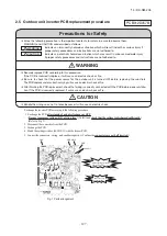
Precautions for safety

Never do it under any circumstances.

Always do it according to the instruction.

1. BEFORE BEGINNING INSTALLATION 

(Check that the models, power source specifications, piping, wiring are correct.)


Indoor unit 

Remote control


Connection OK/NO

FD○△△KXE6   

RC-E3(2 cores), RC-E4(2 cores), RC-E5 (2 cores), RC-EX1A (2 cores) 

OK

FD○A△△KXE4R, KXE4BR, KXE5R 

RC-E1R(3 cores) 

NO

FD○A△△KXE4, KXE4(A), KXE4A 

RC-E1(3 cores) 

NO

Notabilia

(1) Limitation on use of pipes

PSC012D031B

Outdoor unit capacity

FDC224–1000KXZXE1

Read these “Precautions for safty” carefully before starting installation work and do it in the proper way.

Safety instructions listed here are grouped into        Warnings   and       Cautions.    If a non-compliant installation method is likely to result in a serious consequence such as death 

or major injury, the instruction is grouped into        Warnings  to emphasize its importance. However, a failure to observe a safety instruction listed under        Cautions     can also 
result in a serious consequence depending on the circumstances. Please observe all these instructions, because they include important points concerning safety. 

The meanings of “Marks” used here are as shown on the right:

When you have completed installation work, perform a test run and make sure that the installation is working properly. Then, explain the customer how to operate and how to take 

care of the air-conditioner according to the user’s manual. Please ask the customer to keep this installation manual together with the user’s manual.

FDC 224, 280 and 335 comply with EN61000-3-3.

For outdoor unit, EN61000-3-2 is not applicable as consent by the utility company or notification to the utility company is given before usage.

When the Additional refrigerant quantity (P

I

) is over the 

following table, please separate the refrigerant line.

Important

Outdoor unit

S+P+

I

 (kg)

224-670

735-1000

45
90

  ●

Do  not  use  any  refrigerant  other  than  R410A.  R410A  will  rise  to  pressure  about  1.6  times  higher  than  that  of  a  conventional 

refrigerant.

  A cylinder containing R410A has a pink indication mark on the top.

  ●

A  unit  designed  for  R410A  has  adopted  a  different  size  indoor  unit  operation  valve  charge  port  and  a  different  size  check  joint 

provided in the unit to prevent the charging of a wrong refrigerant by mistake.  The processed dimension of the flared part of a 

refrigerant pipe and a flare nut's parallel side measurement have also been altered to raise strength against pressure.  Accordingly, 

you are required to arrange dedicated R410A tools listed in the table on the right before installing or servicing this unit.

  ●

Do  not  use  a  charge  cylinder.  The  use  of  a  charge  cylinder  will  cause  the  refrigerant  composition  to  change,  which  results  in 

performance degradation.

  ●

In charging refrigerant, always take it out from a cylinder in the liquid phase.

  ●

All indoor units must be models designed exclusively for R410A.  Please check connectable indoor unit models in a catalog, etc.  (A 

wrong indoor unit, if connected into the system, will impair proper system operation)

For a normal installation, leave a 10 
mm or wider space on both sides of 
the unit (L5 and L6) as workspace.
It is also possible to install at a 0mm 
interval (continuous installation) with 
future renewal, etc. in mind.

For your information:

the footprint of an outdoor unit is 
1350x720 for all models throughout 
the series (280–560).

WARNING

CAUTION

Use the circuit breaker for all pole with correct  capacity.

Using the incorrect circuit breaker, it can cause the unit malfunction and fire.

Take care when carrying the unit by hand.

If the unit weights more than 20kg, it must be carried by two or more persons. Do not carry by the plastic straps, always use the 

carry handle when carrying the unit by hand. Use gloves to minimize the risk of cuts by the aluminum fins.

Dispose of any packing materials correctly.

Any remaining packing materials can cause personal injury as it contains nails and wood. And to avoid danger of suffocation, be 

sure to keep the plastic wrapper away from children and to dispose after tear it up.

Pay attention not to damage the drain pan by weld spatter when welding work is done near the indoor unit.

If weld spatter entered into the indoor unit during welding work, it can cause pin-hole in drain pan and result in water leakage. To 

prevent such damage, keep the indoor unit in its packing or cover it.

Be sure to insulate the refrigerant pipes so as not to condense the ambient air moisture on them.

Insufficient insulation can cause condensation, which can lead to moisture damage on the ceiling, floor, furniture and any other 

valuables.

Be sure to perform air tightness test by pressurizing with nitrogen gas after completed refrigerant piping work.

If the density of refrigerant exceeds the limit in the event of refrigerant leakage in the small room, lack of oxygen can occur, which 

can cause serious accidents.

Perform installation work properly according to this installation manual.

Improper installation can cause abnormal vibrations or increased noise generation.

Carry out the electrical work for ground lead with care.

Do not connect the ground lead to the gas line, water line, lightning conductor or telephone line's ground lead. Incorrect grounding 

can cause unit faults such as electric shocks and fire due to short-circuiting. Never connect the grounding wire to a gas pipe 

because if gas leaks, it could  cause  explosion  or  ignition.

Earth leakage breaker must be installed

If the earth leakage breaker is not installed, it can cause fire or electric shocks.

Do not use any materials other than a fuse with the correct rating in the location where fuses are to be used.

Connecting the circuit with copper wire or other metal thread can cause unit failure and fire.

Do not install the unit near the location where leakage of combustible gases can occur.

If leaked gases accumulate around the unit, it can cause fire.

Do not install the unit where corrosive gas (such as sulfurous acid gas etc.) or combustible gas (such as thinner and petroleum 

gases) can accumulate or collect, or where volatile combustible substances are handled.

Corrosive gas can cause corrosion of heat exchanger, breakage of plastic parts and etc. And combustible gas can cause fire.

Secure a space for installation, inspection and maintenance specified in the manual. 

Insufficient space can result in accident such as personal injury due to falling from the installation place.

When the outdoor unit is installed on a roof or a high place, provide permanent ladders and handrails along the access route and 

fences and handrails around the outdoor unit.

If safety facilities are not provided, it can cause personal injury due to falling from the installation place.

Do not install nor use the system close to the equipment that generates electromagnetic fields or high frequency harmonics

Equipment such as inverters, standby generators, medical high frequency equipments and telecommunication equipments can 

affect  the  system,  and  cause  malfunctions  and  breakdowns.  The  system  can  also  affect  medical  equipment  and 

telecommunication equipment, and obstruct its function or cause jamming.

Do not install the outdoor unit in a location where insects and small animals can inhabit.

Insects and small animals can enter the electric parts and cause damage or fire. Instruct the user to keep the surroundings clean.

Do not use the base flame for outdoor unit which is corroded or damaged due to long periods of operation.

Using an old and damage base flame can cause the unit falling down and cause personal injury.

Do not install the unit in the locations listed below

t

Locations where carbon fiber, metal powder or any powder is floating.

t

Locations where any substances that can affect the unit such as sulphide gas, chloride gas, acid and alkaline can occur.

t

Vehicles and ships

t

Locations where cosmetic or special sprays are often used.

t

Locations with direct exposure of oil mist and steam such as kitchen and machine plant.

t

Locations where any machines which generate high frequency harmonics are used.

t

Locations with salty atmospheres such as coastlines

t

Locations with heavy snow (If installed, be sure to provide base flame and snow hood mentioned in the manual)

t

Locations where the unit is exposed to chimney smoke

t

Locations at high altitude (more than 1000m high)

t

Locations with ammonic atmospheres (e.g. organic fertilizer).

t

Locations with calcium chloride (e.g. snow melting agent).

t

Locations where heat radiation from other heat source can affect the unit

t

Locations without good air circulation.

t

Locations with any obstacles which can prevent inlet and outlet air of the unit 

t

Locations where short circuit of air can occur (in case of multiple units installation)

t

Locations where strong air blows against the air outlet of outdoor unit

It can cause remarkable decrease in performance, corrosion and damage of components, malfunction and fire.

Do not install the outdoor unit in the locations listed below.

t

Locations where discharged hot air or operating sound of the outdoor unit can bother neighborhood.

t

Locations where outlet air of the outdoor unit blows directly to an animal or plants. The outlet air can affect adversely to 

the plant etc.

t

Locations where vibration can be amplified and transmitted due to insufficient strength of structure.

t

Locations where vibration and operation sound generated by the outdoor unit can affect seriously.

    (on the wall or at the place near bed room)

t

Locations where an equipment affected by high harmonics is placed. (TV set or radio receiver is placed within 5m)

t

Locations where drainage cannot run off safely.

It can affect surrounding environment and cause a claim

Do not use the unit for special purposes such as storing foods, cooling precision instruments and preservation of animals, plants or 

art. It can cause the damage of the items.

Do not touch any buttons with wet hands

It can cause electric shocks

Do not shut off the power supply immediately after stopping the operation.

Wait at least 5 minutes, otherwise there is a risk of water leakage or breakdown.

Do not control the system with main power switch.

It can cause fire or water leakage. In addition, the fan can start unexpectedly, which can cause personal injury.

Do not touch any refrigerant pipes with your hands when the system is in operation.

During operation the refrigerant pipes become extremely hot or extremely cold depending the operating condition, and it can cause 

burn injury or frost injury.

Do not operate the outdoor unit with any article placed on it.

You may incur property damage or personal injure from a fall of the article.

Do not step onto the outdoor unit.

You may incur injury from a drop or fall.

Installation must be carried out by the qualified installer.    

If you install the system by yourself, it may cause serious trouble such as water leaks, electric shocks, fire and personal injury, 

as a result of a system malfunction.     

Install the system in full accordance with the instruction manual. 


Incorrect installation may cause bursts, personal injury, water leaks, electric shocks and fire.     

Use the original accessories and the specified components for installation.     

If parts other than those prescribed by us are used, It may cause fall of the unit, water leaks, electric shocks, fire, refrigerant 

leak, substanard performance, contrl failure and personal injury.

When installing in small rooms, take prevention measures not to exceed the density limit of refrigerant in the event of leakage 

accordance with ISO5149.

Consult the expert about prevention measures. If the density of refrigerant exceeds the limit in the event of leakage, lack of 

oxygen can occur, which can cause serious accidents.     

Ventilate the working area well in the event of refrigerant leakage during installation. 


If the refrigerant comes into contact with naked flames, poisonous gas is produced. 


After completed installation, check that no refrigerant leaks from the system. 

If refrigerant leaks into the room and comes into contact with an oven or other hot surface, poisonous gas is produced. 

Hang up the unit at the specified points with ropes which can support the weight in lifting for portage. And to avoid jolting out 

of alignment, be sure to hang up the unit at 4-point support.

An improper manner of portage such as 3-point support can cause death or serious personal injury due to falling of the unit.

Install the unit in a location with good support. 


Unsuitable installation locations can cause the unit to fall and cause material damage and personal injury. 


Ensure the unit is stable when installed, so that it can withstand earthquakes and strong winds.    

Unsuitable installation locations can cause the unit to fall and cause material damage and personal injury. 


The electrical installation must be carried out by the qualified electrician in accordance with "the norm for electrical work" 

and "national wiring regulation", and the system must be connected to the dedicated circuit.     

Power supply with insufficient capacity and incorrect function done by improper work can cause electric shocks and fire.

Be sure to shut off the power before starting electrical work. 

Failure to shut off the power can cause electric shocks, unit failure or incorrect function of equipment. 


Be sure to use the cables conformed to safety standard and cable ampacity for power distribution work.  


Unconformable cables can cause electric leak, anomalous heat production or fire.   


Use  the  prescribed  cables  for  electrical  connection,  tighten  the  cables  securely  in  terminal  block  and  relieve  the  cables 

correctly to prevent overloading the terminal blocks. 


Loose connections or cable mountings can cause anomalous heat production or fire. 


Arrange the wiring in the control box so that it cannot be pushed up further into the box. Install the service panel correctly.

Incorrect installation may result in overheating and fire.

In connecting the power cable, make sure that no anomalies such as dust deposits, socket clogging or wobble are found and 

insert the plug securely.

Accumulation of dust, clogging on the socket, or looseness of plugging can cause electric shocks and fire.

Be sure not to reuse existing refrigerant pipes 


Conventional refrigerant oil or chlorine contained in the conventional refrigerant which is remaining in the existing refrigerant 

pipes  can  cause  deterioration  of  refrigerant  oil  of  new  unit.  And  1.6  times  higher  pressure  of  R410A  refrigerant  than 

conventional one can cause burst of existing pipe, personal injury or serious accident. 


Do not perform brazing work in the airtight room 


It can cause lack of oxygen. 


Use the prescribed pipes, flare nuts and tools for R410A.    

Using existing parts (for R22 or R407C) can cause the unit failure and serious accidents due to burst of the refrigerant circuit.

Tighten the flare nut by using double spanners and torque wrench according to prescribed method. Be sure not to tighten the 

flare nut too much. 

Loose flare connection or damage on the flare part by tightening with excess torque can cause burst or refrigerant leaks 

which may result in lack of oxygen.     

Do not open the service valves for liquid line and gas line until completed refrigerant piping work, air tightness test and 

evacuation.

If the compressor is operated in state of opening service valves before completed connection of refrigerant piping work, you 

may incur frost bite or injury from an abrupt refrigerant outflow and air can be sucked into refrigerant circuit, which can cause 

burst or personal injury due to anomalously high pressure in the refrigerant.

Do not put the drainage pipe directly into drainage channels where poisonous gases such as sulphide gas can occur.

Poisonous gases will flow into the room through drainage pipe and seriously affect the user's health and safety. It can also 

cause the corrosion of the indoor unit and resultant unit failure or refrigerant leak.

Only use prescribed optional parts. The installation must be carried out by the qualified installer.    

If you install the system by yourself, it can cause serious trouble such as water leaks, electric shocks, fire. 


Do not perform any change of protective device itself or its setup condition     

The forced operation by short-circuiting protective device of pressure switch and temperature controller or the use of non 

specified component can cause fire or burst. 


Be sure to switch off the power supply in the event of installation, inspection or servicing. 


If the power supply is not shut off, there is a risk of electric shocks, unit failure or personal injury due to the unexpected start 

of fan.

Consult the dealer or an expert regarding removal of the unit. 

Incorrect installation can cause water leaks, electric shocks or fire. 


Stop the compressor before closing valve and disconnecting refrigerant pipes in case of pump down operation.

If disconnecting refrigerant pipes in state of opening service valves before compressor stopping, you may incur frost bite or 

injury from an abrupt refrigerant outflow and air can be sucked, which can cause burst or personal injury due to anomalously 

high pressure in the refrigerant circuit.

Ensure that no air enters in the refrigerant circuit when the unit is installed and removed. 


If air enters in the refrigerant circuit, the pressure in the refrigerant circuit becomes too high, which can cause burst and 

personal injury.

Do not run the unit with removed panels or protections     

Touching  rotating  equipments,  hot  surfaces  or  high  voltage  parts  can  cause  personal  injury  due  to  entrapment,  burn  or 

electric shocks.     

Be sure to fix up the service panels.     

Incorrect fixing can cause electric shocks or fire due to intrusion of dust or water. 

Do not perform any repairs or modifications by yourself. Consult the dealer if the unit requires repair. 

If you repair or modify the unit, it can cause water leaks, electric shocks or fire.

(   ): In case it is the promised installation location that the outdoor unit is 

used on conditions with the ambient temperature of 43ºC or more.

(   ): In case it is the promised installation location that the 

outdoor unit is used on conditions with the ambient 
temperature of 43ºC or more.

Summary of Contents for FDC1000KXZXE1

Page 1: ...4 KX DB 206 Note VRF INVERTER MULTI SYSTEM AIR CONDITIONERS KXZ Outdoor units Single use Used also for combination FDC224KXZXE1 280KXZXE1 335KXZXE1 Combination use FDC450KXZXE1 500KXZXE1 560KXZXE1 615KXZXE1 670KXZXE1 735KXZXE1 800KXZXE1 850KXZXE1 900KXZXE1 950KXZXE1 1000KXZXE1 Hi COP series ...

Page 2: ... PROCEDURE 67 2 1 Basics of troubleshooting 67 2 2 Explanation of troubleshooting 68 2 3 Contents of troubleshooting 69 2 4 Outdoor unit control PCB replacement procedure 125 2 5 Outdoor unit inverter PCB replacement procedure 127 2 6 Outdoor unit transistor module replacement procedure 129 3 ELECTRICAL WIRING 132 4 PIPING SYSTEM 134 5 APPLICATION DATA 136 5 1 Installation of outdoor unit 136 5 2 ...

Page 3: ... set temp button Displays the temperature which is set currently Tap this button to change the set temperature Change operation mode button Displays the operation mode which is selected currently Tap this button to change the operation mode Timer button Displays simplified contents of the timer which is set currently When two or more timers are set contents of the timer which will be operated imme...

Page 4: ...justment mode Cover AIR CON No button Display the indoor unit number connected to this remote control CHECK button This button is used at servicing TEST button This button is used during test operation Weekly timer display Displays the settings of the weekly timer Operation setting display area Displays setting temperature airflow volume operation mode and oparation message Operation check indicat...

Page 5: ...n this is pressed once again it stops operating Used to swing the louver Every time this button is pressed displays switch as below Sets room temperature by pressing or button Sets time when setting the time Used to cancel the TIMER SETTINGS Used to reset the microcomputer Indicates the selected airflow volume Indicates when ON TIMER is set Indicates the ON TIMER setting time Nothing displayed whe...

Page 6: ...rd 4 digit number TOP screen Menu screen 1 Menu screen 3 Service password input Tap the Menu button on the TOP screen Main menu screen is displayed Tap the Service Maintenance on the menu screen Display the service password input screen Enter the service password 4 digit number TOP screen Menu screen 1 Menu screen 3 Service password input Service maintenance menu 1 Service maintenance menu 2 Servi...

Page 7: ...etting of silent mode is cancelled regardless whether the power failure compensation is effective or not a At power failure Operating stopped If it had been operating under the off timer mode sleep timer mode the state of stop is memorized Although the timer mode is cancelled at the recovery from power failure the setting of weekly timer is changed to the holiday setting for all weekdays b Operati...

Page 8: ...ting is available After the elapse of the set time period the current set temp will be set back to the Set back temp The setting can be done in cooling and heating mode respectively The selectable range of the set time is from 20 min to 120 min 10 min interval Set the Set back temp by 1 interval 6 Filter sign reset メ ニュー 7番目 A 1 Filter sign reset B 2 Setting next cleaning date A 7 Initial settings...

Page 9: ...fan speed setting Valid or Invalid of Auto fan speed setting can be selected B B B B B A A A A Main indoor unit address can be set Only the Main indoor unit can change operation mode and the Sub indoor units dominated by the Main indoor unit shall follow The Main indoor unit can domain 10 indoor units at a maximum 12 Installer settings 13 RC function settings Setting display item 11 Administrator ...

Page 10: ...e of stop is memorized Although the timer mode is cancelled at the recovery from power failure the setting of weekly timer is changed to the holiday setting for all weekdays b Operation mode c Airflow volume mode d Room temperature setting e Louver auto swing stop However the stop position 4 position is cancelled so that it returns to Position 1 f Remote control function items which have been set ...

Page 11: ...indoor unit fan tap at the thermostat ON is retained so far as the thermostat is turned OFF 3 Timer operation a RC EX1A i Sleep timer Set the time from the start to stop of operation The time can be selected in the range from 30 to 240 minutes in the unit of 10 minute Note 1 Enable the Sleep timer setting from the remote control If the setting is enabled the timer operates at every time ii Set OFF...

Page 12: ...in parallel when the times to turn ON and OFF the airconditioner are duplicated the setting of the OFF timer has priority 4 Remote control display during the operation stop When the operation is stopped the power supply is turned ON it displays preferentially the Room temperature Center Remote Filter sign Inspection and Timer operation 5 Hot start Cold draft prevention at heating a Operating condi...

Page 13: ... the indoor heat exchanger temperature detected with ThI R1 or R2 drops to 35 C or lower the speed of indoor fan is changed to the lower tap at each setting ii During the hot keep the louver is kept at the horizontal position b Ending condition When the indoor fan is at the lower tap at each setting it returns to the set airflow volume as the indoor heat exchanger temperature rises to 45 C or high...

Page 14: ...vent the cold start The louver position display LCD continues to show the display which has been shown before entering this control iii Louver free stop control When the louver free stop has been selected with the indoor function of wired remote control POSITION the louver motor stops when it receives the stop signal from the remote control If the auto swing signal is received from the remote cont...

Page 15: ... including stop this control is stopped immediately and the operating condition is restored v When the Fan OFF is selected the fan on the indoor unit of which the thermostat has been turned OFF is turned OFF The same occurs also when the remote control sensor is effective d Fan control during cooling thermostat OFF i Following fan controls during the cooling thermostat OFF can be selected with the...

Page 16: ...s after the compressor ON 1 OFF OFF 3 minutes delay Thermostat OFF in the condition of 9 Compressor Indoor unit A Thermostat Indoor unit B Thermostat 11 Drain pump control a This control is operated when the inverter frequency is other than 0 Hz during the cooling operation and automatic cooling and dehumidifying operations b Drain pump ON condition continues for 5 minutes even when it enters the ...

Page 17: ...ending on each operating condition 13 Operation check drain pump test run operation mode a If the power is turned on by the dip switch SW7 1 on the indoor PCB when electric power source is supplied it enters the mode of operation check drain pump test run It is ineffective prohibited to change the switch after turning power on b When the communication with the remote control has been established w...

Page 18: ...ps E6 18 External input output control CnT or CnTA Be sure to connect the wired remote control to the indoor unit Without wired remote control remote operation by CnT is not possible to perform CnT CnTA Operation output CnT 2 XR1 Heating output CnT 3 XR2 Thermostat ON output CnT 4 XR3 Error output CnT 5 XR4 Remote operation input CnT 6 Volt free contact XR1 1 2 3 4 5 6 XR3 XR4 CnT Blue 12V XR2 Opt...

Page 19: ...he indoor function setting of Level input Factory default or Pulse input is selected by the function for External input of the wired remote control operation status will be changed as follows i In case of Level input setting Factory default Input signal to CnT 6 or CnTA is OFF ON unit ON Input signal to CnT 6 or CnTA is ON OFF unit OFF Operation is not inverted ON ON OFF OFF OFF ON ON ON ON Remote...

Page 20: ... key switch is ON CnT 6 or CnTA ON Operation permission start stop operation of the unit from the wired remote control becomes available When card key switch is OFF CnT 6 or CnTA OFF Operation prohibition the unit stops operation in conjunction with OFF signal and start stop operation of the unit from the wired remote control becomes not available 2 In case that Operation permission prohibition mo...

Page 21: ...e input is set for the indoor unit function If the external input is changed OPEN CLOSE operation modes are inverted Cooling Heating or Heating Cooling Operation Operation Operation Stop Stop Stop Stop Operation prohibition Operation prohibition Operation prohibition Operation prohibition Operation prohibition Operation prohibition Operation permission Operation permission Operation permission Ope...

Page 22: ...is installed at the ceiling where warm air tends to accumulate the setting can be changed with the wired remote control indoor unit function The compressor and the heater are turned ON OFF at one of the setting temperature 3 2 or 1 C in order to improve the feeling of heating The setting temperature however has the upper limit of 30 C Compressor Compressor Standard Operation Stop Setting temperatu...

Page 23: ...5 C unit goes thermo OFF 30 Auto fan speed control RC EX1A only In order to reach the room temperature to the set temperature as quickly as possible the airflow rate is increased when the set temperature of thermostat differs largely from the return air temperature According to temperature difference be tureen set temperature and return air temperature indoor fan tap are controlled automalically A...

Page 24: ...ning pulse control Remote control command Remote control command Remote control command Intermittent operation Inverter cooling fan FMC1 Solenoid valve 20UF Magnetic contactor CM1 52X1 Solenoid valve SV1 Crankcase heater CH1 Notes 1 ON OFF ON or OFF 2 1 The EEVH1 2 of master unit are fully opened and those of slave unit are fully closed 3 2 When the unit is stopped from cooling operation the EEVH1...

Page 25: ...ng in outdoor units 0 1 CM1 0rps 20 120rps 2 Single use Model 280 335 CM1 Range of the compressor operation speed relative to load is as follows System load range 0 1 Local load range 0 1 CM1 0rps 20 120rps 3 2 outdoor units combination use Model 450 Master unit Slave unit CM01 CM11 CM1 CM1 Range of the compressor operation speed relative to load is as follows Following table is applicable when CM...

Page 26: ... 6 3 outdoor units combination use Model 735 Master unit Slave unit 1 Slave unit 2 CM01 CM11 CM1 CM21 CM1 CM1 Range of the compressor operation speed relative to load is as follows Following table is applicable when CM01 starts initially System load range 0 1 2 3 Local load range 0 1 1 1 Master unit CM01 0rps 20 112rps 52 112rps 52 120rps Slave unit 1 CM11 0rps 0rps 52 112rps 52 120rps Slave unit ...

Page 27: ...SV í USV í USV Slave unit 1 CM11 0rps 0rps í USV í USV Slave unit 2 CM21 0rps 0rps 0rps í USV Model 224 Master 280 Slave 2 280 Slave 1 Master unit Slave unit 1 Slave unit 2 CM01 CM11 CM1 CM21 CM1 CM1 Range of the compressor operation speed relative to load is as follows Following table is applicable when CM01 starts initially System load range 0 1 2 3 Local load range 0 1 1 1 Master unit CM01 0rps...

Page 28: ... compressor start stop order 1 The compressors will be changed over by determinating the start stop order in each heat load zone 2 In case of single use the starting order of CM1 and CM2 will be changed over on each occasion when the out door unit stops 3 In case of combination use the starting order of CM01 CM11 CM21 and CM02 CM12 CM22 will be changed over on each occation when the master unit or...

Page 29: ...000 11th speed 1100 1100 12th speed 1140 1140 Rated speed of cooling b Outdoor fan control in cooling mode Fan speed is controlled based on the high pressure during cooling dehumidifying detected with PSH and the outdoor air temperature detected with Tho A i Initial fan speed is as follows Initial cooling speed of outdoor fan Outdoor temperature 10 C 10 C Outdoor temperature 15 C 15 C Outdoor temp...

Page 30: ...is shorted 1 When the temperature detected with both outdoor heat exchanger temperature thermistors Tho R1 and Tho R2 is higher than 9ºC 2 Or when 12 minutes have elapsed since defrosting started Cold region setting J14 is open 1 When Tho R1 and Tho R2 9ºC is satisfied after 2 minutes and 30 seconds have elapsed since defrosting started and when either of following conditions is satisfied the defr...

Page 31: ...t cut control stops the compressor The compressor starts automatically 3 minutes after the stop ii If the above control activates 4 times within 15 minutes 52C1 is turned off and the operation is stopped with the error stop State of the error continues for 3 minutes after the error stop The error can be reset by operating the inspection reset from the remote control g Power transistor temperature ...

Page 32: ...ion pipe temperature thermistor anomaly E55 Under dome temperature thermistor anomaly E39 Discharge pipe temperature thermistor anomaly E40 High pressure anomaly E56 Power transitor temperature thermistor anomaly E41 Power transister overheat E58 Anomalous compressor by loss synchronism E42 Current cut E44 Liquid flooding anomaly E59 Compressor startup failure E60 Rotor position detection failure ...

Page 33: ...operation i When the conditions of oil return control are not established ii When the backup operation time has exceeded the limit value d Control after the conditions to prohibit the auto backup operation have been established All compressor stop and the error display E XX is shown on the 7 segment display and the remote control In this state the inspection reset of remote control is effective E ...

Page 34: ...ever regarding the dip switch SW3 2 for automatic backup operation it is invalid during test run operation regardless whether SW3 2 is turned ON valid or OFF invalid In order to check trouble during test run operation d Control during test run If indoor units are normal i Heating operation is performed with SW5 2 OFF while cooling operation is performed with SW5 2 ON ii Indoor EEV control at the e...

Page 35: ...t starting address Specify a starting indoor unit address in automatic address setting The communication plotocol is displayed display only P33 Input number of connected indoor units Specify the number of indoor units connected in the refrigerant system in automatic address setting 7 segment display indication in automatic address setting Name Purpose Factory default Specification Operating side c...

Page 36: ...emote control operation Remote control display Air conditioner operation stop PUSH PUSH PUSH OFF Center Remote ON Shorted Center OFF OFF Open Air conditioner ON OK OFF ON ON OFF OFF ON ON Remote control operation Remote control display Air conditioner operation stop Center Center Center Remote Remote Air conditioner ON OK CnS1 input OFF OFF ON ON OFF OFF ON OFF ON PUSH PUSH PUSH PUSH PUSH Input Cn...

Page 37: ...ol OFF OFF ON ON PUSH PUSH PUSH PUSH c 3 step demand control 14 KX SM 202 OFF OFF ON ON Demand OFF OFF ON ON ON ON OFF OFF Demand This control has priority over the controls of 4 way valve safeguard compressor protective start operation defrost operation oil equalized operation oil return operation pump down operation for replacement Start Stop pump down operation and check operation 1 Starting co...

Page 38: ...r 0 has been transmitted from an indoor unit of Peak cut timer function Normal demand of Item b is not activated This control is performed on the RC EX1A remote control 2 Contents of control Compressor s upper limit speed is restricted according to the demand restriction rate The demand ratio controlled by the restriction rate which is transmitted from an indoor unit If the demand control rate sig...

Page 39: ... are received it enters the silent mode operation under or condition e When silent mode signals from all indoor units become Silent mode end and when silent mode signal input to CnG2 on outdoor unit becomes open the silent mode operation is reset f The operation of silent mode 1 is effective within the following temperature range Cooling Heating Outdoor air temperature Outdoor air temperature i Si...

Page 40: ...tting of outdoor fan snow protection control is saved in the memory of EEPROM and henceforth the outdoor fan is controlled according to the contents of memory vii Contents of outdoor fan snow protection control are retained even if the power is turned off and backed on again d Contents of outdoor fan snow protection control i At the status of all stop or emergency stop if the outdoor air temperatu...

Page 41: ...ewed in following cases At the stop When the P01 setting is changed 3 In the event that agreement of operation mode is lost between indoor units and outdoor units by selecting the first or second priority after determining the operation mode it is changed forcibly to the Fan mode The operation mode LCD flickers to warn the Mode unmatch 4 Example of operation mode selection First unit s operation m...

Page 42: ... Cooling heating unmatched When unmatch occurs among indoor units it can be reset by either one of followings If the operation mode of outdoor unit is matched with that of indoor unit If the operation mode is changed to Fan or Stop on the indoor units on which Cooling heating is unmatched Indoor unit 0 Stop Fan Fan ON Indoor unit 1 Stop Heating Heating ON Indoor unit 0 Stop Cooling Invalid operati...

Page 43: ...ch is displayed on the remote control etc and it is changed to the fan operation P18 1 It is operated with the forced cooling heating operation mode Setting temperature for cooling 28 Setting temperature for heating 20 5 Emergency stop control When one of indoor units receives the emergency stop signal through CnT terminal on the indoor control PCB from the device like as refrigerant leakage detec...

Page 44: ...ed in the field The maximum load of relay is LY2F Omron f The output connectors CnH CnY to be connected to the relays for operation output 52XR and for error output 52XE is mounted on the outdoor control PCB g If CPU goes out of control this function becomes disable h When the automatic backup operation is effective there is no error display for any error on the compressor stopping by detecting it...

Page 45: ... normal if the pump down control switch is reset b Pump down operation can be performed with the operation of 3 dip switches SW5 1 Test run switch SW5 2 Test run operation mode and SW5 3 Pump down switch c Pump down procedure 1 Shut the liquid side service valve on the outdoor units 2 Turn SW5 2 test run operation mode ON cooling 3 Turn SW5 3 pump down switch ON 4 Turn SW5 1 test run switch ON d E...

Page 46: ...utput on CnY and the liquid service valve is shut down if it is connected on CnY The pump down operation for replacement is performed iii Ending condition When starting conditions are lost When the pump down operation has ended b Status 2 Emergency stop operation i Starting condition When the pump down operation has ended in the status 1 ii Contents of control ON is output to CnZ1 and the gas serv...

Page 47: ...alve to shut liquid pipe 3 Output for valve to shut liquid pipe CNY Wiring part no PCZ006A051A Output for valve to shut gas pipe CNZ1 Wiring part no PCZ006A051B Need to use DC12V relay OMRON LY2F equivalent for output the CNY CNZ1 Keep less than 150mA at maximum with all CNY CNZ1 CNH ...

Page 48: ...door units which are operating with the thermostat ON a Correction of target high low pressure i Starting condition either of or When the external input function assignment P07 P10 Multi system energy save control Valid When 7 segment P69 Multi system energy save control I ON if the external input function assignment P07 P10 is not assigned this control ii Contents of control During the outdoor un...

Page 49: ...ed this control ii Contents of control Compressor upper limit speed is the value obtained by multiplying with the upper limit speed restriction rate ac cording to the thermostat ON capacity The upper limit restriction rate is divided to the following 3 steps according to each setting of P16 as follows Following controls supersede this control 4 way valve safeguard Defrost operation Oil return oper...

Page 50: ... displayed it jumps to the code No C10 9 The data of code No C54 and C55 can be erased independently The compressor cumulative operation time corresponding to the code No selected can be erased reset For resetting of the compressor cumulative operation time after replacement of compressor The resetting method is to select the code C54 or C55 first the compressor cumulative operation time correspon...

Page 51: ... PoE PoS Pump down operation OPE Outdoor unit setting 2 If the state of 1 is reset it is automatically switched to CXX Automatic data display mode 3 When pressing SW8 or SW9 under the state of 1 it switched to CXX However the button input is not done for 10 seconds after switching to CXX the display is changed to the spe cial display according to the priority of the state 1 When Special display oc...

Page 52: ...ear Tho R3 Heat exchanger temp 3 Entrance Front Tho R4 Heat exchanger temp 4 Entrance Rear Tho D1 Discharge pipe temp CM1 Tho D2 Discharge pipe temp CM2 Tho C1 Under dome temp CM1 Tho C2 Under dome temp CM2 Tho P1 Power transistor temp CM1 Tho P2 Power transistor temp CM2 Tho SC Sub cooling coil temp 1 Tho SC Sub cooling coil temp 2 Tho S Suction pipe temp CT1 Current CM1 CT2 Current CM2 EEVH1 Hea...

Page 53: ...NS1 CNS2 CNG1 CNG2 SV8 SV10 52C1 52C2 CH1 0 1 0 1 Order of 100 CNS1 Order of 10 CNS2 Order of 1 CNG1 0 Close 1 Open Order of 100 CNG1 Order of 10 SV8 Order of 1 SV10 0 Close 1 Open 0 Close 1 Open Order of 100 CH2 Order of 10 20S Order of 1 20SL SV11 SV13 Order of 100 SV11 Order of 10 Spare Order of 1 SV13 0 Close 1 Open CNZ1 CNH CNY CNZ1 External output CNH Operation output CNY Error output 0 Clos...

Page 54: ...s Protection control status Compressor stop causes Time elapsed after compressor stop cause Protection control causes 1 Compressor error causes 1 Counter Anomalous FMo1 Counter Anomalous FMo2 Counter Indoor outdoor communications error 1 FMo2 operating revolution command 0 999 10min 1 Demand ratio Outdoor operating mode pattern 0 127 1 1 1 Protection control causes 2 1 Protection control causes 3 ...

Page 55: ...80 Factory default 000 040 060 080 080 Factory default 000 040 060 080 080 Factory default 000 040 060 080 0 Factory default 0 3 0 Factory default 0 9 P07 P08 P09 P10 Many steps demand setting 2nd step demand Many steps demand setting 3nd step demand Multi system energy save control II 1 P17 P18 P19 P30 P31 P32 P33 P34 0 1 1 1 1 Superlink communication status Start automatic address setting Input ...

Page 56: ...tion control During HP protection 1 Spare 2 During LP protection 3 During discharge temperature 4 During specific pressure protection 5 During under dome temperature protection 6 During current safe protection 7 During power transistor temperature protection 8 22 Code No Remarks Contents of display Data display range Minimum unit AUX AUE A01 A02 A03 A04 Auto address setting on Indoor unit address ...

Page 57: ... 23 Liquid flooding anomaly CM1 24 Liquid flooding anomaly CM2 25 Spare 26 Fan Compressor Communication error Outdoor DC fan motor anomaly FMo1 30 Outdoor DC fan motor anomaly FMo2 31 Current cut CM1 32 Current cut CM2 33 Power transistor overheat CM1 34 Power transistor overheat CM2 35 Compressor startup failure CM1 36 Compressor startup failure CM2 37 Communication error between inverter PCB and...

Page 58: ...g of Operation Data For the purpose to investigate the cause of trouble in the field the operation data are always saved in the memory and if the trouble occurs the data writing is stopped and the operation data prior to the trouble occurrence are recorded These data can be retrieved to personal computer through RS232C connector on the outdoor control PCB and utilized for probing the cause i Opera...

Page 59: ...75 35 75 35 75 A D value A D value A D value A D value 2 2 2 2 Heat exchanger temp 1 Exit Front Heat exchanger temp 2 Exit Rear Heat exchanger temp 3 Entrance Front Heat exchanger temp 4 Entrance Rear 07 08 09 10 20 140 20 140 15 90 15 90 A D value A D value A D value A D value 1 1 1 1 Tho D1 Discharge pipe temp CM1 Tho D2 Discharge pipe temp CM2 Tho C1 Under dome temp CM1 Tho C2 Under dome temp C...

Page 60: ...tion number Indoor unit connection capacity Indoor unit thermostat ON number Indoor unit cooling thermostat ON capacity Required Hz total Suction pipe side 17 40 75 A D value 2 Receiver liquid surface detection temp 1 spare 22 0 00 5 00 A D value 1 High pressure sensor 23 0 00 2 00 A D value 1 Low pressure sensor 29 0 65535 2 Indoor unit heating thermostat ON capacity Stop Heating Cooling 0 1 2 30...

Page 61: ...le EEVH2 opening angle EEVSC opening angle 0 65535 1pulse 2 EEVD opening angle 54 Target cooling low pressure of compressor 0 00 2 00 0 01MPa 1 Target heating high pressure of compressor 0 00 4 15 0 01MPa 2 1ºC 0 1ºC 59 60 61 1 1 1 Spare Spare Spare 1 63 1 Output of relay 64 1 Output of relay Bit1 Bit2 Bit3 Bit4 Bit5 Bit6 Bit7 Bit0 Bit1 Bit2 Bit3 Bit4 Bit5 Bit6 Bit7 Bit0 Bit1 Bit2 Bit3 Bit4 Bit5 B...

Page 62: ...6 2 Oil equalized operation 7 1 Oil equalized operation 7 2 Oil equalized operation 8 1 Oil equalized operation 8 2 None Oil return cooling 0 1 10 20 30 41 42 51 52 61 62 71 72 81 82 0 1 2 0 2 1 Control status Defrost kinds defrost status Control status Oil return Oil return gas cycle 0 11 12 13 14 21 22 23 24 31 32 33 34 Thermal condition defrost status 1 Thermal condition defrost status 2 Therma...

Page 63: ...ntrol status 3 Bit0 Auto backup operation Bit1 Bit2 Bit3 Bit4 Bit5 Bit6 Bit7 Spare Spare Spare Spare 0 Count 1 Count up Spare Spare Spare 0 Normal 1 Practice 0 Count 1 Count up 0 Count 1 Count up 0 Count 1 Count up 0 Count 1 Count up 0 Count 1 Count up 0 Count 1 Count up 81 0 127 1 hour 1 Backup cumulative time 82 0 2 1 Check operation status 83 Spare Bit0 Bit1 Bit2 Bit3 Bit4 Bit5 Bit6 Bit7 0 Norm...

Page 64: ...ho D2 counter 0 5 Control status Cut off sensor counter 0 5 Control status Liquid flooding anomaly counter 101 102 Counter Current cut CM2 103 0 255 Counter Power transistor overheat CM1 104 0 255 Counter Power transistor overheat CM2 105 0 255 Counter Compressor startup failure CM1 106 0 255 Counter Compressor startup failure CM2 107 0 255 Counter Anomalous compressor by loss of synchronism CM1 1...

Page 65: ...s 2 Bit0 Bit1 Spare 0 Normal 1 Practice 0 Normal 1 Practice Spare 63H1 Bit0 Bit1 0 OFF 1 ON 124 1 External input Spare CNS1 CNS2 CNG1 CNG2 125 1 DIP SW SW 3 SW3 1 SW3 2 SW3 3 SW3 4 SW3 5 SW3 6 SW3 7 SW3 8 126 1 DIP SW SW 4 SW4 1 SW4 2 SW4 3 SW4 4 SW4 5 SW4 6 SW4 7 SW4 8 Bit0 Bit1 Bit2 Bit3 127 1 DIP SW SW 5 SW5 1 SW5 2 SW5 3 SW5 4 0 OFF 1 ON 0 OFF 1 ON 0 OFF 1 ON 0 OFF 1 ON 0 OFF 1 ON 0 OFF 1 ON 0...

Page 66: ...0 50 1 Heating setting 1 Target exit temperature 1 C 133 3 15 2 75 1 Heating setting 2 Target of high temperature 0 05MPa 134 30 38 1 Heating setting 3 Judgment temperature 1 C 135 0 9 1 CNS1 function assignment 136 0 9 1 CNS2 function assignment 137 0 9 1 CNG1 function assignment 138 0 9 1 CNG2 function assignment 139 0 9 1 External output function assignment function assignment 140 0 255 1 State...

Page 67: ...Cooling Pump down SW Normal Pump down SL selector New SL Auto Old SL Capacity measurement mode Capacity measurement mode Capacity measurement mode Data erase write 7 segment display code No increasing order of 1 7 segment display code No increasing order of 10 Model selection Spare Master slave unit setting address Master slave unit setting address Power supply voltage selection Power supply volta...

Page 68: ...ous SL Normal Normal 0 Automatic Remarks Indoor unit address No Order of 10 Indoor unit address No Order of 1 Outdoor unit address No Order of 10 Outdoor unit address No Order of 1 Superlink selection Indoor unit address No Order of 100 0 9 0 9 0 9 0 9 Code Input Default setting 0 OFF 1 ON P15 0 0 0 0 1 P22 0 0 0 0 0 P28 1 0 0 0 0 P36 0 1 0 0 0 P45 0 0 1 0 0 P56 0 1 1 0 0 P71 0 0 0 1 0 P90 0 1 0 1...

Page 69: ...ring etc Is the failure related to any hardware parts SV main body coil capillary check valve sensor etc Is it a major component Compressor inverter PCB and outdoor DC fan motor Is it a failure of electrical component Error on indoor unit or outdoor unit Indoor unit Outdoor unit Is the remote control connected Was the power supply reset after the error occurred Check and write down the momentary d...

Page 70: ...re to wait for 3 minutes after turning the power circuit breaker off Disconnect the fan motor wires Both the power cable and control wires Turn the power circuit breaker OFF Wait 3 minutes Check whether DC15V between of CNI1 on the control PCB is detected Check E41 42 45 48 Connect the wires of fan motor 1 or 2 Power ON Test run switch ON If DC15V is detected primary check is completed Return to a...

Page 71: ... on power supply at primary side Site setting error 103 E36 E36 1 Discharge pipe temperature error Tho D1 System error 104 E37 E37 1 2 E37 4 5 E37 5 6 Outdoor heat exchanger temperature thermistor Tho R and subcooling coil temperature thermistor Tho SC H anomaly Thermistor wire breakage 105 E38 E38 Outdoor air temperature thermistor anomaly Tho A Thermistor wire breakage 106 E39 E39 1 Discharge pi...

Page 72: ...idifying or heating operation from remote control Note 1 Outdoor 35ºC Indoor 27ºCDB 19ºCWB It is normal This unit is designed to start in the soft start mode by detecting the compressor under dome temperature when it restart after power reset It is necessary to replace to higher capacity unit or to install additional unit Compressor refrigerant oil protective control at starting is activated For t...

Page 73: ...ing operation from remote control Note 1 Outdoor 7ºC Indoor 20ºCDB It is normal This unit is designed to start in the soft start mode by detecting the compressor under dome temperature when it restart after power reset It is necessary to replace to higher capacity unit or to install additional unit Compressor refrigerant oil protective control at starting is activated For the contents of control r...

Page 74: ...esistance may drop to a few M Ω because of refrigerant migrated in the compressor When the earth leakage breaker is activated at lower insulation resistance check the following points 6 hours after power ON check if the insulation resistance recovers to normal When power ON crankcase heater heat up compressor and evaporates the refrigerant migrated in the compressor Check if the earth leakage brea...

Page 75: ...ate looseness Prevent the vibration from transmitting to wall and etc by fixing pipes on the wall tightly or wrapping rubber cushion around the pipe which goes through the hole in the wall or applying other appropriate means Strength of ceiling wall floor etc may be insufficient Review the installation place or apply reinforcement to increase the strength Check for leaning of installed unit or inc...

Page 76: ... liquid flows through inside of piping of air conditioner It is likely to occur particularly during cooling or defrosting in the heating mode It is normal The noise vibration occurs when the refrigerant starts or stops flowing It is normal When the defrosting starts or stops during heating mode the refrigerant flow is reversed due to switching 4 way valve This causes a large change in pressure whi...

Page 77: ...erant Intrusion of air nitrogen etc In such case it is necessary to recover refrigerant vacuum dry and recharge refrigerant Since there could be many causes of noise vibration the above may not cover all In such case check the conditions when where how the noise vibration occurs according to following check points and ask our consultation Indoor outdoor unit Cooling heating fan mode Startup stop d...

Page 78: ...etting YES NO Does the louver link press LS till crick sound can be heard NO NO YES NO NO YES In cases of FDTW FDTS and FDTQ Does the louver operate when power on Note 1 LM Louver motor 2 LS Limit switch YES NO NO NO NO YES YES Operate after waiting for more than 1 minute It is normal if LM can be stopped by pressing LS two times In cases of FDT FDTC FDE and FDK Check the remote control whether it...

Page 79: ... supply between of CNW0 OK Is DC5V detected between of CNW2 Is power supply to FM LM and etc OK Note 1 Check the fuse at the power supply side 1 2 3 4 Model equipped with transformer Tr㧵 Models other than shown at left Is DC18V or higher detected between Red Red CNW2 at the transformer secondary side Outdoor Noise filter PCB anomaly Replace it Wrong wiring or broken wires between outdoor and indoo...

Page 80: ...ry side Is DC18V detected between of CNW2 Disconnect the remote control wires NO Is DC15V or higher detected between X Y of indoor unit terminal block Model equipped with transformer Tr㧵 Models other than shown at left YES YES YES YES NO NO YES NO NO Correct it Replace wires Replace remote control Indoor power PCB anomaly Replace it Indoor control PCB anomaly Replace it Replace transformer Indoor ...

Page 81: ...IT Replace noise filter PCB Connect wires correctly Indoor control PCB anomaly Replace it Indoor outdoor control PCB anomaly Replace it Remote control anomaly Replace it Breakage of wires for remote control Replace it Correct the connecting wires between indoor and outdoor units Outdoor control PCB anomaly Replace it Breakage of connecting wire Noise Indoor control PCB anomaly Replace it 2 Error d...

Page 82: ...S NO Isn t there any short circuit between phases of noise filter Isn t there any crack or damage on power transistor module or diode stack Isn t there any anomaly on reactor Replace noise filter Replace reactor Replace inverter PCB Replace fuse 2 Error detection method 3 Condition of error displayed 4 Presumable cause Fuse blown Noise filter anomaly Anomalous connection of wire between PCBs Indoo...

Page 83: ... Is The fuse on indoor control PCB OK Is AC18V or higher is detected between Red Red at secondary side of indoor transformer 1 Is DC10 11V between X Y at indoor control PCB side when removing remote control Note 1 Model equipped with transformer Tr㧵 only Fuse blown Replace fuse Transformer anomaly Remote control wire short circuited Remote control anomaly Indoor control PCB anomaly Remote control ...

Page 84: ...tected between L1 L2 L2 L3 L3 L1 respectively at outdoor terminal block Is AC220 240V detected between L N at indoor terminal block NO NO NO NO NO YES YES YES YES YES YES A Refer next page WAIT Indoor control PCB anomaly Replace it Indoor control PCB anomaly Replace it Remote control anomaly Replace it Breakage of wires for remote control Replace it Correct the connecting wires between indoor and ...

Page 85: ...ere any anomaly on outdoor fan motor Once turn OFF the breaker and turn ON it again at 3 minutes after power OFF Does it become normal Check inverter before replacement of 52C NO NO NO NO NO NO YES YES YES YES YES YES A B Refer next page From previous page Normal Malfunction by temporary noise Replace noise filter Connect the connecting wire properly Correct connection In case of breakage of wire ...

Page 86: ...eplace electrolytic capacitor Replace reactor Isn t there any short circuit between phases at input terminal of inverter PCB Isn t there any crack or damage on power transistor module or diode stack Isn t there any anomaly on reactor Isn t there any anomaly on electrolytic capacitor NO NO NO NO NO B YES YES YES YES YES From previous page 2 Error detection method 3 Condition of error displayed 4 Pr...

Page 87: ... detected at remote control terminal Is DC10V or higher between X Y wires detected when removing remote control Are connecting wires between indoor and outdoor units connected properly Remote control anomaly Remote control anomaly Correct connecting wire Indoor control PCB anomaly 2 Error detection method 3 Condition of error displayed 4 Presumable cause Fuse blown Noise filter anomaly Anomalous c...

Page 88: ... Note 2 Does the remote control displays Internal check ON even after 3 minutes Reset power supply 2 1 NO Malfunction by temporary noise Check peripheral environment Indoor control PCB anomaly Replace it Remote control anomaly Replace it 2 Error detection method When normal communication between remote control and indoor unit is interrupted for more than 2 minutes Detectable only with the remote c...

Page 89: ... supply is reset addresses will not be confirmed YES NO YES NO YES NO Review number of connected units Correct indoor unit address setting Implement test run Replace indoor control PCB Before replacement confirm whether the rotary switch for address setting is not damaged It was experienced that No 5 on rotary switch was not recognized 2 Error detection method More than 129 indoor units are connec...

Page 90: ...es to E5 In both cases check signal line wired locally YES Is the outdoor unit address set on the indoor unit OK YES Is the LED on indoor control PCB OK YES Is protective fuse for the Superlink circuit blown NO Does E3 E5 occurs YES NO NO NO YES YES NO NO Temporary malfunction by noise Identify the source of noise and correct it Change to spare circuit Indoor control PCB anomaly Replace it Correct...

Page 91: ...breakage of signal wires between indoor and outdoor units YES NO YES NO YES NO In case that indoor red LED flashes 2 times Repair signal wires Repair signal wires Go to the diagnosis of WAIT 1 Unit is normal Malfunction by temporary noise etc Outdoor control PCB anomaly Network communication circuit anomaly Replace it Unit is normal Malfunction by temporary noise etc 2 Error detection method When ...

Page 92: ...sistance characteristics of indoor heat exchanger temperature thermistor ThI R1 R2 R3 5kΩ at 25ºC Temperature ºC Insert the connector securely Replace thermistor ThI R Replace indoor control PCB 2 Error detection method Detection of anomalously low temperature resistance of ThI R1 R2 R3 3 Condition of error displayed If 50ºC or lower is detected for 5 seconds continuously compressor stops After 3 ...

Page 93: ...al times to prove any poor connection 15 10 5 0 10 30 40 20 50 Temperature sensor resistance k Ω Temperature C 5kΩ at 25 C Insert the connector securely Replace thermistor ThI A Replace indoor control PCB 2 Error detection method Detection of anomalously low temperature resistance of ThI A 3 Condition of error displayed If 50 C or lower is detected for 5 seconds continuously compressor stops After...

Page 94: ...pe slop OK NO YES NO YES NO NO YES Check float switch Check the connection of CNI If it is loose connect it securely Replace indoor control PCB Check optional equipment Correct setting to Humidifier drain motor interlock Indoor control PCB or power PCB FDTC anomaly Replace it Check the wiring of drain motor Correct it Check drain motor 2 Error detection method Float switch is activated 3 Condition...

Page 95: ...Applicable model 5 Troubleshooting All models Diagnosis Countermeasure Aren t more than 17 indoor units connected to one remote control NO YES Remote control anomaly Replace it Reduce to 16 or less units 2 Error detection method When it detects more than 17 of indoor units connected to one remote control 3 Condition of error displayed Same as above 4 Presumable cause Excessive number of indoor uni...

Page 96: ...ing the Master IU address set function of remote control 3 Condition of Error displayed Same as above 4 Presumable cause Same as above Note Is Master IU address set function of remote control used E11 occurs YES Error code Remote control LED Green Red Indoor Content IU IU IU R C In case the wiring is below and Master IU address set is used E11 is appeared Error code Remote control 7 segment displa...

Page 97: ...ror displayed Same as above 4 Presumable cause Mistake in address setting for indoor unit Note Address setting method list Figures in are for Previous Superlink models Models for new Superlink protocol Models for Previous Superlink protocol Indoor unit address setting Outdoor unit address setting Indoor unit address setting Outdoor unit address setting Indoor unit No SW Outdoor unit No SW Outdoor ...

Page 98: ... the fan motor Check power supply voltage Replace fan motor and power PCB Replace fan motor If the anomaly persists after replacing the fan motor replace the indoor control PCB Malfunction by temporary noise 2 Error detection method Detected by revolution speed of indoor fan motor 3 Condition of error displayed When actual revolution speed of indoor fan motor drops to lower than 200min 1 for 30 se...

Page 99: ...he address setting for the master indoor unit correct Correct the address setting of Supply the power to the master Connect the Superlink signal Indoor control PCB anomaly slave indoor unit If it is not the master indoor unit as well Are the Superlink signal wires connected between master and slave indoor units 1 When the address setting for the master indoor unit is not existing in the same Super...

Page 100: ...rgetting to turn OFF SW7 1 after indoor operation check Note Indoor operation check drain pump check mode If the power is ON after SW7 1ON indoor operation check drain pump check mode can be established 1 When the communication between remote control and indoor PCB is established 15 seconds after power ON it goes to indoor operation check 2 When the communication between remote control and indoor ...

Page 101: ...and FDK Remove foreign material Replace the fan motor Check power supply voltage Replace fan motor and power PCB Replace fan motor If the anomaly persists after replacing the fan motor replace the indoor control PCB Malfunction by temporary noise 2 Error detection method Detected by rotation speed of indoor fan motor 3 Condition of error displayed When the actual fan rotation speed does not reach ...

Page 102: ...place indoor control PCB 2 Error detection method Panel switch PS has detected Open for more than 1 second 3 Condition of Error displayed Same as above 4 Presumable cause Defective panel switch Disconnection of wiring Defective indoor control PCB Note Does matter improve if panel switch is turned ON forcibly after resetting error Is grill opened NO YES NO YES YES Are connectors at right inserted p...

Page 103: ... cause Anomalous connection of remote control temperature thermistor Remote control temperature thermistor anomaly Remote control PCB anomaly Note After 10 seconds has elapsed since remote control temperature thermistor was switched from invalid to valid E28 will not be displayed even if the thermistor harness is disconnected or broken However in such case the indoor return air temperature thermis...

Page 104: ... recognized 2 Error detection method When the microcomputer of outdoor control PCB recognizes the duplicated address No by scanning all addresses of outdoor units in the same Superlink system 3 Condition of error displayed When duplicated outdoor unit address No exists in the same Superlink system 4 Presumable cause Mistake in the address setting of outdoor units More than 129 indoor units connect...

Page 105: ...ing It will be useful to persuade the customer why an improvement of power supply is required by showing these data Propose an improvement to the customer Check it as much as possible under the operating conditions for 30 minutes before error occurred Replace outdoor control PCB Check the connection of wire Wait and see without taking any action 2 Error detection method By Checking the power suppl...

Page 106: ...he characteristics are correct by referring the characteristics chart of E39 And if necessary replace the discharge pipe temperature thermistor Check it as much as possible under the operating conditions for 30 minutes before error occurred Wait and see Continue to obtain data if possible Keep connecting the Mente PC Replace outdoor control PCB Replace the coil SV1 Replace the SV1 main body If the...

Page 107: ...ual measured value Insert the connector securely Replace thermistor Tho SC Tho H Tho R Replace outdoor control PCB 2 Error detection method Detection of anomalously low temperature resistance of Tho R or Tho SC or Tho H 3 Condition of error displayed If 50 C or lower is detected for 5 seconds continuously within 2 minutes to 2 minutes 20 seconds after the compressor ON the compressor stops And aft...

Page 108: ...sensed value Compare the temperature on Mente PC with actual measured value Insert the connector securely Replace thermistor Tho A Replace outdoor control PCB 2 Error detection method Detection of anomalously low temperature resistance of Tho A 3 Condition of error displayed If 30 C or lower is detected for 5 seconds continuously within 2 minutes to 2 minutes 20 seconds after the compressor ON the...

Page 109: ...he power on or during operation or stopping Check the sensed value Compare the temperature on Mente PC with actual measured value Insert the connector securely Replace thermistor Tho D1 Replace outdoor control PCB 2 Error detection method Detection of anomalously low temperature resistance of Tho D1 3 Condition of error displayed If 3 C or lower is detected for 5 seconds continuously within 10 min...

Page 110: ...ation If the high pressure sensor PSH fails replace it If the connector is disconnected or the harness is broken correct it Also check whether the high pressure switch is properly mounted or not Check the open N phase on power supply Open operation valve Check it as much as possible under the operating conditions for 30 minutes before error occurred Replace outdoor control PCB Remove clogs Check i...

Page 111: ...ng fan running NO YES NO YES NO Does it repeat after restarting operation YES NO After power OFF After power ON Is power transistor characteristic OK 1 NO YES Are power transistor sensor connectors connected properly Check short circuit broken wire NO Is power transformer attached properly Check tightness of screw heat radiation silicon NO Is 15V detected on inverter PCB 2 YES YES YES If it fails ...

Page 112: ...tion Check pressure for anomaly Wait and see Replace compressor Wait and see Replace compressor on which error occurred initially Replace power transistor Replace power transistor Replace inverter PCB Save data for 30 minutes before stopping in Mente PC Evaluate data 30 minutes earlier YES YES YES YES YES YES NO NO NO NO Power transistor error Short circuited Good If error display of E42 does not ...

Page 113: ... ON the dip switch SW5 4 on the outdoor control PCB However since this tentative solution could cause trouble be sure to correct it as soon as possible Signal wire may be connected to other outdoor unit system Correct the signal wire Correct addresses Either one of addresses is wrong If the address corrected with rotary switch is still wrong replace control PCB Defective rotary switch Before repla...

Page 114: ...O NO NO NO NO NO YES YES YES YES YES YES YES Is the characteristics of Tho C1 OK Check and save the data of operating condition Check the ROM version Confirmation of SV1 operation Correct the connection of refrigerant piping and or signal wiring properly Adjust refrigerant amount properly Replace SV1 Replace the coil of SV1 Replace EEVSC Check the coil of EEVSC Replace the coil of EEVSC Replace Th...

Page 115: ...as much as possible Replace control PCB NO NO NO NO NO NO Isthereshort circuitorbrokenwirebetweendiodemodules YES NO NO YES Is green or red LED flashing or lighting on inverter PCB Save data for 30 minutes before stopping in Mente PC Power ON Is surge suppressor resistor coil broken Power OFF Power OFF YES YES YES NO YES YES YES YES Disconnect harness connected to resistor and check resistance bet...

Page 116: ...Correct signal line In case of automatic address setting signal line cannot be connected to other outdoor unit system Test run Replace outdoor control PCB Rotary switch anomaly Before replacement please confirm whether the rotary switch for address setting is not damaged It was experienced that No 5 on rotary switch was not recognized 2 Error detection method If the signal line of a outdoor unit s...

Page 117: ... E48 2 2 time flash FMO2 Inspect also the fan motor 2 even if it is E48 1 Inspect also the fan motor 1 even if it is E48 2 Replace fan motor Replace inverter PCB on 1 line When inverter PCB is replaced check also items further than 2 see next page Checking of blown surge suppressor resister coil and short circuit on power transistor and diode Replace fan motor Replace inverter PCB Replace faulty f...

Page 118: ... Defective surge suppressor resistor Note 1 Measurement position Between pins 2 3 of IC3 on control PCB If it fails to repeat connect the Mente PC and continue to collect data 1 E48 1 1 time flash FMO1 E48 2 2 time flash FMO2 Inspect also the fan motor 2 even if it is E48 1 Inspect also the fan motor 1 even if it is E48 2 Power OFF From previous page Does speed command voltage of control PCB rise ...

Page 119: ...el of the unit Check whether the service valves are open Correct the connection of low pressure sensor connector Replace low pressure sensor Replace outdoor control PCB Correct the connection of temperature thermistor connector of heat exchanger Replace temperature thermistor of heat exchanger at evaporator side Replace control PCB at evaporator side Replace EEV coil Replace EEV main body or strai...

Page 120: ...hen the compressor is restarted automatically after 3 minutes delay if this anomaly occurs 3 times within 40 minutes 4 Presumable cause Broken thermistor harness or the internal wire of sensing section Check the molded section as well Disconnection of thermistor harness connection connector Outdoor control PCB anomaly Note 1 E55 1 Tho C1 5kΩ at 25 ºC Temperature ºC Tempearture thermistor resistanc...

Page 121: ...the data of operating conditions Check the conditions whether it occurs immediately after the power on or during operation or stopping Check the sensed value Insert the connector securely and restart operation Temporary malfunction by noise Correct if the source of noise is specified Replace sensor PSH PSL Replace outdoor control PCB 2 Error detection method Detection of anomalous pressure voltage...

Page 122: ...occurs immediately after the power on or during operation or stopping Check the sensed value Compare the temperature of Mente PC data with actual measured value Insert the connector securely Replace power transistor temperature thermistor Tho P1 Replace outdoor control PCB 2 Error detection method Detection of anomalously low temperature resistance of Tho P1 3 Condition of error displayed When the...

Page 123: ...possible and operate again Change wire connections on inverter and compressor and operate again Is it initial startup within 1 hour after power ON Is there record of replacement of inverter PCB Is 15 V detected on inverter PCB Check inverter PCB for defect with the checker Other Including checker not available Power transistor error Short circuited Good Check resistance between power transistor mo...

Page 124: ...or If the compressor speed cannot increase 11Hz or higher 3 Condition of error displayed If the compressor fails to startup for 20 times 10 patterns x 2 times continuously 4 Presumable cause Anomalous voltage of power supply Anomalous components for refrigerant circuit Inverter PCB anomaly Loose connection of connector or cable Compressor anomaly Motor or bearing Note 3 Measurement position Betwee...

Page 125: ... outdoor units OK Correct Replace the outdoor unit PCB Anomalous noise etc 2 Error detection method E61 is displayed on 7 segment LED 3 Condition of error displayed When the communication between master unit and slave units is not established 4 Presumable cause Signal wire anomaly Outdoor control PCB anomaly Inverter PCB anomaly Rush current prevention resistor anomaly Note 1 E61 1 1 time flash Sl...

Page 126: ...heck the conditions whether it occurs immediately after the power on or during operation Replace remote control PCB Replace indoor control PCB Check the cause of emergency stop It is better to have the data for 30 minutes before stopping when instructing the installer 2 Error detection method When ON signal is inputted to the CnT terminal of indoor control PCB 3 Condition of error displayed Same a...

Page 127: ...if proper safety procedures and instructions are not adhered to Indicates a potentially hazardous situation which may result in minor or moderate injury if proper safety procedures and instructions are not adhered to WARNING Securely replace PCB according to this following instruction If PCB is incorrectly replace it will cause an electric shock or fire Be sure to check that the power source for t...

Page 128: ...ectors is implemented compared with the former PCB When connecting the connectors after exchanging the PCB Check the color and name of the connectors please note the faulty connections Control PCB voltage measurement point between F1 DS1 Target PCB Fig 2 Voltage measurement points rg After elapsing 3 minutes from power OFF ...

Page 129: ...bstrate The PCB replace under current carrying will cause an electric shock of fire After finishing the PCB replacement check that wiring is correctly connected with the PCB before power distribu tion If the PCB is incorrectly replaced it will cause an electric shock or fire CAUTION Bundle the wiring so as not to tense because it will cause an electric shock WARNING CAUTION CNI2 CNR JSW10 11 CNI3 ...

Page 130: ...ction binder is set in each hole of the inverter PCB of P N U V and W beforehand Then tighten the harness snubber capacitor and the power transistor with the screw together Fig 3 Installation method to power transistor Terminal Harness Snubber capacitor Inverter PCB Power transistor Connection binder Metallic pillar DM DM Set the harness wires to be fixed to U and W with screws in respective holes...

Page 131: ...G and CAUTION are described as follows WARNING Indicates an imminently hazardous situation which will result in death or serious injury if proper safety procedures and instructions are not adhered to CAUTION Indicates a potentially hazardous situation which may result in minor or moderate injury if proper safety procedures and instructions are not adhered to WARNING Securely exchange the transisto...

Page 132: ...l None Defrost start temperature Cold weather region SW4 Model selection Switch Model SW4 1 2 3 4 FDC224KXZXE1 OFF OFF OFF OFF FDC280KXZXE1 ON OFF OFF OFF FDC335KXZXE1 OFF ON OFF OFF SW4 Master Slave setting Outdoor unit SW4 7 SW4 8 Master OFF OFF Slave 1 ON OFF Slave 2 OFF ON ON OFF Function SW5 1 ON Test run switch test run OFF Test run switch Normal SW5 2 ON Test run operation mode Cooling OFF ...

Page 133: ... Power transistor thermistor 1 CM1 Tho S CNTH Suction pipe thermistor Tho SC CNF1 Subcooling coil thermistor 1 Tho H CNF2 Subcooling coil thermistor 2 CT1 Current sensor CM1 PSH CNL1 High pressure sensor PSL CNL2 Low pressure sensor 63H1 1 CHQ1 High pressure switch CM1 CNS1 External operation input CNS2 Demand input CNG1 Forced operation input cooling heating CNG2 Silent mode input Power source CN...

Page 134: ...d 2 o N t i n u r o o d t u o W S g n i t t e s s s e r d d A SW1 Defrost recover temp Defrost start temp External input select level pulse D C reactor Printed wiring board PCB PWB1 3 C1 1 2 IPM t l o v l e d o m p u t e S Inspection Red LED1 LED2 LED3 J11 12 J13 J14 J15 t i g i d 1 o N t i n u r o o d t u o W S g n i t t e s s s e r d d A n e e r G l a m r o N Service green for service SV1 Soleno...

Page 135: ...Defrost start temp External input select level pulse D C reactor Printed wiring board PCB PWB1 3 C1 1 2 IPM t l o v l e d o m p u t e S Inspection Red LED1 LED2 LED3 J11 12 J13 J14 J15 t i g i d 1 o N t i n u r o o d t u o W S g n i t t e s s s e r d d A n e e r G l a m r o N Service green for service SV1 Solenoid valve CM1 bypass J16 Spare L3 D C reactor FMC1 Fan for IPM SV6 Solenoid valve oil se...

Page 136: ... E r o t s i m r e h T Thi R3 d n e B r o t s i m r e h T Thi R1 Thi R2 Thermistor Thi A e c n a r t n E r o t s i m r e h T t i x E r o t s i m r e h T Thi R3 Heat exchanger Outdoor unit Indoor unit For outdoor unit 2 Electronic expansion valve C S V E E Checkjoint Highpressure H S P r o s n e s 4way valve Sub cooling coil Thermistor Tho SC Tho C1 Thermistor Compressor 1 CM1 Oil separator Check v...

Page 137: ...i x E r o t s i m r e h T Thi R3 d n e B r o t s i m r e h T Thi R1 Thi R2 Thermistor Thi A e c n a r t n E r o t s i m r e h T t i x E r o t s i m r e h T Thi R3 Heat exchanger Outdoor unit Indoor unit For outdoor unit 2 Electronic expansion valve C S V E E Checkjoint Highpressure H S P r o s n e s 4way valve Sub cooling coil Thermistor Tho SC Tho C1 Thermistor Compressor 1 CM1 Oil separator Chec...

Page 138: ...ns where drainage cannot run off safely It can affect surrounding environment and cause a claim Do not use the unit for special purposes such as storing foods cooling precision instruments and preservation of animals plants or art It can cause the damage of the items Do not touch any buttons with wet hands It can cause electric shocks Do not shut off the power supply immediately after stopping the...

Page 139: ...ly for R410A without fail Name Wiring Quantity 2 1 Usage location In operating the unit in the silent mode or the forced cooling heating mode insert it to the outdoor unit board s CNG It is supplied with the unit You can find it taped inside the control box Instruction manual When the installation work is completed give instructions to the customer and ask him her to keep it Attached on the side p...

Page 140: ...ow will not accumulate 〇 A place where no TV set or radio receiver is placed within 5m If electrical interference is caused seek a place less likely to cause the problem 〇 Do not install the unit in places which exposed to sea breeze e g coastal area or calcium chloride e g snow melting agent exposed to ammonia substance e g organic fertilizer 2 1 Selecting the installation location Please secure ...

Page 141: ...e first branching 90 m or less However difference between the longest and shortest piping 40 m or less Max 85 m or less 1 1 When it is required to install in a range of 40 to 85 m limitation of use etc are different from those described here Refer to technical documents Allowable elevation difference head difference a When an outdoor unit is installed above 50 m or less Max 70 m or less 2 2 When i...

Page 142: ... 140 160 224 280 Gas pipe φ 9 52 t 0 8 φ 12 7 t 0 8 φ15 88 t 1 0 φ19 05 t 1 0 φ22 22 t 1 0 Liquid pipe φ 6 35 t 0 8 φ 9 52 t 0 8 Indoor unit 4 2 Pipe connection position and pipe direction 5 P Gas pipe Liquid pipe Gas pipe Liquid pipe φ19 05 t 1 0 φ22 22 t 1 0 φ25 4 φ22 22 t 1 0 φ28 58 t 1 0 φ31 8 t 1 1 φ34 92 t 1 2 φ38 1 t 1 35 φ34 92 t 1 2 φ9 52 t 0 8 φ12 7 t 0 8 φ15 88 t 1 0 φ38 1 t 1 35 φ34 92...

Page 143: ...0 or more but less than 371 371 or more but less than 540 540 or more Branching pipe set DIS 22 1G DIS 180 1G DIS 371 1G DIS 540 3 Total capacity downstream Less than 180 180 or more but less than 371 371 or more but less than 540 540 or more Header set model type HEAD4 22 1G HEAD6 180 1G HEAD8 371 2 HEAD8 540 3 Number of branches 4 branches at the most 6 branches at the most 8 branches at the mos...

Page 144: ...nged on the user s part to connect control valves to the piping In anchoring piping on the installation site give 1 5m or a longer distance between an outdoor unit and an anchoring point where the piping is secured as illustrated below A failure to observe this instruction may result in a pipe fracture depending on a method of isolating vibrations employed The pipe should be anchored every 1 5m or...

Page 145: ... mm Tightening angle Tightening torque N m Recommendedlengthoftoolhandle mm φ6 35 1 4 14 18 45 60 150 φ9 52 3 8 34 42 30 45 200 φ12 7 1 2 49 61 30 45 250 φ15 88 5 8 68 82 15 20 300 φ19 05 3 4 100 120 15 20 450 Use a torque wrench If a torque wrench is not available fasten the flare nut manually first and then tighten it further using the left table as a guide Do not hold the valve cap area with a ...

Page 146: ...rm that the vacuum gauge indicator does not rise after leaving the system for an hour or more 3 Additional oil charge When the total pipe length is longer than 510 m charge 1 000 cc of M MA32R refrigeration machine oil from the check joint of gas pipe operation valve after the vacuuming Nitrogen gas 1 Air tightness test Although an outdoor unit itself has been tested for air tightness at the facto...

Page 147: ...on Improper heat insulation anti dew dressing can result in a water leak or dripping causing damage to household effects etc Use a heat insulating material that can withstand 120 or a higher temperature Poor heat insulating capacity can cause heat insulation problems or cable deterioration a The gas pipe can cause during a cooling operation dew condensation which will become drain water causing a ...

Page 148: ... leakage breaker is necessary A failure to install an earth leakage breaker can result in an accident such as an electric shock or a fire Do not turn on the power until the electrical work is completed Be sure to turn off the power when servicing g Please do not use a condensive capacitor for power factor improvement under any circumstances It does not improve power factor while it can cause an ab...

Page 149: ... work is completed make sure that all electrical components within the electrical component box are free of loose connector coupling or terminal connection Request When connecting to the power source terminal block use the crimp terminals for M6 as shown at right When connecting to the signal terminal block use the crimp terminals for M3 5 as shown at right 6 2 Method of connecting power cables Ti...

Page 150: ...PCB will trip Confirm that signal cables are prevented from applying 220 240 V or 380 415 V Before turning the power on check the resistance on the signal cable terminal block If it is less than 100Ω power supply cables may be connected to the signal cable terminal block When units of FD KXE6 Series FD KXZE1 series are connected Standard resistance value 5 100 Number of connected units When units ...

Page 151: ...ed each other When signal lines linking plural refrigerant systems are provided between indoor units When only one refrigerant system is involved signal lines do not link plural refrigerant systems When plural refrigerant systems are linked with signal lines e g to implement centralized control Network connector Outdoor unit Outdoor unit Outdoor unit Outdoor unit Indoor unit Indoor unit Indoor uni...

Page 152: ...tdoor No switches set corresponding outdoor No in a range of 00 31 or 00 47 for old SL Set with care not to duplicate with other indoor No on the network Above list is an example The address on the network is master unit 1 for the slave unit If the slave unit address is larger than 31 or 47 for old SL the address is assigned sequentially starting from 00 When setting sequential addresses take care...

Page 153: ... each outdoor unit master unit in case of combination Please input the number of connected indoor units on the same refrigerant line in case of combination for each outdoor unit You can input it from P33 on the 7 segment display panel When the number of connected indoor units is entered the 7 segment display panel indication will switch to AUX and start flickering STEP3 Automatic address setting c...

Page 154: ...off If you want to change an address after automatic address setting you can change it from the remote control unit with its Address Change function or by means of manual setting Set a unique address by avoiding the address assigned to other indoor unit on the network when the address is changed Do not turn on power to centralized control equipment until automatic address setting is completed When...

Page 155: ...ss settings In Step press the switch to select END If you have finished changing addresses press the SET switch while END is shown While new settings are being transmitted SET COMPLETE will be indicated Then the remote control display will change to the normal state If you want to end the session without reflecting new address settings Before you complete the present address setting session press ...

Page 156: ... 10 and SW are changed the control is changed Ex When CnS1 is used for the input of forced cooling cooling mode set P07 at 2 and SW3 7 to ON When CnS2 is used for the input of forced cooling cooling mode set P08 at 2 and SW3 7 to ON 2 Under the energy save control the capacity control becomes valid even if no signal is input to the external input terminal Method to change control Contents of contr...

Page 157: ...ing table 0 External operation input 1 Demand input 2 Cooling heating force input 3 Silent mode 1 1 4 Spare 5 Outdoor fan snow control input 6 Test run external input 1 SW5 1 equivalent 7 Test run external input SW5 2 equivalent 8 Silent mode 2 2 9 Demand input 10 AF periodic inspection display 11 AF error display 12 Building multi energy save control Permitted 3 Heating Valid Valid Test run start...

Page 158: ...ure 0 43 C room temperature 10 32 C Check operation will not start out of these ranges Outdoor air processing unit cannot be checked It is possible to check indoor units other than the outdoor air processing unit of the same refrigerant line Check operation allows proving the following points Whether or not the operation valve is left open Operation valve open close check In case of combination ho...

Page 159: ...cy 8 3 Refrigerant quantity check Refrigerant quantity check tells you whether the refrigerant quantity is excessive over or insufficient low Even if the check operation is not practiced the test run and normal operation can be performed For further details regarding the check operation refer to the technical data It must be noted that during the check operation the outdoor units and the indoor un...

Page 160: ...ination Code indicator Data indicator Meaning Remedy Co Hi Refrigerant quantity over Too much refrigerant is charged Reduce the quantity Guidelines of reduction Single machine 10 kg Combination machine 20 kg Make sure to recover the refrigerant from the check joint of liquid pipe operation valve using the refrigerant recovery device Co Lo Low refrigerant quantity Refrigerant quantity is insufficie...

Page 161: ...ooling test run will start The screen display will be switched to COOLING TEST RUN b Termination of a cooling test run When the START STOP button or the TEMP SET button is pressed a cooling test run will be terminated Notes for engineers undertaking piping or electrical installation work When a test run is completed please make sure again that the electrical component box cover and the main body p...

Page 162: ...58 IDφ25 4 IDφ28 58 IDφ25 4 344 479 125 IDφ12 7 IDφ22 22 IDφ12 7 IDφ19 05 IDφ15 88 IDφ12 7 DOS 3A 3 Branch pipe 1 Branch pipe 2 Branch pipe 1 Branch pipe 2 618 673 218 IDφ25 4 IDφ28 58 IDφ31 75 IDφ28 58 IDφ38 1 IDφ38 1 344 479 125 IDφ12 7 IDφ22 22 IDφ12 7 IDφ19 05 IDφ15 88 IDφ12 7 534 774 164 IDφ22 22 IDφ19 05 IDφ15 58 IDφ12 7 IDφ12 7 IDφ9 52 IDφ19 05 458 563 220 IDφ31 75 IDφ28 58 IDφ38 1 IDφ28 58...

Page 163: ...pipe set or a different diameter joint with a pipe cutter to make it fit for a selected pipe size before application Attention In cutting pipes always use a pipe cutter Remove burrs from a cut end when you cut a pipe In doing so keep a cut end downward so that no chips or burrs may enter the pipe Take utmost care so that no foreign matter such as dust or water may enter piping during installation ...

Page 164: ...owever select DIS 22 1G Even if the capacity of connected indoor units reaches 180 or higher select DIS 22 1G Total capacity downstream Branching pipe set model type less than 180 DIS 22 1G 180 or higher less than 371 DIS 180 1G 371 or higher less than 540 DIS 371 1G 540 or more DIS 540 3 Attention Use a pipe conforming to a pipe size specified for indoor unit connection for the section between an...

Page 165: ... pipe set Branch pipe 1 Combined total capacity of indoor units connected downstream 22 112 224 36 80 56 160 45 28 56 140 959 DIS 540 3 Branch pipe 2 DIS 540 3 Branch pipe 3 Combined total capacity of indoor units connected downstream 112 224 36 80 56 160 45 28 56 140 937 DIS 540 3 Combined total capacity of indoor units connected downstream 224 36 80 56 160 45 28 56 140 825 Selection of a header ...

Page 166: ...front panel upward by approx 10 mm to release claws When the claws are released pull the front panel to this side to remove b Right front panel Tilt at first the top of right front panel to this side in order to avoid interference with the front panel Upper which is installed at the top In this condition slide the front panel upward by approx 10 mm to release claws When the claws are released pull...

Page 167: ...g Refrigeration Division 16 5 Konan 2 chome Minato ku Tokyo 108 8215 Japan http www mhi co jp Because of our policy of continuous improvement we reserve the right to make changes in all specifications without notice Copyright MITSUBISHI HEAVY INDUSTRIES LTD c ...

Reviews: