-
140
-
'14 • KX-SM-204
Horizontal
Floor surface
Floor surface
Floor surface
Vertical
Floor surface
Floor surface
Floor surface
downward
branch
Floor surface
Liquid side
Horizontal
Floor surface
Floor surface
Gas side
Floor surface
Drain pipe
D (left)
720
80
175
D (right)
C (right)
172
95
90
D (front)
B
G
A
C (front)
1350
1690
[
2048
]
797.8
[
1155.8
]
682
166
169
259
211
291.6
84
6
104.9
86.1
6
126.2
The positions of connections on a base
Rear side
E
C
10
1
12
0
185
80.5
Dimensions of a refrigerant pipe
connection port (plan)
Rear side
B
G
A
95
14
1
14
0.5
75
142.5
234
7-segment
inspection port
Signal wire
terminal block
Terminal block
for power cable
connection
C (rear)
F
166
60
15
86.5
220 230
450
230 214
Outdoor unit
Outdoor unit
Outdoor unit
Outdoor unit
Outdoor unit
A
B
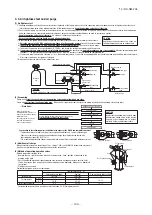
Plug the end of the pipe with tape, or other
material, and fill the pipe with nitrogen gas.
Only use nitrogen gas (N2)
Taping
<
N2
>
Nitrogen
Brazing
Brazing
Flatten
Adhesive tape
Station valve
Primary side
Secondary side
0.02MPa
Hand
Relief valve
Nitrogen
gas
Please note
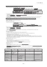
a) In connecting an outdoor unit, please use a pipe conforming to the pipe size specified for outdoor unit connection.
b) Choose a different-diameter pipe joint matching a main pipe size specified in the above section in installing pipes (= main pipes) on the outdoor unit side.
c) Always install branching pipe (for both gas and liquid) in such a manner that they form correct horizontal branch.
(4) Selection of an outdoor unit side branching pipe set
This branching pipe set will always become necessary when units are used in combination.
(When a unit is used as a standalone installation, it is not required)
For two units (for 450 – 670)
For three units (for 735 – 1000)
DOS-2A-3
DOS-3A-3
Outdoor unit
Branching pipe set
Please use C1220T-1/2H for
φ
19.05 or larger pipes.
Pipe sizes applicable to European installations are shown in parentheses.
Please use C1220T-1/2H for
φ
19.05 or larger pipes.
Pipe sizes applicable to European installations are shown in parentheses.
Please use C1220T-1/2H for
φ
19.05 or larger pipes.
(b) Main (Outdoor unit side branching pipe – Indoor unit side first branching pipe): Section B in Figure 1
If the longest distance (measured between the outdoor unit and the farthest indoor unit) is 90m or longer (actual length), please change the main pipe size
according to the table below.
(c) Indoor unit side first branching pipe – Indoor unit side branching pipe: Section C in Figure 1
Please choose from the table below an appropriate pipe size as determined by the total capacity of indoor units connected downstream, provided,
however, that the
pipe size for this section should not exceed the main size (Section B in Figure 1).
Gas pipe
φ
12.7
×
t 1.0
φ
15.88
×
t 1.0
φ
19.05
×
t 1.0 *1
φ
25.4
×
t 1.0
(
φ
28.58)
φ
28.58
×
t 1.0
φ
31.8
×
t 1.1
(φ
34.92
×
t 1.2
)
φ
38.1
×
t 1.35
(φ
34.92
×
t 1.2
)
Total capacity of indoor units
Less than 70
70 or more but less than 180
180 or more but less than 371
371 or more but less than 540
540 or more but less than 700
700 or more but less than 1100
1100 or more
Liquid pipe
φ
9.52
×
t 0.8
φ
12.7
×
t 0.8
φ
15.88
×
t 1.0
φ
19.05
×
t 1.0
(d) Indoor unit side branching pipe – Indoor unit: Section D in Figure 1
Indoor unit connection pipe size table
Capacity
15, 22, 28
36, 45, 56
71, 90, 112, 140, 160
224
280
Gas pipe
φ
9.52
×
t 0.8
φ
12.7
×
t 0.8
φ
15.88
×
t 1.0
φ
19.05
×
t 1.0
φ
22.22
×
t 1.0
Liquid pipe
φ
6.35
×
t 0.8
φ
9.52
×
t 0.8
Indoor unit
Use C1220T-1/2H material for
φ
19.05 or larger.
(e) Selection of pipe between outdoor branch pipes for 3-unit combination: Section E in Figure 1
Size of pipe between outdoor branch pipes varies depending on the capacity of outdoor unit which is connected to second branch pipe in the outdoors.
Select it from the following table.
Gas pipe
Liquid pipe
φ
28.58
×
t 1.0
φ
12.7
×
t 0.8
Size of pipe between branch pipes
Total capacity of outdoor units connected
to second branch pipe in the outdoors
500
560
615
670
Although this drawing illustrates an installation involving a 224 unit an installation involving a 280 or 335 unit should be arranged in the same manner as long as pipe
connection points and directions are concerned, except that the height of a unit is different.
Measurements in [ ] indicate those of a 280 or 335 unit.
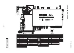
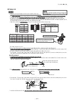
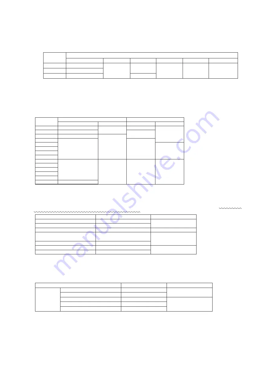
4-2. Pipe connection position and pipe direction
Total capacity downstream
Less than 180
180 or more but less than 371
371 or more but less than 540
540 or more
Branching pipe set
DIS-22-1G
DIS-180-1G
DIS-371-1G
DIS-540-3
Total capacity downstream
Less than 180
180 or more but less than 371
371 or more but less than 540
540 or more
Header set model type
HEAD4-22-1G
HEAD6-180-1G
HEAD8-371-2
HEAD8-540-3
Number of branches
4 branches at the most
6 branches at the most
8 branches at the most
8 branches at the most
(5) Selection of an indoor unit side branching pipe set
(a) Method of selecting a branching pipe set
●
As an appropriate branching pipe size varies with the connected capacity (total capacity connected
downstream), determine a size from the following table.
Please note
●
In connecting an indoor unit with the indoor unit side branching pipe set, please use a pipe
conforming to the pipe size specified for indoor unit connection.
●
Always install branching pipes (both gas and liquid pipe)
either horizontally or vertically
.
(b) Header Method
●
Depending on the number of units connected, connect plugged pipes (to be procured on the installer’s part) at a branching point (on the indoor unit connection side).
●
For the size of a plugged pipe, please refer to the documentation for a header set (optional part).
Please note
a) In connecting a header with an indoor unit, please use a pipe conforming to the pipe size specified for indoor unit connection.
b)
In installing a header, always arrange a gas-side header to branch horizontally and a liquid-side header to branch downward.
c) Indoor units 224 and 280 can not be connected to the header.
An oil equalizing pipe must be connected only when an outdoor unit is used in a
combined installation.
(When a unit is used as a standalone installation, do not connect it)
A: Opening for refrigerant gas pipe connection
B: Opening for refrigerant liquid pipe connection
C: Refrigerant pipe port (
φ
88 or
φ
100)
D: Power cable port (
φ
50)
E: Power cable port (oblong hole measuring 40x80)
F: Holes for hoisting slings
G: Opening for oil equalizing pipe connection
Explanatory marks
Gas pipe
Liquid pipe
Gas pipe
Liquid pipe
φ
19.05
×
t 1.0
φ
22.22
×
t 1.0
φ
25.4
(φ
22.22)
×
t 1.0
φ
28.58
×
t 1.0
φ
31.8
×
t 1.1
(φ
34.92
×
t 1.2
)
φ
38.1
×
t 1.35
(φ
34.92
×
t 1.2
)
φ
9.52
×
t 0.8
φ
12.7
×
t 0.8
φ
15.88
×
t 1.0
φ
38.1
×
t 1.35
(φ
34.92
×
t 1.2
)
φ
22.22
×
t 1.0
φ
25.4
(φ
22.22)
×
t 1.0
φ
31.8
×
t 1.1
(φ
28.58
×
t 1.0
)
φ
12.7
×
t 0.8
φ
15.88
×
t 1.0
φ
19.05
×
t 1.0
Main pipe size (normal)
Pipe size for an actual length of 90m or longer
Outdoor unit
224
280
335
450
500
560
615
670
735
800
850
900
950
1000
*1: When connecting indoor units of 280 at the downstream and the main gas pipe is of
φ
22.22 or larger, use the pipe of
φ
22.22x t1.0.
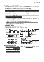
(1) Pipe connecting position and pipe outgoing direction
Please use C1220T-1/2H for
φ
19.05 or larger pipes.
※
1: Please connect the master and slave units with an oil equalization pipe, when they are used in a combined installation.
(It is not required, when a unit is used as a standalone installation)
When three outdoor units combination, please connect using a tee joint. (If contains in a branching pipe set for three units.)
(a) Outdoor unit – Outdoor unit side branching pipe: Section A in Figure 1
Please use a pipe conforming to the pipe size specified for outdoor unit connection.
Indoor unit connecting pipe size table
(3) Pipe size selection
Outdoor unit
224
280
335
φ
19.05
×t
1.0
φ
22.22
×t
1.0
φ
25.4 (
φ
22.22)
×t
1.0
φ
9.52
×t
0.8
φ
12.7
×t
0.8
Connection method
Blazed
Liquid pipe
Outdoor unit outlet pipe specifications
Connection method
Connection method
Oil equalizing pipe
Flare
Flare
φ
9.52
×t
0.8
※
1
Pipe sizes applicable to European installations are shown in parentheses.
Horizontal
Vertical
Floor surface
Floor surface
Floor surface
Floor surface
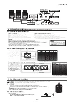
Incline branching pipes within
±15°against the floor surface.
±15°
Important
●
Please take care so that installed pipes may not touch components within a unit.
●
In laying pipes on the installation site, keep the operation valves shut all the time
.
●
Give
sufficient protections
(compressed and brazed or by an adhesive tape)
to pipe ends so that any water or foreign matters may not enter the pipes
.
●
In bending a pipe, bend it
to the largest possible radius (at least four times the pipe diameter)
. Do not bend a pipe repeatedly to correct its form.
●
An outdoor unit’s liquid pipe and liquid refrigerant piping are to be flare connected. Flare a pipe after engaging a flare nut onto it. A flare size for R410A is
different from that for conventional R407C. Although we recommend the use of flaring tools developed specifically for R410A, conventional flaring tools can also
be used by adjusting the measurement of protrusion B with a protrusion control gauge.
●
Tighten a flare joint securely
with two spanners
. Observe flare nut tightening torque specified in the table below.
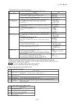
(2) Piping work
Flared pipe end: A (mm)
Copper pipe protrusion for flaring: B (mm)
φ
6.35
φ
9.52
φ
12.7
φ
15.88
Copper
pipe outer
diameter
0
-0.4
A
9.1
13.2
16.6
19.7
φ
6.35
φ
9.52
φ
12.7
φ
15.88
Copper
pipe outer
diameter
In the case of a rigid (clutch) type
With an R410A tool
With a conventional tool
0
-
0.5
0.7
-
1.3
●
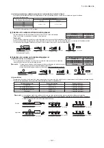
A pipe can be laid through the front, right, bottom or rear of a unit as illustrated on the above drawings.
●
In laying pipes on the installation site, cut off the casing’s half blank (
φ
88 or
φ
100) that covers a hole for pipe penetration with nippers.
●
When there is a danger that a small animal enters from the pipe port, cover the port with appropriate blocking materials (to be arranged on the user’s part).
●
Use an elbow (to be arranged on the user’s part) to connect control valves to the piping.
●
In anchoring piping on the installation site, give 1.5m or a longer distance between an outdoor unit and an anchoring point where the piping is secured as
illustrated below. (A failure to observe this instruction may result in a pipe fracture depending on a method of isolating vibrations employed.)
●
The pipe should be anchored every 1.5m or less to isolate the vibration.
Over 1.5m
Pipe fastening position
CAUTION
If you tighten it without using double spanners, you may deform
the operation valve, which can cause an inflow of nitrogen gas
into the outdoor unit.
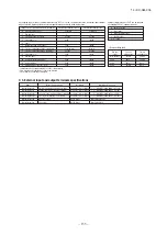
Tightening torque (N
・
m)
Operation valve size
(mm)
Tightening angle
(° )
Tightening torque
(N
・
m)
Recommended length of tool handle
(mm)
φ
6.35 (1/4")
14-18
45-60
150
φ
9.52 (3/8")
34-42
30-45
200
φ
12.7 (1/2")
49-61
30-45
250
φ
15.88 (5/8")
68-82
15-20
300
φ
19.05 (3/4")
100-120
15-20
450
Use a torque wrench. If a torque wrench is not available,
fasten the flare nut manually first and then tighten it
further, using the left table as a guide.
Do not hold the valve cap area with a spanner.
●
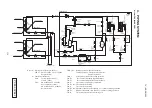
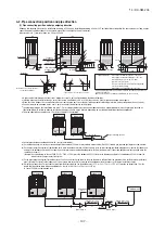
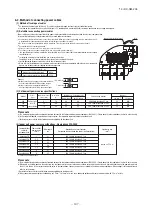
Connect pipes between combined units, with care for the followings.
(a) On combination units, it must be secured a straight pipe section of 500 mm or more before a branch pipe (Type DOS) for both gas pipe and liquid pipe as shown below.
(b) On the pipe connection system of combination units, place the outdoor unit of which the capacity is the smallest among combined outdoor units, closer to the indoor unit,
and place the outdoor unit of which the capacity is the largest among combined outdoor units, far from the indoor unit. (Connecting positions are not specified when the
capacities are same.)
(Example) As shown below, in case of P800 (P224 + P280 + P280), place the outdoor unit P224 closer to the indoor unit and place the outdoor unit P280 far from the
indoor unit in the pipe connection system.
(c) On the pipe connection system for combination of 3 units, use a branch pipe of which the pipe diameter is different after the pipe branching, for the branch pipe (branch
pipe 1) located the closest to the indoor unit. It is necessary also to connect a thin pipe to the outdoor unit and to connect a thick pipe to next branch pipe.
(d) It must be no longer than 5m the length of pipe from the branching pipe 1 to the outdoor unit. (L
1
5 m, L
2
+L
4
5 m, L
3
+L
4
5 m) It must be no longer than 10 m the
length of oil equalizing pipes between outdoor units. (La+Lb 10 m, Lb+Lc 10 m, La+Lc 10 m)
In case of P800 three combination unit:
Branch pipe section
500 mm or more
(Branch pipe 2)
L
3
L
4
L
1
La
L
2
Lb
Lc
(Branch pipe 1)
Thin pipe
Thick pipe
P280
P224
P280
Branch pipe section
500 mm or more
To indoor unit
<
=
<
=
<
=
<
=
<
=
<
=
Oil equalizing
pipes
●
Do not apply any oil on a flare joint.
●
Pipes are to be blazed to connect an outdoor unit’s gas pipe with refrigerant piping or refrigerant piping with a branching pipe set.
●
Blazing must be performed under a nitrogen gas flow
. Without nitrogen gas, a large quantity of foreign matters (oxidized film) are created, causing a critical
failure from capillary tube or expansion valve clogging.
●
Brazing of the operation valve and the pipes should be performed while cooling the valve body with a wet towel.
●
Perform flushing. To flush the piping, charge nitrogen gas at about 0.02MPa with a pipe end closed with a hand. When pressure inside builds up to a sufficient
level, remove the hand to flush. (in flushing a pipe, close the other end of the pipe with a plug).
Operation procedure
①
In laying pipes on the installation site, keep the operation valves shut all the time
.
②
Blazing must be performed under a nitrogen gas flow
. Without nitrogen gas, a large quantity of foreign matters (oxidized film) are created, causing a critical
failure from capillary tube or expansion valve clogging.
③
Give
sufficient protections
(compressed and brazed or with an adhesive tape)
so that water or foreign matters may not enter the piping
.
④
Perform flushing. To flush the piping, charge nitrogen gas at about 0.02MPa with a pipe end closed with a hand. When pressure inside builds up to a sufficient
level, remove the hand to flush. (in flushing a pipe, close the other end of the pipe with a plug).
⑤
In brazing an operation valve and a pipe,
braze them with the valve main body cooled with a wet towel or the like
.
Gas pipe


