-
158
-
'14 • KX-SM-204
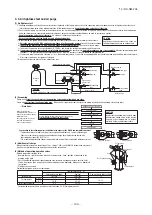
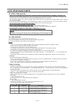
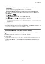
(1) To avoid mixing of different types of oil, use separate tools for each type of refrigerant.
(2) To avoid moisture from being absorbed by the refrigerant oil, the time for when the refrigerant circuit is open should be kept as short as possible. (Within 10 min. is
ideal.)
(3) For other piping work, airtighteness testing , vacuuming, and refrigerant charging, refer to section 3, Refrigerant piping.
(4) Diagnostic Inspection Procedures
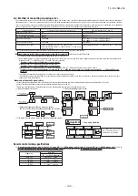
For the meanings of failure diagnosis messages, please refer to the nameplate provided on the unit (on the back of the control lid)
(5) 7-segment LED indication
Data are indicated when so chosen with the indication selector switch. For the details of indication, please refer to the cable name plate attached on the unit. (On the
face of the control lid)
(6) Internal wiring
After maintenance, all wiring, wiring ties and the like, should be returned to their original state and wiring route, and the necessary clearance from all metal parts
should be secured.
(2) Method of starting a test run for a cooling operation from an outdoor unit: please operate a remote control unit according to the following steps.
(a) Start of a cooling test run
○
Operate the unit by pressing the START/STOP button.
○
Select the “COOLING” mode with the MODE button.
○
Press the TEST RUN button for 3 seconds or longer.
The screen display will be switched from “Select with ITEM ”
→
“Determine with SET ”
→
“Cooling test run
▼
.”
○
When the SET button is pressed while “Cooling test run
▼
” is displayed, a cooling test run will start. The screen display will be switched to “COOLING TEST RUN.”
(b) Termination of a cooling test run
○
When the START/STOP button or the “TEMP SET ” button is pressed, a cooling test run will be terminated.
Notes : for engineers undertaking piping or electrical installation work
When a test run is completed, please make sure again that the electrical component box cover and the main body panel have been attached before you turn
the unit over to the customer.
9. CAUTIONS FOR SERVICING (for R410A and compatible machines)
(1) Test run from an outdoor unit.
Whether external inputs are set to ON or OFF, you can start a test run by using the SW5-1 and SW5-2 switches provided on the outdoor unit board.
Select the test run mode first.
Please set SW5-2 to ON for a cooling test run or OFF for a heating test run. (It is set to OFF at the factory for shipment)
Turning SW5-1 from OFF to ON next will cause all connected indoor units to start.
When a test run is completed, please set SW5-1 to OFF.
Note: During a test run, an indoor unit cannot be operated from the remote control unit (to change settings). (“Under centralized control” is indicated)
8-4. Test operation
8-5. TRANSFER
○
Use the instruction manual that came with the outdoor unit to explain the operation method to the customer.
Please ask the customer to keep this installation manual together with the operation manual of his indoor units.
○
Instruct the customer that the power should not be turned off even if the unit is not to be used for a long time. This will enable operation of the air conditioner any time.
(Since the compressor bottom is warmed by the crank case heater, seasonal compressor trouble can be prevented.)
▲
▼
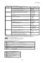
Error display on 7-segment indicator after ending the check operation
Code indicato
Data indicator
Display contents
Check following points
CHL
CHU
CHJ
CHE
Operation valve is closed.
(Refrigerant circuit is shut off
partially.)
・
Isn’t the operation valve of outdoor unit left open?
・
Is the low pressure sensor normal? (Detected pressure can be seen on
the 7-segment indicator.)
・
Is the connector of indoor unit expansion valve coil connected?
・
Isn’t the indoor unit expansion valve coil disconnected from the
expansion valve body?
・
Is the indoor unit heat exchanger sensor normal? (Check if the sensor is
disconnected.)
Mismatch between
refrigerant pipes and signal
cables. Refrigerant is not
circulated to the indoor unit of
which No. is displayed.
・
Are the refrigerant pipes and signal cables connected properly between
the indoor and outdoor units?
・
Is the connector of indoor unit expansion valve coil connected?
・
Isn’t the indoor unit expansion valve coil disconnected from the
expansion valve body?
・
Is the indoor unit heat exchanger sensor normal? (Check if the sensor is
disconnected.)
Expansion valve on the indoor
unit of which No. is displayed
is not operating properly.
・
Is the connector of indoor unit expansion valve coil connected?
・
Isn’t the indoor unit expansion valve coil disconnected from the
expansion valve body?
・
Is the indoor unit heat exchanger sensor normal? (Check if the sensor is
disconnected.)
Abnormal ending of check
operation.
・
Isn’t any error displayed (E??) on the indoor unit or outdoor unit?
・
Are signal cables connected without play?
・
Hasn’t the SW setting been changed during the check operation?
※
When any error is detected, errors other than those listed above may be displayed. In such occasion, refer to the separate technical data.
Abnormal indoor unit No.
Abnormal indoor unit No.
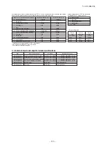
(1) Guideline of accuracy
8-3. Refrigerant quantity check
Refrigerant quantity check tells you whether the refrigerant quantity is excessive (over) or insufficient (low).
(Even if the check operation is not practiced, the test run and normal operation can be performed.)
For further details regarding the check operation refer to the technical data.
It must be noted that, during the check operation, the outdoor units and the indoor units are operated automatically.
Guidelines of judgment on the refrigerant quantity are as shown below.
It should be noted that the result of judgment could vary depending on the conditions of judgment.
(2) Confirmation before implementing the refrigerant quantity check
Confirm on all of the followings before starting the refrigerant quantity check.
・
Confirm that it has been completed all works up to “8-1 Before starting operation”.
・
Check operation cannot be done when the total capacity of connected indoor units is less than 80% of the outdoor unit capacity.
・
Check operation cannot be done when the system communication method is that of previous SL.
・
Check operation cannot be done when the system is stopped by an error.
・
Practice the check operation within applicable operation temperature range (Outdoor temperature: 10 - 43˚C, room temperature: 15 - 32˚C). Check operation
will not start out of these ranges.
・
Start the check operation only at 5 minutes after stopping all indoor units.
(3) Method of refrigerant quantity check operation
(a) Starting the refrigerant quantity check operation
・
Confirm that all of the following switches are turned OFF; SW3-2 (Auto backup operation), SW3-6 (Pipe wash mode), SW3-7 (Forced cooling/heating mode),
SW5-1 (Test run), SW5-2 (Test run cooling setting), SW5-3 (Pump-down operation) and SW5-6, 7, 8 (Capacity measurement mode). (In case of combination,
on both master/slave units)
・
At the next, turn the SW3-4 (Refrigerant quantity check operation) OFF
→
ON (only on master unit in case of combination) so that the check operation will start.
・
It takes 60 ~ 75 minutes normally from the start to the end of check operation.
(b) End of refrigerant quantity check operation and result display
・
When the check operation is over, the system stops automatically, and the result is displayed on the 7-segment indicator. (Only on master unit in case of
combination)
< Normal ending >
・
7-segment indicator shows “Co End”.
・
Return the SW3-4 to OFF. 7-segment indicator returns to normal display.
< Abnormal ending >
・
7-segment indicator shows an error alarm.
・
Repair the faulty section referring to the guidance, and return the SW3-4 to OFF.
・
At the next, repeat the check operation from the Step (2) above.
・
Practice the refrigerant quantity check operation only after charging the measured quantity of additional
refrigerant.
・
It is necessary to add or reduce the refrigerant depending on the result of refrigerant quantity check. Even when
it has been judged that proper quantity of refrigerant is retained, the result could become inadequate if the
operating conditions are changed.
・
It should be noted, therefore, that a result under particular conditions cannot cover all operating conditions.
Important
Refrigerant quantity over
+10 kg (Single machine)
+20 kg (Combination machine)
Low refrigerant quantity
20% of the additional refrigerant quantity for piping (P)
(4) After the refrigerant quantity check operation
Following codes may be displayed at the end of check operation, other than “Co End”.
Check and take action according to the contents of remedy. And then, repeat the check operation.
Display on 7-segment indicator after the check operation (Displayed on master unit only in case of combination.)
Code indicator
Data indicator
Meaning
Remedy
Co
Hi
Refrigerant quantity over
①
Too much refrigerant is charged. Reduce the quantity.
< Guidelines of reduction >
・
Single machine:10 kg
・
Combination machine:20 kg
Make sure to recover the refrigerant from the check joint of liquid pipe operation valve
using the refrigerant recovery device.
Co
Lo
Low refrigerant quantity
①
Refrigerant quantity is insufficient. Recharge the refrigerant.
< Guideline of recharge>
・
20% of the additional refrigerant quantity for piping* (Upper limit: 5 kg)
Recharge the refrigerant in the liquid state from the check joint of low pressure line.
Make sure to measure the quantity before recharging.
Co
H_L
Couldn’t judge.
It cannot judge (a state that it cannot judge properly).
State of refrigerant might have been unstable during the check operation due to
influence of wind, temperature change, etc.
①
Check the expansion valve of indoor unit (disconnected coil, disconnected connector
or faulty expansion valve).
②
Implement at a later date by changing the conditions.
Co
---
Judgment was interrupted.
Check the following points.
①
Haven’t you changed the setting of dip switches after the start? Return them to
original setting.
②
Is any error code (E??) displayed? If Yes, refer to the troubleshooting section in the
technical data.
Co
HE
Starting conditions are not met.
Starting conditions are not met so that it cannot start the check operation.
Refer to “(2) Confirmation before implementing the refrigerant quantity check”.
※
“Additional refrigerant quantity for piping” means the value of “Additional refrigerant quantity for piping (P)+(I)” in the Section 4-4 Additional
refrigerant charge.
Other errors than above may also be displayed if errors are detected. In such occasion, inspect by referring to the separate technical data.
(1)
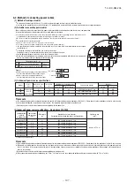
Make sure that a measurement between the power source terminal block and ground, when measured with a 500V megger, is greater than 1 M
Ω
.
When the unit is left for a long time with power OFF or just after the installation, there is possibility that the refrigerant is accumulated in the compressor and the
insulation resistance between the contact terminals for power source and grounding decreases to 1M
Ω
or around.
When the insulation resistance is 1M
Ω
or more, the insulation resistance will rise with crank case heater power ON for 6 hours or more because the refrigerant in
the compressor is evaporated.
(2) Please check the resistance of the signaling wire terminal block before power is turned on. If a resistance measurement is 100
Ω
or less, it suggests a possibility
that power cables are connected to the signaling wire terminal block. (Please refer to 6-3. Standard resistance value.)
(3)
Be sure to turn on the crank case heater 6 hours before operation
.
(4)
Make sure that the bottom of the compressor casing is warm
. (higher than outdoor tempe5°C)
(5) Be sure to fully open the operation valves (liquid,gas and Equalizen oil piping (for a combined installation only)) for the outdoor unit.
Operating the outdoor unit with the valves closed may damage the compressor.
(6)
Check that the power to all indoor units has been turned on. If not, water leakage may occur
.
It is recommended to practice the check operation in precedent to the test run.
[Even if the check operation is not practiced, the test run and normal operations can be performed.]
For further details regarding the check operation refer to the technical data.
・
Practice the check operation after completing the address setting for the indoor and outdoor units and also after charging the refrigerant.
・
To assure accurate checking, proper amount of refrigerant must be retained.
・
Check operation cannot be done when the system is stopped by an error.
・
Check operation cannot be done when the total capacity of connected indoor units is less than 80% of the outdoor unit capacity.
・
Check operation cannot be done when the system communication method is previous SL.
・
Don’t perform the check operation simultaneously on more than one refrigerant line. Accurate checking cannot be obtained.
・
Practice the check operation within the operation temperature ranges (Outdoor temperature: 0 – 43°C, room temperature: 10 – 32°C). Check operation will not
start out of these ranges.
・
Outdoor air processing unit cannot be checked. (It is possible to check indoor units other than the outdoor air processing unit of the same refrigerant line.)
Check operation allows proving the following points.
・
Whether or not the operation valve is left open (Operation valve open/close check). (In case of combination, however, all operation valves need to be closed on
master and slave units to obtain accurate judgment.)
・
Whether or not the refrigerant pipes and signal cables are connected properly between indoor and outdoor units. (Mismatch check)
・
Whether or not the indoor expansion valve operates properly. (Expansion valve failure check)
CAUTION
Please make sure that the operation valves (gas, liquid, oil equalizing pipe (for a combined installation only)) are full
open before a test run. Conducing a test run with any of them in a closed position can result in a compressor failure.
8. TEST OPERATION AND TRANSFER
8-1. Before starting operation
8-2. Check operation
Important
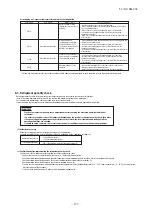
(1)
Check items
Display on 7-segent indicator during check operation
(a) Starting the check operation
・
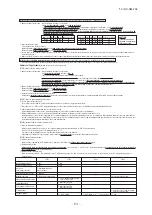
Confirm that all of the following switches are turned OFF: SW3-2 (Auto backup operation), SW3-6 (Pipe wash mode), SW3-7 (Forced cooling/heating mode),
SW5-1 (Test run), SW5-2 (Test run cooling setting), SW5-3 (Pump-down operation) and SW5-6, -7, -8 (Capacity measurement mode). (In case of combination, on
both main and slave units)
・
At the next, turn the SW3-5 (Check operation) OFF
→
ON (only on master unit in case of combination) so that the check operation will start.
・
It takes 15 – 30 minutes normally (max. 80 min) from the start to the end of check operation.
(b) End the check operation and the result display
・
When the check operation is over, the system stops automatically. The 7-segment indicator shows the result (only on master unit in case of combination).
<Normal ending>
・
7-segment indicator shows “CHO End”.
・
Return the SW3-5 to OFF. The 7-segment indicator returns to normal display.
<Abnormal ending>
・
7-segment indicator shows an error alarm.
・
Referring to the section [Inspect here], repair the faulty section and return the SW3-5 to OFF.
・
At the next, repeat the check operation from the Step (2) above.
(2)
Method of check operation
Code indicator
Data indicator
Display contents
Max. remaining time
Max. remaining time
H1
H2
CHO
End
Check operation preparation on. Indicates max. remaining time (min).
(In case of combination, indicated on master unit only.)
Check operation on. Indicates max. remaining time (min).
(In case of combination, indicated on master unit only.)
Normal ending of check operation.
(In case of combination, indicated on master unit only.)

