'19 • PAC-SM-309
-
187
-
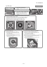
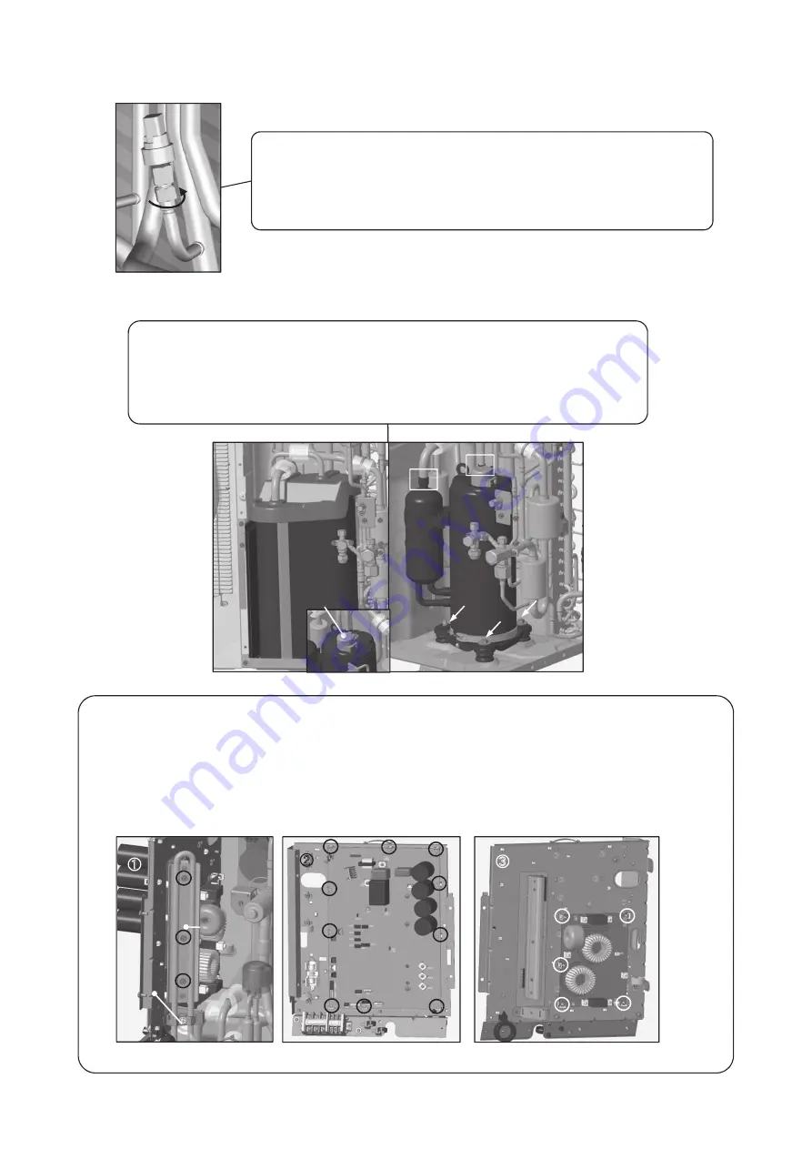
7. To remove the low pressure sensor (PSL)
(1) Remove the service panel.(See No.1)
(2) Disconnect the PSL connector(CNPSL) on PCB in control box.
(3) Turn PSL unticlockwise and remove it.
(Double spanners are needed.)
* Be sure to collect a refrigerant before remove the low pressure sensor.
8. To remove the compressor (CM)
(1) Remove the service panel.(See No.1)
(2) Remove the insulation which covers compressor. (Strings (a)
~
(b) should be loosen.)
(3) Remove the terminal cover fixing bolt and remove it, and disconnect the power wiring.
(4) Remove welded part of compressor by welding. (
□
mark)
(5) Remove 3 compressor fixing nuts(
←
mark) using spaner or adjustable wrench.
9. To remove the printed circuit board (PCB)
(1) Remove the service panel and rear panel, top panel.
(2) Remove 3 cupper plate fixing screws.(
○
mark, Pic.
①
)
(3) Pull off all the inserted connectors of control PCB.(Pic.
②
)
(4) Take off 10 control PCB fixing locking supports and remove it.(
○
mark, Pic.
②
)
(5) Pull off all the inserted connectors of NF PCB.(Pic.
③
)
(6) Take off 5 NF PCB fixing locking supports and remove it.(
○
mark, Pic.
③
)
PROCEDURE & PICTURES
PCA012D089A
(a)
(b
Terminal cover
②
Control PCB
①
Control
Cupper
③
NF PCB
Front of controller
Rear of controller
2
Summary of Contents for FDC100VNA-W
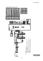
Page 70: ... 19 PAC SM 309 69 LED2 Red LED1 Green ...
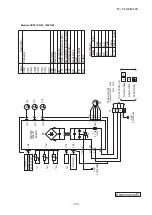
Page 72: ... 19 PAC SM 309 71 ...
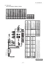
Page 74: ... 19 PAC SM 309 73 LED2 Red LED1 Green ...
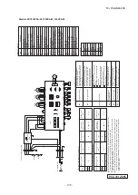
Page 76: ... 19 PAC SM 309 75 ...
Page 183: ... 19 PAC SM 309 182 1 e SRK series PHA012D402 ...
Page 184: ... 19 PAC SM 309 183 Screw ...
Page 185: ... 19 PAC SM 309 184 3 PHA012D402 ...
Page 186: ... 19 PAC SM 309 185 4 PHA012D402 ...


