'19 • PAC-SM-309
-
22
-
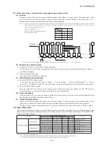
(17) Plural unit control – Control of 16 units group by one remote control
(a) Function
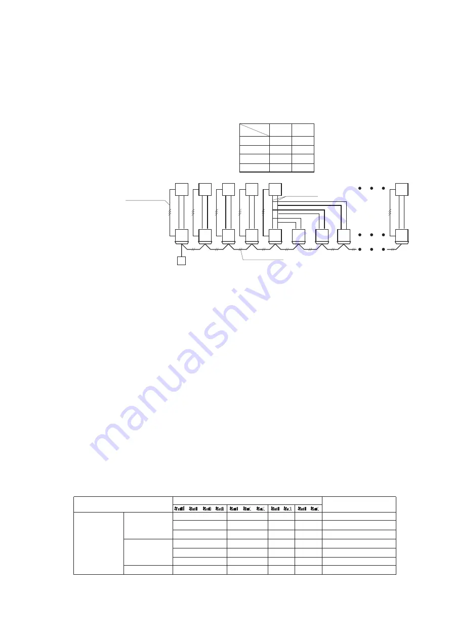
One remote control can control a group of multiple number of unit (Max. 16 indoor units). “Operation mode” which
is set by the remote control can operate or stop all units in the group one after another in the order of unit. No.
(1)
.
Thermostat and protective function of each unit function independently.
Note (1) Unit No. is set by SW2 on the indoor unit control PCB. Unit No. setting by SW2 is necessary for the indoor unit only. In cases of the twin,
triple and double twin specification, it is necessary set for the master and the slave units. This can be selected by SW5. (All are set for the
master unit at the shipping from factory.)
(2) Unit No. may be set at random unless duplicated, it should be better to set orderly like 0, 1, 2…, F to avoid mistake.
(b) Display to the remote control
(i) Central or each remote control basis, heating preparation
The smallest unit No. among the operating units in the remote mode (or the center mode unless the remote mode is
available) is displayed.
(ii) Inspection display, filter sign
Any of unit that starts initially is displayed.
(c) Confirmation of connected units
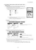
(i) In case of RC-EX3A remote control
If you touch the buttons in the order of “Menu” → “Service setting” → “Service & Maintenance” → “Service
password” → “IU address”
on the TOP screen of remote control, the indoor units which are connected are displayed.
(ii) In case of RC-E5 remote control
Pressing “AIR CON No.” button on the remote control displays the indoor unit address. If “▲” “▼” button is
pressed at the next, it is displayed orderly starting from the unit of smallest No.
(d) In case of anomaly
If any anomaly occurs on a unit in a group (a protective function operates), that unit stops with the anomalous stop
but any other normal units continue to run as they are.
(e)
Signal wiring procedure
Signal wiring between indoor and outdoor units should be made on each unit same as the normal wiring. For the
group control, connect the remote control wiring to each indoor unit via terminal block for the remote control.
Connect the remote control wiring separately from the power source cable or wires of other electric devices (AC220V or higher).
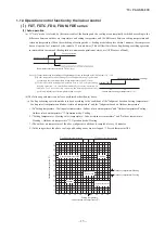
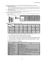
(18) High ceiling control
When sufficient air flow rate cannot be obtained from the indoor unit which is installed at a room with high ceiling, the air
flow rate can be increased by changing the fan tap. To change the fan tap, use the indoor unit function “FAN SPEED SET”
on the wired remote control.
-
-
-
-
-
-
-
P-Hi1 - Hi
P-Hi1 - Me
P-Hi1 - Hi - Me
STANDARD
HIGH SPEED1
FAN SPEED SET
Hi - Lo
Hi - Me Only FDE
Only FDT
Only FDT, FDE
Hi - Me - Lo
Hi - Lo
Hi - Me
Hi - Me - Lo
P-Hi2 - P-Hi1 - Hi - Me
P-Hi1 - Hi
P-Hi1 - Me
P-Hi1 - Hi - Me
Except FDT, FDE
P-Hi1 - P-Hi1 - Hi - Me
P-Hi2 - Hi - Me - Lo
Hi - Lo
Hi - Me Only FDT
Hi - Me - Lo
P-Hi2 - Hi - Me - ULo
Hi - Lo
Hi - Me Except FDT, FDE
Hi - Me - Lo
P-Hi1 - Hi - Me - Lo
Indoor unit air flow setting
Series
Fan tap
HIGH SPEED2
P-Hi2 - Hi - Me - Lo
Only FDE
Hi - Lo
Hi - Me
Hi - Me - Lo
P-Hi1 - Hi - Me - Lo
Notes (1) Factory default is STANDARD.
(2) At the hot-start and heating thermostat OFF, or other, the indoor fan is operated at the low speed tap of each setting.
(3) This function is not able to be set with wireless remote control or simple remote control (RCH-E3).
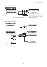
SW2: For setting of 0 – 9, A – F
SW5: For setting of master and slave units
(See table shown at right.)
Remote control
Indoor unit
Outdoor unit
Signal wiring
between outdoor unit
and indoor units
(Master unit)
(Slave unit a)
(Slave unit b)
Remote control wiring
R
0
1
2
3
F
4
4
4
(Slave unit c)
4
Refrigerant piping
Master unit
OFF
OFF
OFF
ON
SW5-1
SW5-2
ON
OFF
ON
ON
Slave unit a
Slave unit b
Slave unit c
Switch
Unit
SW5 setting
Summary of Contents for FDC100VNA-W
Page 70: ... 19 PAC SM 309 69 LED2 Red LED1 Green ...
Page 72: ... 19 PAC SM 309 71 ...
Page 74: ... 19 PAC SM 309 73 LED2 Red LED1 Green ...
Page 76: ... 19 PAC SM 309 75 ...
Page 183: ... 19 PAC SM 309 182 1 e SRK series PHA012D402 ...
Page 184: ... 19 PAC SM 309 183 Screw ...
Page 185: ... 19 PAC SM 309 184 3 PHA012D402 ...
Page 186: ... 19 PAC SM 309 185 4 PHA012D402 ...

