–
284
–
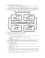
(3) Operation control function by the remote controller
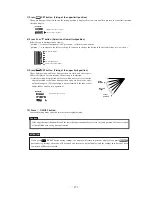
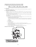
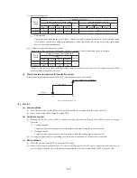
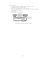
(1) Switching sequence of the operation mode switches of remote controller
Dehumidifying
Cooling
Fan
Heating
Auto
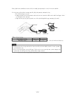
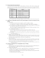
(2) [CPU reset]
When the “CHECK” and “GRILL” buttons on the remote controller are pressed at the same time, this function is activated. This
function is same as power supply reset.
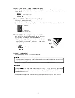
(3) [Power failure compensation function]
• This function becomes effective when “POWER FAILURE COMPENSATION SET” is valid by setting the remote controller
functions.
• The remote controller's status is always stored in memory, and after recovery of power, operation is resumed according to
the memory contents. However the auto swing stop position and timer mode are cancelled, but the weekly timer setting is
restored with the holiday setting through all weekdays.
By resetting the clock and cancelling the holiday setting for each weekday after recovery of power, weekly timer setting
becomes effective.
• Contents stored in memory for power failure compenstion are as follows.
Note (1) Item
➅➆
and
➇
are stored in memory regardless of whether the power failure compensation setting is valid or invalid, and silent mode setting is
cancelled regardless of whether the power failure compensation setting is valid or invalid.
➀
Running or Stopping status just before power failure
If it had been operating under OFF timer mode or simple timer mode, memorzed status is as stopping (At the
recovery of power, the timer mode is cancelled but weekly timer setting is changed to the holiday setting through all
weekdays
➁
Operation mode
➂
Fan speed mode
➃
Room temperature setting
➄
Louver auto swing/stop
However, the stop position (position 4) is cancelled and is becomes the level position (position 1).
➅
“Remote control function items”, set with the remote controller function setting (“Indoor unit function items” are
stored in the inoor unit's memory.)
➆
Upper limit value and lower limit value set by temperature setting control.
➇
Clock timer setting and weekly timer setting (Other timer settings are not sotred in memory).
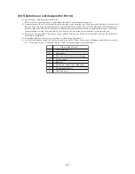
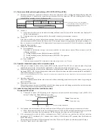
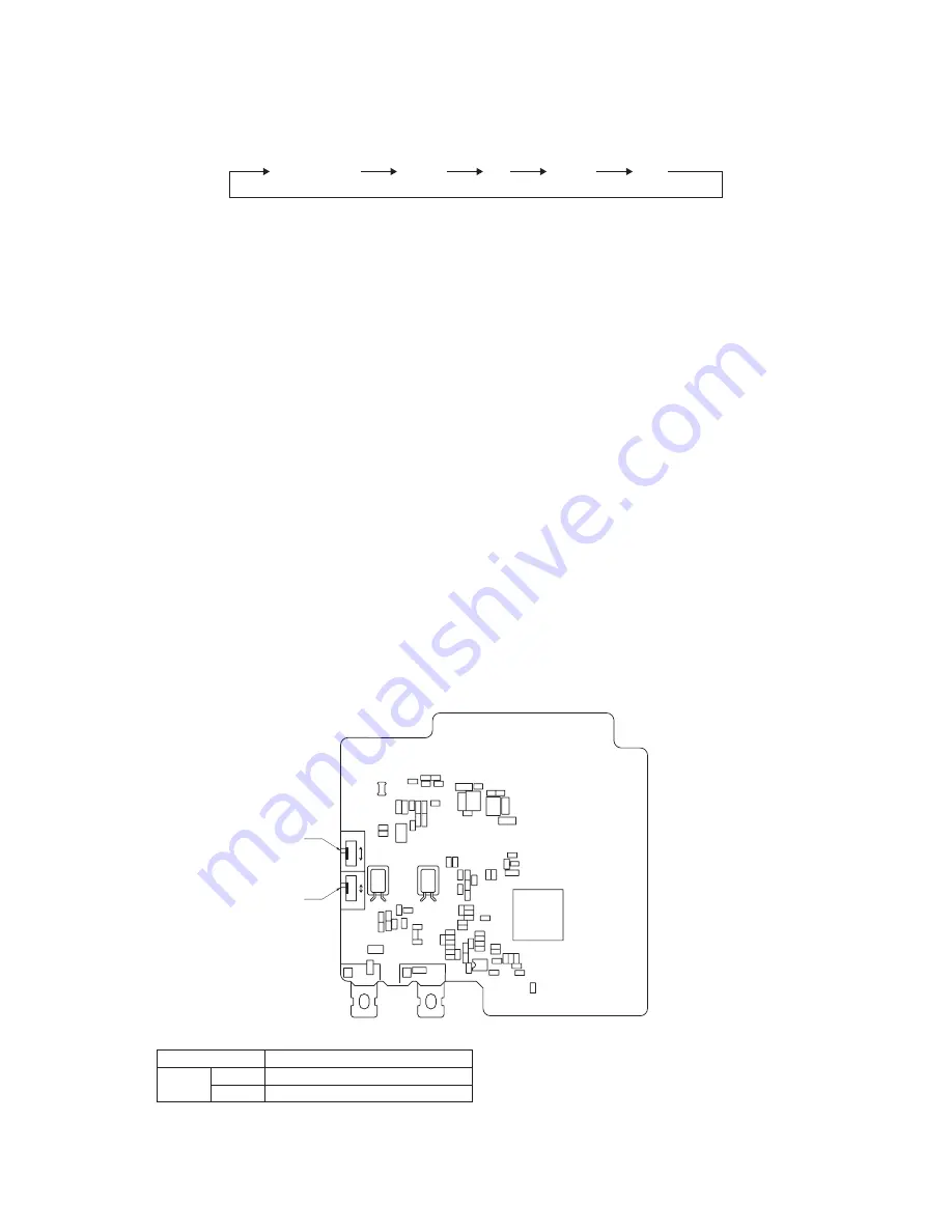
[Parts layout on remote controller PCB]
X
Y
SW2
SW1
A
B
M
S
親
子
SW1
SW2
Control selector switch (SW1)
Switch
Function
SW1
M
Master remote controller
S
Slave remote controller
Note (1) SW2 is not normally used, so do not change the selection.
Summary of Contents for FDC112KXEN6
Page 116: ... 112 4 Sensible heat capacity ...
Page 117: ... 113 ...
Page 118: ... 114 ...
Page 119: ... 115 ...
Page 120: ... 116 ...
Page 121: ... 117 ...
Page 122: ... 118 ...
Page 123: ... 119 ...
Page 124: ... 120 ...
Page 125: ... 121 ...
Page 126: ... 122 ...
Page 127: ... 123 ...
Page 128: ... 124 ...
Page 129: ... 125 ...
Page 130: ... 126 ...
Page 131: ... 127 ...
Page 132: ... 128 ...
Page 133: ... 129 ...
Page 134: ... 130 ...
Page 135: ... 131 ...
Page 136: ... 132 ...
Page 137: ... 133 ...
Page 138: ... 134 ...
Page 139: ... 135 ...
Page 140: ... 136 ...
Page 141: ... 137 ...
Page 142: ... 138 ...
Page 143: ... 139 ...
Page 144: ... 140 ...
Page 145: ... 141 ...
Page 146: ... 142 ...
Page 147: ... 143 ...
Page 148: ... 144 ...
Page 149: ... 145 ...
Page 150: ... 146 ...
Page 151: ... 147 ...
Page 152: ... 148 ...
Page 153: ... 149 ...
Page 154: ... 150 ...
Page 155: ... 151 ...
Page 156: ... 152 ...
Page 157: ... 153 ...
Page 158: ... 154 ...
Page 159: ... 155 ...
Page 160: ... 156 ...
Page 161: ... 157 ...
Page 162: ... 158 ...
Page 163: ... 159 ...
Page 164: ... 160 ...
Page 165: ... 161 ...
Page 166: ... 162 ...
Page 167: ... 163 ...
Page 168: ... 164 ...
Page 169: ... 165 ...
Page 170: ... 166 ...
Page 171: ... 167 ...
Page 172: ... 168 ...
Page 173: ... 169 ...


