–
295
–
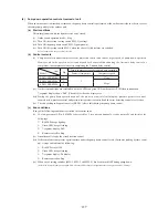
(8) Pump down operation control at removal of unit
When an outdoor unit is discarded or removed, the pump down control is performed at the outdoor unit side in order to recover
the refrigerant quickly to the outdoor unit.
(a) Start conditions
This is implemented with the liquid service valve closed.
(i) Outdoor unit operation mode – Stop
(ii) Turn ON the test run cooling switch SW5-2 (cooling).
(iii) Turn ON the pump down switch SW5-3 (pump down).
(iv) Turn ON the test run switch SW5-1 when the above (i)-(iii) statuses are satisfied.
Note (1) Input before the power ON is invalid.
(b) Control contents
(i) Compressor starts under compressor start protection control and runs at target speed of pump down operation.
However, when the operation start conditions have been established during the 3-minute delay control of
compressor, the compressor starts after completing the 3-minute delay control.
Item
Model
Hp
Target compressor speed at pump down operation
Number of compressors
Compressor speed
FDC112KXEN/S6
4
1
37rps
FDC140KXEN/S6
5
45rps
FDC155KXEN/S6
6
(ii) As the start conditions are established, both red LED and green LED on the outdoor PCB flash continuously.
7-segment display shows “PdS” (Channel 0) at the code display area.
(iii) During the pump down operation control, the protective controls (excluing low pressure protective control,
anomalous low pressure control and pressure ratio protection control) and the error detection control are effective.
(iv) The sub-cooling coil expansion valve (EEVSC) closes fully during the pump down control.
(c) End conditions
If any of the following conditions is satisfied, this control ends.
(i) If a low pressure (LP) ≤ 0.01MPa is detected for 5 seconds continuously, it ends normally and initiates the
followings.
➀
Red LED: keeps lighting
➁
Green LED: keeps flashing
➂
7-segment display: PdE
➃
Remote controller: Stop
(ii) Anomalous all stop by the error detection control
(iii) If the cumulative compressor operation time under the pump down control totals 15 minutes (ending by time count
up), it stops and initiates the following.
➀
Red LED: stays OFF
➁
Green LED: keeps flashing
➂
7-segment display: No display
➃
Remote controller: Stop
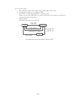
(iv) When any of setting switches (SW5-1, SW5-2 and SW5-3) has been turned OFF during pump down.
(Note) Even if only the pump down switch SW5-3 is turned OFF, it does not recognized as the cooling test run mode , but stops
Summary of Contents for FDC112KXEN6
Page 116: ... 112 4 Sensible heat capacity ...
Page 117: ... 113 ...
Page 118: ... 114 ...
Page 119: ... 115 ...
Page 120: ... 116 ...
Page 121: ... 117 ...
Page 122: ... 118 ...
Page 123: ... 119 ...
Page 124: ... 120 ...
Page 125: ... 121 ...
Page 126: ... 122 ...
Page 127: ... 123 ...
Page 128: ... 124 ...
Page 129: ... 125 ...
Page 130: ... 126 ...
Page 131: ... 127 ...
Page 132: ... 128 ...
Page 133: ... 129 ...
Page 134: ... 130 ...
Page 135: ... 131 ...
Page 136: ... 132 ...
Page 137: ... 133 ...
Page 138: ... 134 ...
Page 139: ... 135 ...
Page 140: ... 136 ...
Page 141: ... 137 ...
Page 142: ... 138 ...
Page 143: ... 139 ...
Page 144: ... 140 ...
Page 145: ... 141 ...
Page 146: ... 142 ...
Page 147: ... 143 ...
Page 148: ... 144 ...
Page 149: ... 145 ...
Page 150: ... 146 ...
Page 151: ... 147 ...
Page 152: ... 148 ...
Page 153: ... 149 ...
Page 154: ... 150 ...
Page 155: ... 151 ...
Page 156: ... 152 ...
Page 157: ... 153 ...
Page 158: ... 154 ...
Page 159: ... 155 ...
Page 160: ... 156 ...
Page 161: ... 157 ...
Page 162: ... 158 ...
Page 163: ... 159 ...
Page 164: ... 160 ...
Page 165: ... 161 ...
Page 166: ... 162 ...
Page 167: ... 163 ...
Page 168: ... 164 ...
Page 169: ... 165 ...
Page 170: ... 166 ...
Page 171: ... 167 ...
Page 172: ... 168 ...
Page 173: ... 169 ...

