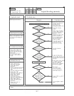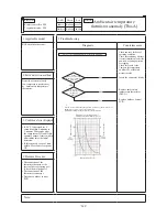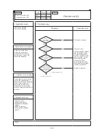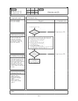
background image

Error code

Remote controller:
7-segment display:

LED

Green

Red

Indoor

Outdoor

Content

– 

360

 –

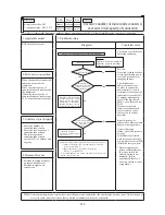
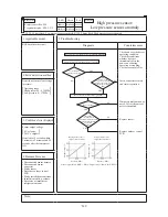
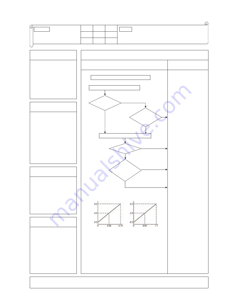
E54
E54-1, 2 *1

High pressure sensor/

Low pressure sensor anomaly

Keeps flashing Stays Off

Keeps flashing Stays Off*1

1. Applicable model

5. Troubleshooting

KXE6 multi outdoor unit

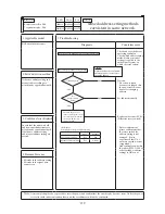
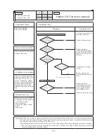
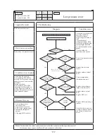
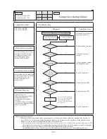
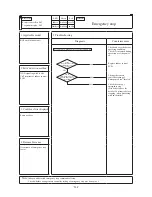
Diagnosis

Countermeasure

Is anomalous 

pressure detected?

Is the 

connector of the 

faulty sensor inserted 

properly to the connector on 

the outdoor control 

PCB?

Save data for 30 minutes before stopping in Mente PC

Reset the power and restart operation.

Check the data for 30 minutes before stopping

YES

YES

NO

YES

High pressure sensor 
output characteristics

Sensor output  Black (GND) – White; Output voltage (Black – Red; DC5V)

Pressure (MPa)

Pressure (MPa)

Low pressure sensor 
output characteristics

NO

NO

NO

Does it recur?

Does 

the pressure 

converted from the 

sensor output voltage match the 

actual pressure measure 

by pressure 

gauge?

YES

Output 

vo

ltage (V

)

Output 

vo

ltage (V

)

Check and save the data of 

operating condition.

Check the conditions 

whether it occurs 

immediately after the 

power on or during 

operation or stopping.

Check also sensor value.

Insert connector securely 

and restart operation.

Temporary malfunction by 

noise. Correct if source of 

noise is identified.

Replace sensor.

Replace outdoor control 

PCB.

2. Error detection method

Detection of anomalous voltage 

(pressure)

Operating range

High pressure 0 – 4.15MPa

Low pressure 0 – 1.7MPa

3. Condition of error displayed 

Sensor output voltage

0V or lower

3.49V or higher

Detected for 5 seconds within 

2 minutes to 2 minutes and 20 

seconds after the compressor 

ON.

4. Presumable cause

• Disconnected sensor harness

• Disconnected sensor 

connector

• Faulty sensor

• Defective outdoor control 

PCB

• Faulty installation conditions

• Insufficient airflow volume

• Excessive or insufficient 

refrigerant amount

Note:

*1 E54-1/1 time flash: Low pressure sensor anomaly, E54-2/2 times flash: High pressure sensor anomaly

[                                  ]

[                    ]

Summary of Contents for FDC112KXEN6

Page 1: ... 140KXE6 160KXE6 FDUM22KXE6 28KXE6 36KXE6 45KXE6 56KXE6 71KXE6 90KXE6 112KXE6 140KXE6 FDTC22KXE6 28KXE6 36KXE6 45KXE6 56KXE6 FDQS22KXE6 28KXE6 36KXE6 45KXE6 56KXE6 FDU71KXE6 90KXE6 112KXE6 140KXE6 FDFU28KXE6 45KXE6 56KXE6 71KXE6 FDTW28KXE6 45KXE6 56KXE6 71KXE6 90KXE6 112KXE6 140KXE6 FDK22KXE6 28KXE6 36KXE6 45KXE6 56KXE6 FDTQ22KXE6 28KXE6 36KXE6 FDFL28KXE6 45KXE6 71KXE6 FDTS45KXE6 71KXE6 FDE36KXE6 ...

Page 2: ...Same series KXE4 A 2004 6 YES C YES C YES C YES C NO NO NO YES C YES C NO Same series KXE4A 2004 11 NO NO YES C YES C NO NO NO NO YES C NO Mixed series KXE4A 2004 11 NO NO NO YES C NO NO NO NO YES C NO Mixed series KXE4A 2004 11 KXE6 2008 3 KXE6 2008 3 KXE6 2008 3 KXE6 2008 3 KXE4R 2006 3 KXE4BR 2007 4 KXE5R 2007 4 KXE4R 2006 3 KXE4BR 2007 4 KXE5R 2007 4 KXE4R 2006 3 KXE4BR 2007 4 KXE5R 2007 4 KXE...

Page 3: ... 15 d Ceiling cassette 1 way type FDTS 18 e Ceiling cassette 1 way compact type FDTQ 19 f Duct connected High static pressure type FDU 22 g Duct connected Low Middle static pressure type FDUM 24 h Duct connected Ultra thin Low static pressure type FDQS 28 i Wall mounted type FDK 30 j Ceiling suspended type FDE 32 k Floor standing with casing type FDFL 35 l Floor standing without casing type FDFU 3...

Page 4: ...ontroller Option parts 237 3 Installation of outdoor unit 238 4 Refrigerant piping 240 5 Electric wiring work 251 6 Controller settings 254 7 Test operation 263 8 Cautions for servicing for R410A and compatible machines 264 9 Setting function with the remote controller 264 10 Notabilia as a unit designed for R410A 275 4 6 Outline of operation control by microcomputer 276 1 Wired remote controller ...

Page 5: ...r Optimizing relationship of the air flow velocity fin pattern Improvement of air distribution Maximizing efficiency of heat exchanger b Compact Integrated PCB Control Box size reduction PCB size reduced by 50 Control PCB Single sided board aDouble sided board Inverter PCB Power transistor size reduction New Superlink system control New Design method applid 3 Design Flexibility a Increased indoor ...

Page 6: ...door unit 2 Indoor unit Example FDT 28 KX E 6 Series No Application power source See the specifications Multi series Nominal capacity nominal cooling capacity 2 8 kW Model name Indoor unit FDTC FDT FDTW FDTQ FDTS FDU FDUM FDQS FDE FDK FDFL FDFU Note For outdoor unit EN60552 2 and EN60555 3 are not applicable as consent by the utility company or notification to the utility company is given before u...

Page 7: ... 䡬 䡬 䡬 䡬 䡬 䡬 䡬 䡬 䡬 䡬 䡬 䡬 䡬 䡬 䡬 䡬 䡬 䡬 䡬 䡬 䡬 䡬 䡬 䡬 1 3 Table of models 1 4 Table of indoor units panel Optional Model Parts Model T PSA 36W E FDT Capacity 28 36 45 56 71 90 112 140 160 Capacity 22 28 36 Capacity 22 28 36 Capacity 28 45 56 Capacity 71 90 Capacity 112 140 Capacity 45 Capacity 71 TW PSA 24W E TW PSA 34W E TW PSA 44W E TQ PSA 15W E TQ PSB 15W E QR PNA 14W ER QR PNB 14W ER TS PSA 29W E T...

Page 8: ...ght Width Depth Refrigerant equipment compressor type Q ty Stucco white Exterior appearance color Noise level 1 The cooling and heating capabilities imply the values when the indoor unit of rated capacity is connected under the condition specified in ISO T1 List of branch pipe part numbers Select parts in accordance with the branching system used Note Air handling equipment Fan type Q ty Motor Sta...

Page 9: ...or dimensions Height Width Depth Refrigerant equipment compressor type Q ty Stucco white Exterior appearance color Noise level 1 The cooling and heating capabilities imply the values when the indoor unit of rated capacity is connected under the condition specified in ISO T1 List of branch pipe part numbers Select parts in accordance with the branching system used Note Air handling equipment Fan ty...

Page 10: ...ower outlet faces perpendicularly to the dominant wind direction 4 Leave a 1m or larger space above the unit 5 A wall in front of the blower outlet must not exceed the units height 6 The unit name plate is attached on the lower right corner of the front panel Z 51 40 36 100 845 10 110 50 195 242 279 970 50 15 55 50 27 52 110 50 195 B B A A Terminal block F C C VIEW Z C 50 15 70 50 150 40 F E 370 4...

Page 11: ... Orange Yellow Yellow Green Electrolytic capacitor Crankcase heater Compressor motor Connector Current sensor Diode module Electronic expansion valve For overcooling Electronic expansion valve For heating Fan motor Fuse High pressure sensor Intelligent power module Superlink terminal setting spare normal External input switch pulse level Defrost start temperature cold weather district normal React...

Page 12: ...ure switch Protection Mark Name Mark C CH CM CNA Z CT DM EEVSC EEVH FMo1 F PSH IPM J10 J13 J15 L LED1 LED2 LED3 PSL SW1 SW2 SW3 1 SW3 5 SW3 7 SW4 7 SW4 8 SW5 1 SW5 2 SW5 3 SW5 5 SW7 Button SW8 Button SW9 Button TB Tho A Tho D Tho P1 Tho R1 Tho S Tho SC Tho H 20S 63H1 1 WH CNW1 RD BK WH CNW2 RD BL WH CNR BL RD RD CNO1 G K WH CNI2 BL RD WH BK GL PWB2 PCB INVERTER BL RD BL BL DM R1 R2 U C1 U W V TB5 ...

Page 13: ...evel 53 dB A at 50Hz Souud Pressure Level standard 0 0002µ bar Mid Octave Band Frequency Hz N40 N50 N30 N60 N70 N80 63 125 250 500 1000 2000 4000 8000 30 40 50 60 70 80 30 40 50 60 70 80 Noise level 55 dB A at 60Hz Souud Pressure Level standard 0 0002µ bar Mid Octave Band Frequency Hz N40 N50 N30 N60 N70 N80 63 125 250 500 1000 2000 4000 8000 30 40 50 60 70 80 30 40 50 60 70 80 Models FDC155KXEN6 ...

Page 14: ... 60Hz Electronic Expansion Valve Direct line starting Possible Pocket plastic net 1 Washable Rubber sleeve for fan motor Polyurethane foam Flare piping Connectable with VP20 I D 20mm O D 26mm Drain pump Built in Drain pump Necessary both Liquid Gas line Mounting kit Drain hose Decorative Panel Thermostat by electronics Turbo fan 1 mm in Safety equipment Wired remote control switch Optional RC E3 W...

Page 15: ...nsion Valve Direct line starting Possible Pocket plastic net 1 Washable Rubber sleeve for fan motor Polyurethane foam Flare piping Connectable with VP20 I D 20mm O D 26mm Necessary both Liquid Gas lines Mounting kit Drain hose Decorative Panel Thermostat by electronics Turbo fan 1 Liquid line 6 35 1 4 Gas line 12 7 1 2 Liquid line 9 52 3 8 Gas line 15 88 5 8 mm in Safety equipment Wired remote con...

Page 16: ...r temperature Outdoor air temperature Standards ISO T1 Operation Model FDT90 112 140 160 type T PSA 36W E Panel Part No DB WB DB WB Cooling 1 27 Heating 2 20 19 35 7 24 6 Unit 298 840 840 Panel 35 950 950 Nominal cooling capacity 1 Nominal heating capacity 2 Power source Net weight Starting method Outside air intake Air filter Q ty Shock vibration isolator Insulation noise heat Room temperature co...

Page 17: ... 220V 60Hz Electronic Expansion Valve Direct line starting Not Possible Rubber sleeve for fan motor Polyurethane foam Flare piping Connectable with VP20 I D 20mm O D 26mm Necessary both Liquid Gas line Mounting kit Drain hose Decorative Panel Thermostat by electronics Turbo fan 1 mm in Safety equipment Wired remote control switch Optional RC E3 Wireless kit Optional RCN TC 24W ER Hi 35 Me 33 Lo 32...

Page 18: ...0 5 0 1 Phase 220 240V 50Hz 220V 60Hz Electronic Expansion Valve Direct line starting Not Possible Rubber sleeve for fan motor Polyurethane foam Flare piping Connectable with VP20 I D 20mm O D 26mm Necessary both Liquid Gas lines Mounting kit Drain hose Decorative Panel Thermostat by electronics Turbo fan 1 Liquid line 6 35 1 4 Gas line 12 7 1 2 mm in Safety equipment Wired remote control switch O...

Page 19: ...9 35 7 24 6 Turbo fan 1 Nominal cooling capacity 1 Nominal heating capacity 2 Power source Net weight Starting method Outside air intake Air filter Q ty Shock vibration isolator Insulation noise heat Room temperature control Connecting method Drain hose Insulation for piping Accessories Optional parts Motor Air flow Standard Exterior dimensions Height Width Depth Refrigerant equipment Heat exchang...

Page 20: ...DB WB Cooling 1 27 Heating 2 20 19 35 7 24 6 Turbo fan 1 Liquid line 9 52 3 8 Gas line 15 88 5 8 Nominal cooling capacity 1 Nominal heating capacity 2 Power source Net weight Starting method Outside air intake Air filter Q ty Shock vibration isolator Insulation noise heat Room temperature control Connecting method Drain hose Insulation for piping Accessories Optional parts Motor Air flow Standard ...

Page 21: ...WB DB WB Cooling 1 27 Heating 2 20 19 35 7 24 6 Turbo fan 2 Liquid line 9 52 3 8 Gas line 15 88 5 8 Nominal cooling capacity 1 Nominal heating capacity 2 Power source Net weight Starting method Outside air intake Air filter Q ty Shock vibration isolator Insulation noise heat Room temperature control Connecting method Drain hose Insulation for piping Accessories Optional parts Motor Air flow Standa...

Page 22: ...ominal heating capacity 2 Power source Net weight Starting method Outside air intake Air filter Q ty Shock vibration isolator Insulation noise heat Room temperature control Connecting method Drain hose Insulation for piping Accessories Optional parts Motor Air flow Standard Exterior dimensions Height Width Depth Refrigerant equipment Heat exchanger Operation control Operation switch Installation d...

Page 23: ... Panel 3 Unit 19 Panel 2 5 Unit 19 Panel 3 Unit 250 570 570 Panel 35 625 650 Unit 250 570 570 Panel 35 780 650 Unit 250 570 570 Panel 35 780 650 Nominal cooling capacity 1 Panel model Option Panel name Nominal heating capacity 2 Power source Net weight Starting method Outside air intake Air filter Q ty Shock vibration isolator Insulation noise heat Room temperature control Connecting method Drain ...

Page 24: ... 2 5 Unit 19 Panel 3 Unit 250 570 570 Panel 35 625 650 Unit 250 570 570 Panel 35 780 650 Unit 250 570 570 Panel 35 780 650 Nominal cooling capacity 1 Panel model Option Panel name Nominal heating capacity 2 Power source Net weight Starting method Outside air intake Air filter Q ty Shock vibration isolator Insulation noise heat Room temperature control Connecting method Drain hose Insulation for pi...

Page 25: ... 2 5 Unit 19 Panel 3 Unit 250 570 570 Panel 35 625 650 Unit 250 570 570 Panel 35 780 650 Unit 250 570 570 Panel 35 780 650 Nominal cooling capacity 1 Panel model Option Panel name Nominal heating capacity 2 Power source Net weight Starting method Outside air intake Air filter Q ty Shock vibration isolator Insulation noise heat Room temperature control Connecting method Drain hose Insulation for pi...

Page 26: ...ing 1 27 Heating 2 20 19 35 7 24 6 Centrifugal fan 2 Liquid line 9 52 3 8 Gas line 15 88 5 8 Nominal cooling capacity 1 Nominal heating capacity 2 Power source Net weight Starting method Outside air intake Air filter Q ty Shock vibration isolator Insulation noise heat Room temperature control Connecting method Drain hose Insulation for piping Accessories Optional parts Motor Air flow Standard Exte...

Page 27: ... 24 6 Centrifugal fan 2 Liquid line 9 52 3 8 Gas line 15 88 5 8 Nominal cooling capacity 1 Nominal heating capacity 2 Power source Net weight Starting method Outside air intake Air filter Q ty Shock vibration isolator Insulation noise heat Room temperature control Connecting method Drain hose Insulation for piping Accessories Optional parts Motor Air flow Standard Exterior dimensions Height Width ...

Page 28: ...ure Standards ISO T1 Operation DB WB DB WB Cooling 1 27 Heating 2 20 19 35 7 24 6 Centrifugal fan 2 Liquid line 6 35 1 4 Gas line 9 52 3 8 Nominal cooling capacity 1 Nominal heating capacity 2 Power source Net weight Starting method Outside air intake Air filter Q ty Shock vibration absorber Insulation noise heat Room temperature control Connecting method Drain hose Insulation for piping Accessori...

Page 29: ...ooling 1 27 Heating 2 20 19 35 7 24 6 Centrifugal fan 2 Liquid line 6 35 1 4 Gas line 12 7 1 2 Nominal cooling capacity 1 Nominal heating capacity 2 Power source Net weight Starting method Outside air intake Air filter Q ty Shock vibration absorber Insulation noise heat Room temperature control Connecting method Drain hose Insulation for piping Accessories Motor Air flow Standard Exterior dimensio...

Page 30: ...Centrifugal fan 2 Liquid line 9 52 3 8 Gas line 15 88 5 8 Nominal cooling capacity 1 Nominal heating capacity 2 Power source Net weight Starting method Outside air intake Air filter Q ty Shock vibration absorber Insulation noise heat Room temperature control Connecting method Drain hose Insulation for piping Accessories Motor Air flow Standard Exterior dimensions Height Width Depth Refrigerant equ...

Page 31: ...l fan 3 Liquid line 9 52 3 8 Gas line 15 88 5 8 Nominal cooling capacity 1 Nominal heating capacity 2 Power source Net weight Starting method Outside air intake Air filter Q ty Shock vibration absorber Insulation noise heat Room temperature control Connecting method Drain hose Insulation for piping Accessories Motor Air flow Standard Exterior dimensions Height Width Depth Refrigerant equipment Hea...

Page 32: ...7 Heating 2 20 19 35 7 24 6 Centrifugal fan 1 Liquid line 6 35 1 4 Gas line 9 52 3 8 Liquid line 6 35 1 4 Gas line 12 7 1 2 Nominal cooling capacity 1 Nominal heating capacity 2 Power source Net weight Starting method Outside air intake Air filter Q ty Shock vibration isolator Insulation noise heat Room temperature control Connecting method Drain hose Insulation for piping Accessories Optional par...

Page 33: ... 35 7 24 6 Centrifugal fan 1 Liquid line 6 35 1 4 Gas line 12 7 1 2 Nominal cooling capacity 1 Nominal heating capacity 2 Power source Net weight Starting method Outside air intake Air filter Q ty Shock vibration isolator Insulation noise heat Room temperature control Connecting method Drain hose Insulation for piping Accessories Optional parts Motor Air flow Standard Exterior dimensions Height Wi...

Page 34: ... 259 Nominal cooling capacity 1 Nominal heating capacity 2 Power source Net weight Starting method Outside air intake Air filter Q ty Shock vibration isolator Insulation noise heat Room temperature control Connecting method Drain hose Insulation for piping Accessories Optional parts Motor Air flow Standard Exterior dimensions Height Width Depth Refrigerant equipment Heat exchanger Operation contro...

Page 35: ...thod Outside air intake Air filter Q ty Shock vibration isolator Insulation noise heat Room temperature control Connecting method Drain hose Insulation for piping Accessories Optional parts Motor Air flow Standard Exterior dimensions Height Width Depth Refrigerant equipment Heat exchanger Operation control Operation switch Installation data Refrigerant piping size Noise level Safety equipment Refr...

Page 36: ... Nominal cooling capacity 1 Nominal heating capacity 2 Power source Net weight Starting method Outside air intake Air filter Q ty Shock vibration isolator Insulation noise heat Room temperature control Connecting method Drain hose Insulation for piping Accessories Optional parts Motor Air flow Standard Exterior dimensions Height Width Depth Refrigerant equipment Heat exchanger Operation control Op...

Page 37: ... 1070 690 36 Hi 41 Me 39 Lo 37 210 1320 690 Nominal cooling capacity 1 Nominal heating capacity 2 Power source Net weight Starting method Outside air intake Air filter Q ty Shock vibration isolator Insulation noise heat Room temperature control Connecting method Drain hose Insulation for piping Accessories Optional parts Motor Air flow Standard Exterior dimensions Height Width Depth Refrigerant eq...

Page 38: ...Me 44 Lo 43 Nominal cooling capacity 1 Nominal heating capacity 2 Power source Net weight Starting method Outside air intake Air filter Q ty Shock vibration isolator Insulation noise heat Room temperature control Connecting method Drain hose Insulation for piping Accessories Optional parts Motor Air flow Standard Exterior dimensions Height Width Depth Refrigerant equipment Heat exchanger Operation...

Page 39: ...1 225 Nominal cooling capacity 1 Nominal heating capacity 2 Power source Net weight Starting method Outside air intake Air filter Q ty Shock vibration isolator Insulation noise heat Room temperature control Connecting method Drain hose Insulation for piping Accessories Optional parts Motor Air flow Standard Exterior dimensions Height Width Depth Refrigerant equipment Heat exchanger Operation contr...

Page 40: ...5 32 630 1362 225 Nominal cooling capacity 1 Nominal heating capacity 2 Power source Net weight Starting method Outside air intake Air filter Q ty Shock vibration isolator Insulation noise heat Room temperature control Connecting method Drain hose Insulation for piping Accessories Optional parts Motor Air flow Standard Exterior dimensions Height Width Depth Refrigerant equipment Heat exchanger Ope...

Page 41: ...of 4000 or more between the units when installing more than one Note 1 The model name label is attached inside the air return grille 2 Prepare the connecting socket VP20 on site Obstacle 1000 or more 2500 or more VIEW G VIEW H Space for installation and service A B C D F G H FDT28KXE6 FDT36KXE6 45KXE6 56KXE6 FDT71KXE6 Content Symbol Model Gas piping Liquid piping Drain piping Hole for wiring Suspe...

Page 42: ... 207 840 123 173 298 35 Control box 50 or more G H H H Accessory C Holes for tapping screws Holes for tapping screws Hole Hole 140 100 100 60 140 140 65 105 112 137 40 38 05 50 37 76 67 13 44 6 4 5 4 700 or less 292 325 Max Drain lift A B C D F G H Gas piping Liquid piping Drain piping Hole for wiring Suspension bolts Outside air opening for ducting Air outlet opening for ducting Knock out Knock o...

Page 43: ...Installed at site Connectable with VP20 M10 or M8 Max Drain lift Air supply Air return grille 6 ø4 Holes for tapping screws Hole Obstacle 1000 or more 1000 or more Space for installation and service Decorative Panel Opening for exit wiring Unit mm Outlet air opening for ducting 413 The model name label is attached on the control box lid inside the air return grille Prepare the connecting socket VP...

Page 44: ...iping 28 ø9 52 3 8 45 56 ø12 7 1 2 Drain Connectable with VP20 Hole for wiring Ceiling hole size Space for installation and service 1000or more 680 160 160 360 45 45 965 1055 Air return Air supply A Hole Hole Hole Hole Unit mm Decorative Panel 95 127 278 264 310 91 64 47 98 Holes of tapping screws 5 φ4 Hole Suspension fitting Suspension bolts M10 4 pcs Outside air opening for ducting knock out VIE...

Page 45: ...0 Obstruction 1000or more 750 or less Max Drain lift Holes for tapping screws 8 φ4 Outlet air opening for ducting knock out Hole Hole A Unit mm Space for installation and service 680 160 160 360 45 45 1210 1300 Air return Air supply Decorative Panel 95 127 278 264 310 88 64 50 95 VIEW A Suspension fitting Outside air opening for ducting knock out Holes of taping screws 5 φ4 Hole Suspension bolts M...

Page 46: ...612 240 1524 672 66 295 325 8 357 Unit undersurface 67 255 100 140 Holes for tapping screws 8 ø4 Outlet air opening for ducting knock out 750 or less Max drain lift Hole Hole 240 200 240 200 Air return Air supply 1680 45 45 1770 160 160 360 680 20 620 410 364 310 230 20 10 10 247 170 299 Liquid piping ø9 52 3 8 Hole for wiring 1000 or more A Space for installation and service Decorative Panel Drai...

Page 47: ...e 100 or more 100 or more 140 70 200 250 150 50 100 290 50 435 180 90 60 25 168 85 940 Suspension bolts M10 4 pcs 555 35 45 70 290 45 25 40 60 315 285 70 Gas piping φ12 7 1 2 Liquid piping φ6 35 1 4 Drain Connectable with VP20 Hole for wiring φ35 370 215 275 415 30 45 650 15 30 110 172 105 155 Outside air opening for ducting Knock out Holes for tapping screws φ4 0 6 pcs 70 70 140 35 140 60 100 90 ...

Page 48: ... 250 200 50 50 35 100 100 Suspension bolts M10 4pcs 100 1200 200 295 325 165 194 600 or less 10 Max Drain lift C A B 70 30 210 1180 Air supply Air return grille 30 170 110 85 770 50 45 45 45 1410 1500 290 140 140 70 70 40 60 90 100 35 Drain 110 172 Connectable with VP20 Hole for wiring φ35 Gas piping φ15 88 5 8 Liquid piping φ9 52 3 8 155 105 415 650 15 30 45 30 370 275 215 Obstacle 100 or more 10...

Page 49: ...ide air opening for ducting Knock out Outside air opening for ducting Knock out Opening for exit wiring 68 30 150 150 30 30 490 30 37 5 100 37 5 155 150 45 210 140 42 248 197 135 φ 1 7 0 φ170 φ 1 2 5 φ125 138 B 139 570 35 250 288 288 21 269 259 576 273 61 65 21 528 295 325 63 570 Obstacle 550 600 255 138 125 210 625 514 650 580 100 or more 100 or more 1000 or more 100 or more or more 1500 85 or mo...

Page 50: ... center Suspension bolts Pitch Suspension bolts M10X4pcs Liquid piping φ6 35 1 4 Drain Connectable with VP20 Outside air opening for ducting Knock out Outside air opening for ducting Knock out Opening for exit wiring 68 30 150 150 30 30 490 30 37 5 100 37 5 155 150 45 210 140 42 248 197 135 φ 1 7 0 φ170 φ 1 2 5 φ125 138 139 570 35 250 288 288 21 36 36 269 259 576 82 82 Ceiling hole size 740 Ceilin...

Page 51: ...ping screws Cover Suspension bolts Pitch Control box or less Max Drain lift Panel center Suspension bolts Pitch Suspension bolts M10X4pcs Liquid piping φ6 35 1 4 Drain Connectable with VP20 Outside air opening for ducting Knock out Outside air opening for ducting Knock out Opening for exit wiring 68 30 150 150 30 30 490 30 37 5 100 37 5 155 150 45 210 140 42 248 197 135 φ 1 7 0 φ170 φ 1 2 5 φ125 1...

Page 52: ... out Opening for exit wiring 68 30 150 150 30 30 490 30 37 5 100 37 5 155 150 45 210 140 42 248 197 135 φ 1 7 0 φ170 φ 1 2 5 φ125 138 139 570 40 35 250 288 288 21 36 36 269 259 576 82 82 Ceiling hole size 740 Ceiling hole size 600 273 61 65 21 528 295 325 63 570 Obstacle 550 600 255 138 125 210 780 650 580 100 or more 100 or more 100 or more 1000 or more B A Space for installation and service 85 o...

Page 53: ...The model name label is attached on the lid of the control box Prepare the connecting socket VP20 on site Note 1 2 Gravity drainage Suspension bolts Hole for wiring Inspection hole M10 VP20 Note 2 VP20 15 88 5 8 Flare 9 52 3 8 Flare Space for installation and service 886 Suspension bolts pitch Suspension bolts pitch Control box 10 4 292 325 Holes for tapping screws Air supply Max Drain lift 600 or...

Page 54: ...vice 1406 Suspension bolts pitch Suspensionboltspitch Control box 14 4 Holes for tapping screws Air supply Max Drain lift 560 45 45 650 30 30 350 477 80 240 101 151 265 420 482 527 53 1720 100 1370 635 600 85 27 297 19 19 43 43 16 16 9 43 325 43 26 58 77 284 50 1370 50 27 297 19 19 43 43 1470 4X325 1300 28 249 9 173 32 32 249 16 16 9 43 325 4X325 1300 43 9 C2 E F D A B 295 325 600 or more Hanger p...

Page 55: ...crews 786 Suspension bolts pitch Unit mm Holes for tapping screws Hole of tapping screws Air supply duct 295 325 Suspension bolts pitch A B Control box VIEW A VIEW B Liquid piping Outlet air opening for ducting Knock out Knock out Fresh air opening for ducting Gas piping 6 35 1 4 9 52 3 8 4 4 170 149 170 Drain hose piece Accessory Installed on site Duct dimension 200 Duct dimension Hole for wining...

Page 56: ...g screws 786 Suspension bolts pitch Unit mm Holes for tapping screws Air supply duct 295 325 Suspension bolts pitch Control box VIEW A VIEW B Liquid piping Outlet air opening for ducting Knock out Knock out Fresh air opening for ducting Gas piping 6 35 1 4 12 7 1 2 4 4 170 149 170 Drain hose piece Accessory Installed on site Duct dimension 200 Duct dimension Hole for wining Connectable with VP25 D...

Page 57: ...nsion bolts pitch Unit mm Holes for tapping screws Air supply duct 295 325 Suspension bolts pitch A B Control box VIEW A VIEW B Liquid piping Outlet air opening for ducting Knock out Knock out Fresh air opening for ducting Gas piping 9 52 3 8 15 88 5 8 4 4 170 149 170 Drain hose piece Accessory Installed on site 860 Duct dimension 200 Duct dimension Hole for wining Connectable with VP25 Drain Grav...

Page 58: ... for tapping screws 1406 Suspension bolts pitch Unit mm Holes of tapping screws Air supply duct 295 325 Suspension bolts pitch A Control box VIEW A VIEW B Outlet air opening for ducting Knock out Knock out Fresh air opening for ducting Gas piping 9 52 3 8 15 88 5 8 4 4 170 149 170 Drain hose piece Accessory Installed on site Duct dimension Hole for wining Connectable with VP25 Drain Gravity draina...

Page 59: ...10 35 9 52 3 8 Flare 6 35 1 4 Flare 30 12 7 1 2 Flare Symbol FDQS22KXE6 28KXE6 FDQS36KXE6 45KXE6 56KXE6 Space for installation and service 292 325 12 4 990 Suspension bolts pitch Control box Suspension bolts pitch Drain hose piece Installed at site Accessory Hanger plate for suspension bolt Holes for tapping screws 600 or less Max Drain lift 880 Duct dimension Duct dimension 910 Duct dimension Duc...

Page 60: ...installation and service 292 325 12 4 12 4 990 Suspension bolts pitch Control box Suspension bolts pitch Drain hose piece Installed at site Accessory Hanger plate for suspension bolt Holes for tapping screws Holes for tapping screws 600 or less Max Drain lift 880 Duct dimension Duct dimension 910 Duct dimension Duct dimension 12 4 Holes for tapping screws Supply air duct Return air duct Celing ret...

Page 61: ...iquid piping Hole on wall for right rear piping Hole on wall for left rear piping Outlet for wiring Outlet for piping on both side Drain piping 9 52 3 8 Flare 6 35 1 4 Flare 65 65 12 7 1 2 Flare Symbol FDK22 28KXE6 FDK36 46 56KXE6 67 Right 60 Left Outlet for down piping Refer to the above view Space for installation and service when viewing from the front Service space Service space 4 12X18 Slot h...

Page 62: ...or piping On both side Outlet for electric wiring Service space Service space Long hole Indoor unit Mounting plate Outlet for piping 4 12X18 4 4 Space for installation and service ø9 52 3 8 Liquid piping ø15 88 5 8 Gas piping Long hole 2 5X17 5 77 53 5 633 5 703 5 772 7 7 44 5 44 5 301 8 8 5 50 50 450 349 299 106 886 106 65 50 49 5 221 5 25 25 46 225 43 610 219 269 Hole on wall for rear connection...

Page 63: ...ping inside the unit is able to take decline of 10mm 5 100 300 150 5 75 110 135 308 40 40 1240 1320 173 210 5 215 24 24 690 195 235 271 53 109 52 68 410 135 10 53 145 76 1272 Suspension bolts pitch 290 Suspension bolts pitch Air supply grille ø9 52 3 8 ø15 88 5 8 Holes for suspension bolts M8 to M10 4pcs Not included Liquid piping Gas piping Liquid piping Gas piping Space for installation and serv...

Page 64: ...88 5 8 Holes for suspension bolts M8 to M10 4pcs Not included Liquid piping Gas piping Liquid piping Gas piping Space for installation and service or more or more or more or more Obstacles Air return grille Drain hole connection 1 VP20 Drain hole connection 1 VP20 Drain hole connection 1 VP20 Note 1 The slope of drain piping inside the unit is able to take decline of 10mm Models FDE112KXE6 140KXE6...

Page 65: ...nstallation and service Note 1 Value in indicates 71 type 195 630 250 220 225 197 80 205 205 180 23 10 126 166 177 93 148 223 184 234 315 223 195 806 1091 197 225 32 98 Slotted hole for wall mounting 4 12 24 Floor fixing metal brakcet Accessory 10 30 long hole Drain piping Flexible tube PT20A female screw Gas piping Accessory 28 ø9 52 3 8 45 φ12 7 1 2 71 φ15 88 5 8 Liquid piping 28 45 φ6 35 1 4 71...

Page 66: ...r Optional parts Wired remote controller Model RC E3 Unit mm This side is not grounded Earth wiring Remote controller Remote controller cord Shielded wire Precation in extending the remote controller cord The cord should be a shielded wire For all types 0 3mm2 2 cores Note 1 Use cables up to 0 5mm2 maximum for those laid inside the remote controller casing and connect to a different size cable at ...

Page 67: ... Y GN Y GN RD BL BR OR WH Meaning of marks X4 Outdoor unit address ones place Automatic adjustment Fixed previous version of Superlink protocol Indoor unit address hundreds place Model capacity setting Operation check Drain motor test run Terminal block Power source mark Terminal block Signal line mark Thermistor Remote controller Thermistor Return air Thermistor Heat exchanger Relay for DM Closed...

Page 68: ...source line Notes Color marks BK BL BR GR OR P RD WH Y Y GN Black Blue Brown Gray Orange Pink Red White Yellow Yellow Green Mark Color Connector Drain motor Fuse Fan motor Float switch Live Superlink terminal setting for spare Indication lamp Green Normal operation Indication lamp Red Inspection Louver motor CNA Z DM LM1 4 FS F200 203 LED 2 LED 3 JSL1 FMI Meaning of marks Stepping motor for electr...

Page 69: ...ng for spare Indication lamp Green Normal operation Indication lamp Red Inspection Louver motor Stepping motor for electronic expansion valve Indoor unit address tens place Indoor unit address ones place Outdoor unit address tens place CNA Z Meaning of marks CFI1 Capacitor for FMI Fan motor with thermostat Louver switch X1 3 6 TB2 X4 X5 TB1 SW4 Outdoor unit address ones place Automatic adjustment ...

Page 70: ...ication lamp Green Normal operation Indication lamp Red Inspection Louver motor Stepping motor for electronic expansion valve Indoor unit address tens place Indoor unit address ones place Outdoor unit address tens place CNA Z Meaning of marks CFI1 Capacitor for FMI Fan motor with thermostat Louver switch X1 3 6 TB2 X4 X5 TB1 SW4 Outdoor unit address ones place Automatic adjustment Fixed previous v...

Page 71: ...al operation Indication lamp Red Inspection Louver motor Stepping motor for electronic expansion valve Indoor unit address tens place Indoor unit address ones place Outdoor unit address tens place CNA Z Meaning of marks CFI1 Capacitor for FMI Fan motor with thermostat Louver switch X1 3 6 TB2 X4 X5 TB1 SW4 Outdoor unit address ones place Automatic adjustment Fixed previous version of Superlink pro...

Page 72: ...Relay for DM Relay for LM mark Closed end connector ThI A ThI R1 2 3 Thc TrI Color marks Black Blue Brown Gray Light Blue Light Green Orange Pink Red White Yellow Yellow Green Mark Color BK BL BR GR P RD WH Y Y GN LB LG OR CNK2 SW2 SW1 SW3 SW4 JSL1 F 0 16A Option CNW0 CNM3 L N RD RD BR BR CNW2 19V 24V CNF1 FMI1 CNR 3 1 X4 RD RD CNW1 FS CNT 5 1 2 3 4 CNN 5 6 1 2 CNH CNN2 RD RD OR OR BK 3 OR CNJ2 1 ...

Page 73: ...WH X5 LM BK BK LS CNS3 CNJS CNS BL BL CNU WH RD 1 2 3 4 5 6 CNA M SM BR WH CNR2 DM CNT2 CNL6 1 3 2 5 4 7 6 9 8 1011 CNL4 CNL2 CNL1 CNL5 CNL3 WH Y OR BL BR RD CNA2 CNI CNI2 A B X Y X Y CNK1 CNB WH OR BR BL Y LG P BK RD GR LB RD RD BK BK Y Y OR WH WH 220 240V Tr WH Y OR BL BR RD BK BK BK RD WH RD X1 3 UH BR WH C WH 1 1 X6 M H BK BL 5 7 L RD 9 X3 X2 3 BK BK TB1 SW6 SW5 SW7 BK WH CNF2 WH WH WH XR1 XR2...

Page 74: ...e Notes Color marks BK BL BR GR OR Black Blue Brown Gray Orange Red White Yellow Yellow Green Color Mark Color Meaning of marks Connector Drain motor Fuse Float switch Live Superlink terminal setting for spare Indication lamp Green Normal operation Indication lamp Red Inspection Louver motor Capacitor for FMI Fan motor with thermostat Louver switch Stepping motor for electronic expansion valve Ind...

Page 75: ... Inspection Capacitor for FMI Fan motor with thermostat Stepping motor for electronic expansion valve Indoor unit address tens place Indoor unit address ones place Outdoor unit address tens place Outdoor unit address ones place Automatic adjustment Fixed previous version of Superlink protocol Indoor unit address hundreds place Model capacity setting Operation check Drain motor test run Terminal bl...

Page 76: ...B 1 RD 1 WH BK WH TB2 BL RD BL CNU WH RD RD FS N RD BK BK SW7 1 2 GR GR 5 6 3 4 BK 1 2 CNN Y RD BR BR 24V 6 RD 2 BL CNK1 WH CNT2 XB1 RD 12 1 2 3 4 5 XB2 XB3 XB4 BL CNR2 CNR WH WH RD Y GN BK BK BK BK BK BK CNK2 t JSL1 t t t t RD BK WH BL C L M UH H DM 3 1 X4 BR WH Y Y WH BR Option WH Y GN OR Y 52FH 52FM 52FL WH WH WH WH RD WH RD P P P F 5A F 5A BK BL RD BK BL RD C UH M L 52FH 52FM 52FL X Y X Y A M ...

Page 77: ... 1 X1 3 6 TB2 X4 TB1 Terminal block Power source mark Terminal block Signal line mark Thermistor Return air Thermistor Remote controller Thermistor Thermistor Heat exchanger Relay for FM Relay for DM ThI A ThI R1 2 3 Thc TrI Color marks Black Blue Brown Gray Orange Red White Yellow Yellow Green Mark Color BK BL BR GR RD WH Y Y GN OR SW6 SW5 SW2 SW1 SW4 SW3 SW7 CNK2 XR1 XR2 XR3 XR4 1 2 3 4 5 6 F 0 ...

Page 78: ...Terminal block Signal line mark Thermistor Return air Thermistor Remote controller Thermistor Thermistor Heat exchanger Relay for FM Relay for DM ThI A ThI R1 2 3 Thc TrI Color marks Black Blue Brown Gray Orange Red White Yellow Yellow Green Mark Color BK BL BR GR RD WH Y Y GN OR SW6 SW5 SW2 SW1 SW4 SW3 SW7 CNK2 XR1 XR2 XR3 XR4 1 2 3 4 5 6 F 0 16A TB2 2 1 4 3 2 1 6 5 XB1 XB2 XB3 XB4 1 2 3 4 5 Opti...

Page 79: ...in motor test run Terminal block Power source mark Terminal block Signal line mark Thermistor Return air Thermistor Remote controller Thermistor Thermistor Heat exchanger Relay for FM Relay for DM CNM3 WH C 1 3 H M 5 7 L 9 WH CNF1 I FM X1 X6 X3 X2 CNR 3 1 WH X4 CNI BL WH CNW1 220 240V TB1 WH RD CNW0 WH CNU 1 3 RD RD BL CNR2 DM BL FS N L 1 2 3 4 5 6 CNA RD t t 1 2 3 4 CNN 5 6 1 2 t t SW2 SW6 SW5 SW...

Page 80: ...del capacity setting Operation check Drain motor test run Terminal block mark Thermistor Remote controller mark Meaning of marks Fan motor with thermostat Thermistor Return air Thermistor Remote controller Thermistor Thermistor Heat exchanger ThI A ThI R1 2 3 Thc TrI 1 indicates wiring on site 2 Use twin core cord 0 75 1 25mm2 at signal line between indoor unit and outdoor unit and signal line bet...

Page 81: ...tion check Drain motor test run Terminal block mark Thermistor Remote controller mark Meaning of marks Fan motor with thermostat Thermistor Return air Thermistor Remote controller Thermistor Thermistor Heat exchanger ThI A ThI R1 2 3 Thc TrI 1 indicates wiring on site 2 Use twin core cord 0 75 1 25mm2 at signal line between indoor unit and outdoor unit and signal line between indoor units 3 Use tw...

Page 82: ...e Superlink terminal setting for spare Indication lamp Green Normal operation Meaning of marks FMI1 2 F LM SM LED 3 LED 2 JSL1 CNA Z CFI1 2 SW1 SW2 SW3 SW4 Indoor unit address tens place Indoor unit address ones place Outdoor unit address tens place Outdoor unit address ones place Connector Fuse Indication lamp Red Inspection Louver motor Stepping motor for electronic expansion valve Capacitor for...

Page 83: ...dication lamp Green Normal operation Meaning of marks FMI1 2 F LM SM LED 3 LED 2 JSL1 CNA Z CFI1 2 SW1 SW2 SW3 SW4 Indoor unit address tens place Indoor unit address ones place Outdoor unit address tens place Outdoor unit address ones place Connector Fuse Indication lamp Red Inspection Louver motor Stepping motor for electronic expansion valve Capacitor for FMI Fan motor with thermostat Power sour...

Page 84: ...Y Y GN OR GR Color marks X1 3 6 TB2 TB1 FMI F SW1 SM SW2 LED 3 LED 2 SW3 SW4 JSL1 Connector Fuse Live Superlink terminal setting for spare Indication lamp Green Normal operation Indication lamp Red Inspection Stepping motor for electronic expansion valve Indoor unit address tens place Indoor unit address ones place Outdoor unit address tens place Outdoor unit address ones place Automatic adjustmen...

Page 85: ...H Y Y GN OR GR Color marks X1 3 6 TB2 TB1 FMI F SW1 SM SW2 LED 3 LED 2 SW3 SW4 JSL1 Connector Fuse Live Superlink terminal setting for spare Indication lamp Green Normal operation Indication lamp Red Inspection Stepping motor for electronic expansion valve Indoor unit address tens place Indoor unit address ones place Outdoor unit address tens place Outdoor unit address ones place Automatic adjustm...

Page 86: ...TC Decorative panel Decorative panel c Ceiling cassette 2 way type FDTW Decorative panel Standard type Panel part No Type Panel color Applicable model TW PSA 24W E TW PSA 34W E TW PSA 44W E With Auto swing Plaster white FDTW28 45 56 FDTW71 90 FDTW112 140 Air return Air supply Plaster white Plaster white ...

Page 87: ...hite Decorative panel e Ceiling cassette 1 way type FDTQ This illustration shows the direct blow panel TQ PSA 15W E Painting color is the same for other panels Plaster white Panel part No Direct blow panel Duct panel TQ PSA 15W E TQ PSB 15W E QR PNA 14W ER QR PNB 14W ER With Auto swing Plaster white Non Auto swing Plaster white FDTQ22 28 36 FDTQ22 28 36 Type Panel color Applicable model Decorative...

Page 88: ...sion type FDE j Wall mounted type FDK Cool white Models FDK22 28 36 45 56KXE6 Plaster white Front panel Light gray Horizontal louver Light gray Vertical louver Plaster white Air return grille Plaster white Front panel Plaster white Side panel Model FDK71KXE6 Cool white k Floor standing with casing type FDFL Dark gray Air supply grill Ceramic white Body Black Bottom plate l Floor standing without c...

Page 89: ...gh speed 4 Stan dard High 4 speed Stan dard High speed 1 Square duct Air flow m3 min 10 12 14 18 20 28 34 50 40 50 40 50 40 50 40 50 45 60 60 60 55 85 90 85 90 85 90 85 100 85 100 90 100 85 100 40 45 40 45 50 45 55 100 55 50 65 65 65 65 65 75 65 75 90 90 90 100 90 105 95 105 95 105 Unit Pa 40 20 0 20 14 13 16 18 20 10 Static pressure Pa Air flow m3 min 3 spot blower internal resistance S t a n d a...

Page 90: ...e d H i g h H i g h s p e e d M e d i u m H i g h s p e e d M e d i u m H i g h s p e e d L o w H i g h s p e e d L o w S t a n d a r d L o w S t a n d a r d L o w S t a n d a r d M e d i u m S t a n d a r d H i g h S t a n d a r d H i g h 100 80 60 40 20 20 10 12 14 Static pressure Pa Standard 2 spot blower internal resistance Square duct blower internal resistance Square duct blower internal res...

Page 91: ... Upper limit High speed Low limit H i g h s p e e d H i g h H i g h s p e e d M e d i u m H i g h s p e e d L o w S t a n d a r d L o w S t a n d a r d M e d i u m S t a n d a r d H i g h High speed Upper limit Standard Upper limit High speed Low limit H i g h s p e e d H i g h H i g h s p e e d M e d i u m H i g h s p e e d L o w S t a n d a r d L o w S t a n d a r d M e d i u m S t a n d a r d H...

Page 92: ...10 Standard 4 spot blower internal resistance Square duct blower internal resistance Standard Upper limit High speed Low limit High speed Low S t a n d a r d L o w S t a n d a r d M e d i u m Standard High Static pressure Pa 3 spot blower internal resistance Air flow m3 min Lower limit Upper limit 21 25 28 31 100 120 80 60 40 20 10 Static pressure Pa Air flow m3 min Lower limit Upper limit High sp...

Page 93: ... n d a r d H i g h Static pressure Pa 3 spot blower internal resistance Standard 4 spot blower internal resistance Square duct blower internal resistance High speed Upper limit Standard Upper limit High speed Low limit H i g h s p e e d H i g h H i g h s p e e d M e d i u m H i g h s p e e d L o w S t a n d a r d L o w S t a n d a r d M e d i u m S t a n d a r d H i g h 3 spot blower internal resi...

Page 94: ... Pa Model FDU90KXE6 Model FDU71KXE6 0 20 40 60 80 100 120 140 160 180 200 20 21 22 23 24 25 26 27 28 29 30 Upper limit 50 Standard pressure Standard air flow Lower limit Air flow m3 min Static pressure Pa Standard Upper limit High speed Upper limit High speed Upper limit High speed Lower limit High speed Lower limit High speed High High speed High H i g h s p e e d L o w H i g h s p e e d L o w S ...

Page 95: ...wer limit Static pressure Pa Upper limit Upper limit L M H Standard 15Pa Max 30Pa 7 8 9 10 11 12 0 Static pressure Upper limit Standard 15Pa Max 30Pa Static pressure 40 35 30 25 20 15 10 5 7 8 9 10 11 12 13 14 15 Static pressure Pa L M H 0 Air flow m3 min Lower limit Upper limit Air flow m3 min Models FDQS45 56KXE6 ...

Page 96: ...0 N40 N30 N20 60 60 N10 Souud Pressure Level dB standard 0 0002µ bar Mid Octave Band Frequency Hz N60 40 50 40 50 63 125 250 500 1000 2000 4000 8000 10 20 30 10 20 30 N50 N40 N30 N20 60 60 N10 Souud Pressure Level dB standard 0 0002µ bar Mid Octave Band Frequency Hz Model FDT71KXE6 b Ceiling cassette 4 way type FDT Measured based on JIS B 8616 Mike position as right 1 5m Mike center low points N60...

Page 97: ...at MEDIUM 39 dB A at LOW Souud Pressure Level dB standard 0 0002µ bar Mid Octave Band Frequency Hz N30 N40 N20 N50 N60 N70 63 125 250 500 1000 2000 4000 8000 20 30 40 50 60 70 20 30 40 50 60 70 Souud Pressure Level dB standard 0 0002µ bar Mid Octave Band Frequency Hz N30 N40 N20 N50 N60 N70 63 125 250 500 1000 2000 4000 8000 20 30 40 50 60 70 20 30 40 50 60 70 Souud Pressure Level dB standard 0 00...

Page 98: ...Hz d Ceiling cassette 1 way compact type FDTQ Measured based on JIS B 8616 Mike position as below 1 5m Mike center low points e 1 way outlet ceiling recessed type FDTS Measured based on JIS B 8616 Mike position as below 1 5m Mike center low points 1 5m f Duct connected High static pressure type FDU Measured based on JIS B 8616 Mike position as right Souud Pressure Level dB standard 0 0002µ bar Mid...

Page 99: ...0 40 50 60 70 20 30 40 50 60 70 Mid Octave Band Frequency Hz N30 N40 N20 N50 N60 N70 63 125 250 500 1000 2000 4000 8000 20 30 40 50 60 70 20 30 40 50 60 70 Mid Octave Band Frequency Hz Mid Octave Band Frequency Hz N30 N40 N20 N50 N60 N70 63 125 250 500 1000 2000 4000 8000 20 30 40 50 60 70 20 30 40 50 60 70 N30 N40 N20 N50 N60 N70 63 125 250 500 1000 2000 4000 8000 20 30 40 50 60 70 20 30 40 50 60...

Page 100: ...ve Band Frequency Hz N30 N40 N20 N50 N60 N70 63 125 250 500 1000 2000 4000 8000 20 30 40 50 60 70 20 30 40 50 60 70 Souud Pressure Level dB standard 0 0002µ bar Mid Octave Band Frequency Hz N30 N40 N20 N50 N60 N70 63 125 250 500 1000 2000 4000 8000 20 30 40 50 60 70 20 30 40 50 60 70 1 5m Model FDQS22 28 36KXE6 Noise level Rear air return Noise level 37 dB A at HIGH Noise level 35 dB A at MEDIUM N...

Page 101: ...00 4000 8000 20 30 40 50 60 70 20 30 40 50 60 70 Model FDK56KXE6 Noise level 46 dB A at HIGH 39 dB A at MEDIUM 37 dB A at LOW Model FDK71KXE6 Noise level 47 dB A at HIGH 43 dB A at MEDIUM 39 dB A at LOW Souud Pressure Level dB standard 0 0002µ bar Mid Octave Band Frequency Hz N30 N40 N20 N50 N60 N70 63 125 250 500 1000 2000 4000 8000 20 30 40 50 60 70 20 30 40 50 60 70 Souud Pressure Level standar...

Page 102: ...n be connected the operation characteristics of all combinations are very complicated therefore only the individual operation characteristics of indoor and outdoor units are shown a Operating characteristic of outdoor unit Item Models FDC140KXEN6 FDC112KXEN6 Item Model FDC155KXES6 Item Model FDC112KXES6 FDC155KXEN6 0 12 34 56 5 2 7 2 8519 Item Model FDC140KXES6 i 1 phase ii 3 phase ...

Page 103: ...m FDUM Series 22 28 36 45 56 71 90 112 140 6 78 6 78 Models FDUM Series 4 5 Item FDTW Series 28 45 56 71 90 112 140 6 78 6 78 6 78 Models FDTW Series 4 5 Item FDTQ Series 22 28 36 6 78 6 78 6 78 6 78 Models FDTQ Series 4 5 Item FDTS Series 6 78 6 78 Models FDTS Series 4 5 Item FDT Series 71 90 28 36 45 56 6 78 6 78 Models FDT Series 4 5 Item FDT Series Models b Operating characteristic of indoor u...

Page 104: ...els FDQS Series 01 2 3 4 5 6 7 8 7 8 8 Item 112 3 9 9 3 9 9 56 45 36 71 3 9 9 FDE Series Models FDE Series Item 22 28 36 3 9 9 45 56 71 28 45 56 71 Models FDK FDFL FDFU Series FDK Series FDFL FDFU Series Item 140 3 9 9 3 9 9 FDE Series Model ...

Page 105: ...e 100 Total operation characteristics Operation characteristic value of outdoor unit Operation characteristic value of indoor unit Note 1 3phase only Example Conditions Operation Voltage Indoor unit 220 V 50 Hz Outdoor unit 380 V 50 Hz Operation mode Cooling and Heating Unit Outdoor unit FDC112KXES6 1 unit Indoor unit FDT71KXE6 1 units FDT45KXE6 2 units Item Models FDC112KXES6 FDT71KXE6 FDT45KXE6 ...

Page 106: ...it is higher Outdoor unit is lower Indoor units that can be used in combination Difference in height between indoor and outdoor units Difference in height between indoor units Indoor unit atmosphere behind ceiling temperature and humidity 1 cycle time Stop time Voltage fluctuation Phase unbalance Compressor stop start frequency Power source voltage Voltage drop during start Allowable length of ref...

Page 107: ...itions Precaution In case of severely low temperature condition 1 Install the outdoor unit at the place where strong wind cannot blow directly into the outdoor unit 2 If there is no installation place where can prevent strong wind from directly blowing into the outdoor unit mount the flex flow adaptor prepared as optional part or like such devices onto the outdoor unit in order to divert the stron...

Page 108: ...R2 Thermister Heat Thi R2 Thermister Outlet Thi R3 Outdoor unit Cooling cycle Heating cycle High pressure PSH High pressure 63H1 1 Low pressure sensor PSL Thermister Tho s Thermister 2 Compressor accumulator Compressor Tho H 4 way valve Check valve Service valve Thermister Tho D1 Thermister 1 Tho SC Liquid piping ø9 52 Charge port Oil separater ST ST EEVSC EEV Electric expansion valve ST Strainer ...

Page 109: ...unit Calculate the temperature compensation then calculate the indoor unit capacity See item 2 a for the calculation method Calculate temperature compensation and piping compensation etc then calculate the outdoor unit capacity See item 2 b for the calculation method Select the outdoor unit tentative Calculate the system capacity See item 2 c for the calculation method Calculate the indoor unit ca...

Page 110: ...gher c Calculating system capacity Compare the capacities determined in items a and b above and let the smaller value be the system capacity cooling heating q In cases where indoor unit total capacity cooling heating outdoor unit capacity cooling heating System capacity cooling heating Outdoor unit capacity cooling heating w In cases where indoor unit total capacity cooling heating outdoor unit ca...

Page 111: ...icient according to temperature conditions 0 95 Calculated according to Indoor 18 C WB Outdoor 35 C DB See page 108 Outdoor unit cooling capacity 14 0 kW 0 95 13 3 kW Capacity compensation coefficient according to piping length 0 87 calculated according to 60 m length See page 110 13 3 kW 0 87 11 6 kW Capacity compensation coefficient according to height difference 1 0 the outdoor unit is higher d...

Page 112: ...acity and the outdoor unit maximum heating capacity The smaller value is the actual system heating capacity Indoor unit total heating capacity 19 8 kW Outdoor unit maximum heating capacity 15 4 kW e System heating capacity 15 4 kW Indoor unit heating capacity compensation Item 2 d calculation 15 4 kW 6 6 kW 5 1 kW 19 8 kW 3 Capacity compensation coefficient a Capacity compensation coefficient and ...

Page 113: ... 00 1 05 1 10 1 15 1 20 17 18 19 20 21 22 23 24 Indoor air D B temperature CDB Indoor air W B temperature 14 CWB Indoor air W B temperature 15 CWB Indoor air W B temperature 16 CWB Indoor air W B temperature 17 CWB Indoor air W B temperature 18 CWB Indoor air W B temperature 19 CWB Indoor air W B temperature 20 CWB Indoor air W B temperature 21 CWB Indoor air W B temperature 22 CWB Indoor air W B ...

Page 114: ...air W B temperature 6 CWB Ambient air W B temperature 2 CWB Ambient air W B temperature 10 CWB 16 17 18 19 20 21 22 23 24 Indoor air D B temperature CDB Power consumption compensation coefficient 0 70 0 75 0 80 0 85 0 90 0 95 1 00 1 05 1 10 1 15 1 20 1 25 SHeating Note 1 Equivalent piping length can be obtained by calculating as follows Equivalent piping length Real gas piping length Number of ben...

Page 115: ... 35 m 0 93 50 m 0 90 f The capacity compensation coefficient and power consumption compensation coefficient vary according to the total capacity of concurrently operating indoor units as shown below 11 0 95 13 0 96 20 0 96 15 0 96 9 0 94 7 0 93 5 0 91 3 0 88 1 0 86 1 0 87 3 0 92 5 or more 1 Air inlet temperature of outdoor unit in C WB Adjustment coefficient Capacity compensation coefficient Power...

Page 116: ... 112 4 Sensible heat capacity ...

Page 117: ... 113 ...

Page 118: ... 114 ...

Page 119: ... 115 ...

Page 120: ... 116 ...

Page 121: ... 117 ...

Page 122: ... 118 ...

Page 123: ... 119 ...

Page 124: ... 120 ...

Page 125: ... 121 ...

Page 126: ... 122 ...

Page 127: ... 123 ...

Page 128: ... 124 ...

Page 129: ... 125 ...

Page 130: ... 126 ...

Page 131: ... 127 ...

Page 132: ... 128 ...

Page 133: ... 129 ...

Page 134: ... 130 ...

Page 135: ... 131 ...

Page 136: ... 132 ...

Page 137: ... 133 ...

Page 138: ... 134 ...

Page 139: ... 135 ...

Page 140: ... 136 ...

Page 141: ... 137 ...

Page 142: ... 138 ...

Page 143: ... 139 ...

Page 144: ... 140 ...

Page 145: ... 141 ...

Page 146: ... 142 ...

Page 147: ... 143 ...

Page 148: ... 144 ...

Page 149: ... 145 ...

Page 150: ... 146 ...

Page 151: ... 147 ...

Page 152: ... 148 ...

Page 153: ... 149 ...

Page 154: ... 150 ...

Page 155: ... 151 ...

Page 156: ... 152 ...

Page 157: ... 153 ...

Page 158: ... 154 ...

Page 159: ... 155 ...

Page 160: ... 156 ...

Page 161: ... 157 ...

Page 162: ... 158 ...

Page 163: ... 159 ...

Page 164: ... 160 ...

Page 165: ... 161 ...

Page 166: ... 162 ...

Page 167: ... 163 ...

Page 168: ... 164 ...

Page 169: ... 165 ...

Page 170: ... 166 ...

Page 171: ... 167 ...

Page 172: ... 168 ...

Page 173: ... 169 ...

Page 174: ... substance other than the specified refrigerant R410A such as air from entering the refrigerant cycle in installing or moving the air conditioning system Contamination by air or a foreign substance can cause an abnormal pressure build up inside the refrigerant cycle and a resultant explosion and personaly injury Use only parts supplied with the unit and specified supply parts for installation The ...

Page 175: ...to 20mm thick for entire surface of indoor unit refrigeration pipe and drain pipe Areas where TV and radio stays away more than 1m It could cause jamming and noise Areas where any items which will be damaged by getting wet are not placed such as food table wares server or medical equipment under the unit Areas where there is no influence by the heat which cookware generates Areas where not exposed...

Page 176: ... or the gap between the ceiling and roof is over 700mm apply earth quake resistant brace to the bolt b In case the unit is hanged directly from the slab and is installed on the ceiling plane which has enough strength When suspension bolt length is over 1000mm apply the earthquake resistant brace to the bolt w Prepare four 4 sets of suspension bolt nut and spring washer M10 or M8 on site Ceiling op...

Page 177: ... washer Spring wasler Nut lower Ceiling surface 150mm 50mm Touch the nut lower and washer without any play Unit Correct Unit Wrong Play is left between the fixture and the nut lower and washer y Make sure to install the indoor unit horizontally Confirm the levelness of the indoor unit with a level gauge or transparent hose filled with water Keep the height difference at both ends of the indoor uni...

Page 178: ... is not abnormal Pay attention whether the flare nut pops out as the indoor unit is sometimes pressured w Make a flare on liquid pipe and gas pipe and connect the refrigeration pipes on the indoor unit Bend the pipe with as big radius as possible and do not bend the pipe repeatedly In addition do not twist and crush the pipes Do a flare connection as follows Make sure to loosen the flare nut with ...

Page 179: ...ecurely with the clamp Do not apply adhesives on this end w Prepare a joint for connecting VP 20 pipe adhere and connect the joint to the drain hose the end made of rigid PVC and adhere and connect VP 20 pipe prepare on site As for drain pipe apply VP 20 made of rigid PVC which is on the market Make sure that the adhesive will not get into the supplied drain hose It may cause the flexible part bro...

Page 180: ... is normal or not Do drain test even if installation of heating season For new building cases make sure to complete the test before hanging the ceiling q Pour water of about 1000cc into the drain pan in the indoor unit by pump so as not to get the electrical component wet w Make sure that water is drained out properly and there is no water leakage from any joints of the drain pipe at the test Conf...

Page 181: ...ord fasten the wiring to the terminal securely and hold the cord securely in order not to apply unexpected stress on the terminal Do not put both power source line and signal line on the same route It may cause miscommunication and malfunction Be sure to do D type earth work For the details of electrical wiring work see attached instruction manual for electrical wiring work q Remove a lid of the c...

Page 182: ...e drain pan from the inspection window If the drain pan is very dirty remove the drain pan and clean it r After checking of the dirty of drain pan restore the cover of the inspection window securely Improper restoration of the cover may cause dew condensation and water leakage Attention for removing drain pan The fixing components have been attached the with drain pan Pay attention to these compon...

Page 183: ...ions there is danger of condensate dripping down If there is a possibility that the unit will be used under such conditions dress 10 to 20 mm of insulation material on the main unit piping and drain pipes 3 Consider the supporting strength of the location If the strength is not sufficient to sustain the unit weight use reinforcing materials ii Installation space for unit a When a sufficient interv...

Page 184: ...n embedded into ceiling 1 Determine the positions of hanging bolts 530 530 The pitch center of a suspension bolt must accord with the center of the unit 2 Use four suspension bolts each fastened in such a manner that it can withstand pull force of 490N 3 Fix the unit as per iii 5 and 7 above Note 1 When a suspension bolt exceeds 1 3 m in length use an M10 bolt and give it reinforcements such as br...

Page 185: ... end and then attach a VP 20 to be procured locally to the joint b Give the drain piping a descending grade 1 50 1 100 and never create a bump to go over or a trap c In connecting drain pipes care must be taken so as not to apply force to the unit side piping and fix the pipe at a point as close to the unit as possible d Do not create an air vent under any circumstances e When drain piping is impl...

Page 186: ...installation 1 Accessories It is attached to the panel 2 Make sure that the unit main body is positioned at the correct height and the opening on the ceiling is made to the correct dimensions with the level gauge supplied with the main body Remove the level gauge before you attach the panel 3 Screw in two bolts out of the four supplied with the panel by about slightly less than 5mm mark A B Figure...

Page 187: ...id of a control box 11 Like drain pump wiring please band together by the clamp and put in louver motor wiring into a control box Figure 6 12 Please connect a louver motor connector Figure 6 Figure 6 Drain pump connector Louver motor connector Clamp Wire intake Louver motor wiring 13 Attach two chains to the air return grille with two screws Figure 7 Figure 7 Chain Chain 14 Replace the corner pane...

Page 188: ...lators 5 Places where perfect drainage can be prepared and sufficient drainage gradient is available 6 Places free from air disturbances to the return air port and supply hole of the indoor unit places where the fire alarm may not malfunction to short circuit 7 If the humidity above the ceiling exceeds 80 or the condensation temperature above the ceiling exceeds 28ºC affix polyurethane foam with a...

Page 189: ...cy waves such as in hospitals Generated noise may cause malfunctioning of the controller ii Preparations for installation 1 Ceiling hole and suspension bolt positions a The pattern sheet shrinks or expands as humidity changes so check the actual size before use b The ceiling hole sizes and suspension bolt sizes are shown in the following figure iii Installation For the suspension bolt use four M10...

Page 190: ...n paper Adjust the position of the indoor unit so that the bottom surface of the pattern paper and the bottom surface of the ceiling align Panel mounting position Panel mounting position B If ceiling is to be installed later 1 Follow steps A2 to A4 in the previous section A If there is a ceiling to install the unit and mount the pattern paper 2 When the ceiling is installed the outer perimeter of ...

Page 191: ...the drain head may be elevated up to a point 750mm above the ceiling and when an obstacle exists in the ceiling space elevate the piping to avoid the obstacle using an elbow or corresponding gadget When doing this if the stretch for the needed height is too high the back fiow quantity of drain at the time of interruption of the operation gets too much and it may cause overflow at the drain pan The...

Page 192: ...o the indoor unit Forced drain pump operation Setup from a unit side q In case electrical wiring work finished Drain pump can be operated by remote controller wired For the operation method refer to Operation for drain pump in the installation manual for wiring work w In case electrical wiring work not finished Drain pump will run continuously when the dip switch W7 1 on the indoor unit PCB is tur...

Page 193: ...nditions 1 Unit heigh Standard ceiling 2 4 3 0 m above floor Higher ceiling 3 0 4 0 m above floor 2 Fan speed Hi 3 Place Free space without obstruction 4 Reaching distance means the horizontal distance for the wind to reach the floor 5 Wind velocity at the reaching distance 0 5m s Note 1 Wind capacity is UHi in case of a higher ceiling It is value of Hi for other cases 2 Where the ceiling has suff...

Page 194: ...sulation material to the main unit piping and drain pipes 10 Where it is convenient for the piping and wiring to the outdoor 11 Where protected from direct exposure to sun beams 12 Where it is free from volatile gas generation ii Standard Iocation 1 Installation a Ceiling hole size and position of suspension bolt b Length of fixed suspension bolt customer orderd parts M10 Reference Suspension bolt...

Page 195: ...hed pattern before fixing the indoor unit c Fixing of Suspension bolt Fix the bolts securely as shown below or by any other adequate means d Installation Insert Concrete Suspension bolt M10 Hole in anchor bolt Hole in plug Unit Duct connection opening for blowing through lowered ceiling Drain pump box Suspension fixture 4 places Detail Section A Ceiling board Panel mounting hole Pattern A 25 Patte...

Page 196: ... tightening securly using the attached drain hose and clamp Adhesive must not be used connection of the drain socket and drain hose accessory Adjust the bottom of indoor unit and the water level as shown below Piping side PVC hose 0 3 mm Water level Supply water Slightly lower the piping side 1 5m 2m Support fixture Insulation materials Declining gradient 1 100 or more Trap Crossing over hang ridg...

Page 197: ...tput for drain pipe connection If the electrical work has not been completed connect a convex joint in the drain pipe connection to provide a water inlet Then check if water leaks from the piping system and that drain flows through the drain pipe normally Pour water into a convex joint Indoor unit Check the drainage condition by using the transparent socket Drain hose provided Fill from outlet por...

Page 198: ...mounting screws to secure the panel Setup from a remote controller side Drain pump operation from a remote controller unit is possible Operate a remote controller unit by following the steps described below 1 To start a forced drain pump operation 1 Press the TEST button for three seconds or longer The display will change from SELECT ITEM SET TEST RUN 2 Press the button once while TEST RUN is disp...

Page 199: ...n exceeds 3 m hot air will gather below the ceiling Suggest to the customer to also install a circulation fan Where wiring and plumbing to outdoor areas may easily be conducted Where water can be completely drained A sloping location for drainage Where there is no wind disturbance to the air return and air suplly the fire alarm will not be set off erroneously and no air short circuits occur Where ...

Page 200: ...eiling bottom surface of the T bar The blow outlet is contained in the ceiling The allowable difference in height between the bottom surface of the ceiling and that of the indoor unit is when the indoor unit face is no higher than 5 mm Caution Do not install the indoor unit lower than the bottom surface of the ceiling For TQ PSA 15W E panel For TQ PSB 15W E panel 576 Suspension bolts pitch 528 Sus...

Page 201: ...VC ganeral purpose pipe VP 20 which can be purchased locally When connecting insert a PVC pipe end securely into the drain socket before tightening securly using the attached drain hose and clamp Adhesive must not be used connection of the drain socket and drain hose accessory Drain socket Size difference part Drain hose 4 When constructing drain piping for several units position the common pipe a...

Page 202: ...r corresponding gadget When doing this if the stretch for the needed height is too high the back fiow quantity of drain at the time of interruption of the operation gets too much and it may cause overflow at the drain pan Therefore make the height of the drain pipe within the distance given in the drawing below 8 Avoid positioning the drain piping outlet at a place where generation of odor may be ...

Page 203: ...screws is contained in the same bag as suspension bolts 9 Close the air return grill Now installation is complete 0 When the louver motor does not operate with the remote control check connections of the connectors turn off the power for more than 10 seconds and reset 7 Connector A Chain 38 39 Panel installation position 456 6 7 Rotation direction Control box B Chain 456 6 Piping Setup from a remo...

Page 204: ...itch The following two methods are available in switching the blower fan tap Switch to the high speed tap with one of these methods q By means of function setting from the remote control unit set the setting c of I U FUNCTION indoor unit function to Hi CEILING 1 high speed tap as shown right For the details of operating procedures please refer to the installation manual of your remote control unit...

Page 205: ...15W E panel When installing to the existing ceiling check that opening dimensions in the ceiling are correct Check the installation level of the air conditioner indoor unit and the ceiling members w Adjust the air conditioner indoor unit height so that the under surface of the indoor unit and the under surface of the ceiling agree with each other The air supply port shall be housed in the ceiling ...

Page 206: ...remaining suspension bolts 6 Use the provided screws to tighten chains to the panel Chain installing screws is contained in the same bag as suspension bolts 7 Close the air return grill Check whether the chain is installed securely 8 Push the air supply cover into place from the bottom of the panel and fit it as it was Check that the air supply cover is securely fitted and does not fall Chain 8 Ai...

Page 207: ...densation drop if the air conditioner is operated under the severer condition than mentioned above If there is a possibility to use it under such a condition attach additional insulation of 10 to 20mm thick for entire surface of indoor unit refrigeration pipe and drain pipe Areas where TV and radio stays away more than 1m It could cause jamming and noise Areas where any items which will be damaged...

Page 208: ...the earthquake resistant brace to the bolt w Prepare four 4 sets of suspension bolt nut and spring washer M10 or M8 on site Suspension bolt location Pipe locations Multi type A 䡬 Adhere to the measurements given below for the length of the suspension bolts Suspension bolt M10 Unit Under 60 mm UNIT mm 71 986 90 112 140 1406 UNIT mm Model 71 Models 90 112 140 70 58 71 525 480 420 475 25 150 260 Gas ...

Page 209: ...ct work before ceiling attachment e Suction duct Make sure to insulate the duct to prevent dewing on it r Location and form of blow outlet should be selected so that air from the outlet will be distributed all over the room and equipped with a device to control air volume t Make sure provide an inspection hole on the ceiling It is indispensable to service elecric equipment motor functional compone...

Page 210: ... If vibration damping is not conducted between the unit and the duct and between the unit and the slab vibration will be transmitted to the duct and vibration noise may occur Also vibration may be transmitted from the unit to the slab Vibration damping must be performed v Refrigerant pipe Caution q Use the new refrigerant pipe When re using the existing pipe system for R22 or R407C pay attention t...

Page 211: ... water dropping r Refrigerant is charged in the outdoor unit As for the additional refrigerant charge for the indoor unit and piping refer to the installation manual attached to the outdoor unit Strap Accessory Pipe cover Accessory The thickness of insulation should be 20mm or more Pipe diameter Tightening torque Nám 6 35 9 52 12 7 15 88 19 05 14 to 18 34 to 42 49 to 61 68 to 82 100 to 120 vi Drai...

Page 212: ...e Be sure to insulate the drain socket and rigid PVC pipe installed indoors otherwise it may cause dew condensation and water leakage After drainage test implementation cover the drain socket part with pipe cover small size then use the pipe cover big size to cover the pipe cover small size clamps and part of the drain hose and fix and wrap it with tapes to wrap and make joint part gapless Drain u...

Page 213: ...onnector coupled drain water will be discharged from the upper drain pipe joint causing a water leak P C board Fuse For drain motor connector CNR blue Drain pump operation 䡩 In case electrical wiring work finished Drain pump can be operated by remote controller wired For the operation method refer to Operation for drain pump in the installation manual for wiring work 䡩 In case electrical wiring wo...

Page 214: ...ure to do D type earth work For the details of electrical wiring work see attached instruction manual for electrical wiring work q Remove a lid of the control box 2 screws w Hold each wiring inside the unit and fasten them to terminal block securely e Fix the wiring with clamps r Install the removed parts back to original place viii Tap selection on blower unit when the high peformance filter is u...

Page 215: ...s freely When the installation height exceeds 3m warmed air stays close to the ceiling In such cases suggest your client users to install air circulators b Places where perfect drainage can be prepared and sufficient drainage gradient is available c Places free from air disturbances to the return air port and supply hole of the indoor unit places where the fire alarm may not malfunction to short c...

Page 216: ... of the float switch will occur Models FDUM22 28 36 45 56 FDUM71 90 FDUM112 140 A Mark 472 A Insert Hole in anchor bolt Hole in plug Suspension bolt M10 Concrete Suspension bolt M10 Washer M10 nuts Indoor unit M10 Spring washer Suspension bolt M10 Indoor unit 60mm or less PVC hose Piping side Supply water 0 5 mm Bring the piping side slightly lower 3 Blower fan tap switch 1 By means of function se...

Page 217: ...on the back When connecting the duct to the return air port remove the air filte if it is fitted to return air port When placing the return air port to carry out suction from the bottom side use the following procedure to replace the return air duct joint and the bottom plate Make sure to insulate the duct to prevent dewing on it 4 Install the specitic supply air duct in a location where the air w...

Page 218: ... wool 25mm Use a wire net or equivalent to hold glass wool in place It may run out the allowable limit of unit operation Example When outdoor air temperature is 35ºCD B return air temperature is 27ºCW B and it could result in such troules as compressor overload etc There is a possibility that the supply air volume may exceed the allowable range of operation due to the capacity of ventilation fan o...

Page 219: ...esh air intake port midway of return duct Fig 2 Fig 1 iv Drain piping 1 Drain piping should always be in a downhill grade 1 50 1 100 and avoid riding across an elevation or makeing traps 2 When connecting the drain pipe to the unit pay suffcient attention not to apply excess force to the piping on the unit side Also fix the piping at a point as close as possible to the unit 3 For drain pipe use ha...

Page 220: ...ion of odor may stimulated Do not lead the drain piping direct into a sewer from where sulfur gas may generate 9 Drainage test a During trial operation make sure that drainage is properly execued and check that leakage is not found at connections b Be sure to carry out a drainage test when installing the system during a heating season c When installing the system in a building under construction c...

Page 221: ...rated Disconnect the connector for the drain motor As shown in the sketch to the right disconnect the drain motor connector CnR blue color coding If the system is started with this connector connected as is drain water is discharged out of the upper drain socket causing a heavy water lekage The upper drain socket A hard PVC general purpose pipe Heat insulator Rubber plug Remove the rubber plug The...

Page 222: ...ation such as insulation materials u Avoid location where there are abundant oil splashes and moisture i e kitchens mechanical workshops These locations may cause poor performance of the heat exchanger corrosion and damage to the plastic parts i Where there is no direct sunlight o Avoid locations close to devices emitting high frequencies Electromagnetic noises may cause malfunction of the control...

Page 223: ... isolating rubbers to prevent vibrations from propagating directly from the air conditloning unit main body to the ceiling and slab 9 Secure at least 0 15m2 for the opening of an air intake 10 Never fail to heat insulate the ducts to prevent condensation on their surfaces iii Moving and installing the unit Moving Adjustment for horizontality Installation Move the packed box as close to the install...

Page 224: ...accessory Connect the refrigerant pipes as in the illustration below See the Instructions attached to the outdoor unit for refrigerant piping Completely insulate both the gas pipe side and the liquid pipe side Power supply wiring connection Drain pipe connection VP20 PVC pipe Indoor unit Flare connection Gas pipe Liquid pipe Refrigerant liquid pipe Refrigerant gas pipe Remote control wires and Sig...

Page 225: ... where sulfur gas may generate Do not use acetone based adhesives to connect to the drain socket Drain socket Main unit Drain hose accessory Clamp accessory Pipe cover small for insulation accessory Pipe cover large for insulation accessory Drain socket VP20 joint field purchased Ashesion Pipe cover for insulation field purchased VP20 field purchased Stage difflernce part Drain hose If the electri...

Page 226: ...btained Cold air throw Models FDE36 45 Air throw 7 5 FDE56 71 8 FDE112 140 9 Unit m Conditions 1 Installation height 2 4 3 0 m above the floor 2 Fan speed Hi 3 Location Free space without obstacles 4 Distance of reach indicates the horizontal distance after the wind touched down on the floor 5 Air velocity at the throw 0 5 m sec 2 A place where ceiling has enough strength to support the unit 3 A p...

Page 227: ...the side panels Take out the screws then slide the side panels in the arrow direction to remove them 4 Suspension Bolt Position a Using the paper pattern supplied as an accessory as a criterion select suspension bolt positions and piping hole positions then install the suspension bolts and make holes for piping After positioning remove the paper pattern b Keep strictly to the suspension bolt lengt...

Page 228: ...sher accessory parts Ceiling board Fasten it securely with double nuts Suspension bolts Lug for suspension Unit Double nuts Flat washer accessory parts Flat washer Nut Double nuts Suspension bolts Lug for suspension Unit 2 Attach the unit to the suspension lugs 1 Slide the unit onto the suspension lugs from the front hanging it on the bolts 2 Fasten the unit securely on the left and right sides wi...

Page 229: ...Slope inside unit 10 mm 110 135 Gas pipe 75 76 Drain piping left 53 53 109 10 Drain piping For left Drain piping For left back 175 19 Top Cover Unit mm Back cutout Back cover Cutting margin Right side cutout Top cutout 60 100 120 60 47 60 108 31 27 27 v Drain Piping 1 Drain piping can be connected from the back right and left sides 2 When installing drain piping be sure to use the insulating mater...

Page 230: ... and warm air spread all over the room b Location where piping and wiring to the outdoors can easily be laid down c Location where the drain can be discharged completely d Location where the wall to mount the unit is rigid e Location where there is no wind obstruction to the return air and supply air grills f Location not exposed to direct sunshine g Avoid the location exposed to oil splash or vap...

Page 231: ...talling the unit It is not allowed to install the unit directly on the wall Whenever you install the unit use the attached mounting plate 2 Find structural members Intermediate pillar etc suitable for mounting the unit then install the unit firmly while check ing levelness Reference hole WARNING Level matching mark 450 The indoors Wall The outdoors Sleeve Sealing plate Sleeve Unit mm Leveling Plat...

Page 232: ... action by pushing its lower portion slightly To remove the unit from the mounting plate remove the right and left lids then remove the claw at the lower portion of base Claw 2 places No chevron shaped bend is allowed No trap is allowed The end shall not be sub merged in wa ter vi Drain piping 1 Lay the drain piping with downgrade to facilitate flow of drain and do not make a trap or chevron shape...

Page 233: ...d maintenance work Unit mm 50 100 or more 65 or more or more ii Attaching of mounting plate 1 The indoor unit weighs approx FDK71 model 18kg Therefore check whether the portion to install the unit can bear the weight of unit If it seems to be dangerous reinforce the portion by a plate or a beam before installing the unit It is not allowed to install the unit directly on the wall Whenever you insta...

Page 234: ...er leakage may occur v Installation of unit Lid right hand Wall Indoor unit Mounting plate Installation work procedure 1 Hang the upper portion of in door unit on the mounting plate 2 The indoor unit can be fixed with one action by pushing its lower portion slightly To remove the unit from the mounting plate remove the right and left lids then remove the claw at the lower portion of base Claw 2 pl...

Page 235: ...eriorations in the performance or corrosion with the heat exchanger or damage in molded synthetic resin parts 5 Where pipes and wires can be arranged conveniently 6 On the solid floor 7 Where the unit is not exposed directly to sun light 8 Places where corrosive gas such as sulfurous acid gas or inflammable gas thinner gasoline etc is generated or remains Installation and use at such place will ca...

Page 236: ...r 2places 4places Holeforpiping wiringonwall Boltforwallmounting d Level the unit using the level adjusting screw Installation will be complrted after attaching side and front panel e Exceute fixation following the directions described below b The methed of drilling the wall is as follows c Remove the front and side panels When fixed on the floor When fixed on the wall Case front panel Case side p...

Page 237: ... reasons Refer to the page 274 when it is instralled on the wall 1 Detach the front panel 2 Remote controller installation Attach the lower case with the screws M4 12 accessory 3 Remote controller wiring a Connect the terminals between the remote controller and the control box as per these wire color codes X white Y black using the wires included in the kit b The wires should have a surplus length...

Page 238: ...ll incur deteriorations in the performance or corrosion with the heat exchanger or damage in molded synthetic resin parts 5 Where pipes and wires can be arranged conveniently 6 On the solid floor 7 Where the unit is not exposed directly to sun light 8 Places where corrosive gas such as sulfurous acid gas or inflammable gas thinner gasoline etc is generated or remains Installation and use at such p...

Page 239: ... for floor fixation accessories Unit mm c Level the unit using the level adjusting screw Installation will be complrted after attaching side and front panel d Exceute fixation following the directions described below iii Installation of unit 1 Floor standing installation a Position of mounting bracket fixing bolts Drill holes by referring to figures below Note 1 Be sure to use a bolt of the length...

Page 240: ... floor or rear sides as follows a Connect a drain piping to the drain outlet and fix it by use of tigghening band b Indoor side drain piping must be thermally insulated c After finishing the drain piping check the drainage by pouring some water in the drain pan ...

Page 241: ... Y have no polarity Wiring path will be as shown below depending on the direction to take out Cord used in the remote controller should be 0 3 mm2 max 0 5 mm2 Remove a sheath for the section laid within the remote controller casing The length of each wire that should be left after a sheath is removed is as follows 5 Replace the top casing as before 6 Use a cord clamp to attach the remote controlle...

Page 242: ...r to 4 REFRIGERANT PIPING If you are not sure which parts to select please consult with your dealer or the manufacturer Use refrigerant branching pipe sets and header sets designed exclusively for R410A without fail RC E3 2 cores RC E1 3 cores FD KXE6 Series indoor unit FD A KXE4 Series indoor unit OK Connectability Remote control Indoor unit b Installation location Obtain approval from the custom...

Page 243: ...oning is caused If this is the case please consult with the distributor from whom you have purchased the unit Where corrosive gas is generated such as a hot spring resort area Where the unit is subject to sea breezes coastal area Where the unit is subject to oil mists Where equipment generating electromagnetic waves exists in the vicinity g When strong winds occur Where it is likely that the unit ...

Page 244: ... pipe size selection guideline Since this unit uses R410A Select pipes having a wall thickness larger than the specified minimum pipe thickness For branching pipes use a genuine branching pipe set or header set at all times Install a branching pipe set paying attention to the direction of attachment after you have perused through the installation manual supplied with it The length of piping from o...

Page 245: ...l Floor surface w Header Method Depending on the number of units connected connect blind pipes to header branching points on the indoor unit connection side For determination of appropriate header different diameter pipe joint and blind pipe sizes please refer to Header Set which can be purchased separately Attention For the section between an indoor unit and the header use a pipe of the diameter ...

Page 246: ...e installation site requirements with the pipe being severed at the center part of the desired diameter 3 Branch joints gas liquid must be installed as either a horizontal branch or a vertical branch r Header Method Depending on the number of units connected connect plugged pipes to be procured on the installer s part at a branching point on the indoor unit connection side For determination of app...

Page 247: ... Branch system Outdoor unit FDC155KXES6 Indoor unit Combination of 8 units Branch pipe set DIS 22 1 7 set 0 0 0 1 1 1 1 1 1 1 1 2 1 1 1 1 1 1 1 3 4 5 6 0 4 5 7 7 5 7 7 5 7 7 5 7 7 5 7 7 5 7 7 5 7 7 4 4 4 4 4 4 4 0 9 4 3 4 5 6 4 0 5 3 4 4 4 4 4 ...

Page 248: ... 244 Total capacity 208 Header system Outdoor unit FDC155KXES6 Indoor unit Combination of 6 units Header pipe set HEAD6 180 1 1 set 0 1 2 3 4 3 5 6 7 8 7 7 ...

Page 249: ...the following directions side right front rear and downward Remove a knock out plate provided on the pipe penetration to open a minimum necessary area and attach an edging material supplied as an accessory by cutting it to an appropriate length before laying a pipe In laying pipes on the installation site cut off the casing s half blank that covers a hole for pipe penetration with nippers If there...

Page 250: ...he time w Blazing must be performed under a nitrogen gas flow Without nitrogen gas a large quantity of foreign matters oxidized film are created causing a critical failure from capillary tube or expansion valve clogging e Give sufficient protections compressed and brazed or with an adhesive tape so that water or foreign matters may not enter the piping r Perform flushing To flush the piping charge...

Page 251: ...ture and the pressure d If no pressure drop is observed with an installation pressurized to the specified level and left for about one day it is acceptable When the ambient temperature changes 1 C the pressure also changes approxi mately 0 01 MPa The pressure if changed should be compensated for e If a pressure drop is observed in checking e and a d a leak exists somewhere Find a leak by applying ...

Page 252: ...assign dedicated tools etc to each refrigerant type Under no circumstancescharge hose in particular be shared with other refrigerant types R22 R407C etc Use a counterflow prevention adapter to prevent vacuum pump oil from entering the refrigerant system 0 1 2 0 3 4 3 1 2 2 0 5 1 2 2 0 1 0 6 5 1 2 0 6 4 1 2 1 2 1 2 0 0 0 7 8 8 9 8 9 4 0 0 A B B A B B B B ...

Page 253: ...ong refrigerant piping This unit contains factory charged refrigerant covering 30m of refrigerant piping and additional refrigerant charge on the installation site is not required for an installation with up to 30m refrigerant piping When refrigerant piping exceeds 30m additionally charge an amount calculated from the pipe length and the above table for the portion in excess of 30m If the pipe len...

Page 254: ...ive heat insulation to both gas and liquid side pipes Bundle a heat insulating material and a pipe tightly together so that no gaps may be left between them and wrap them together with a connecting cable by a dressing tape Although it is verified in a test that this air conditioning unit shows satisfactory performance under JIS condensation test conditions both gas and liquid pipes need to be dres...

Page 255: ...ater pipe lightning rod or telephone grounding wire A grounding wire must be connected before connecting the power cable Provide a grounding wire longer than the power cable If improperly grounded an electric shock or malfunction may result e The installation of an impulse with standing type earth leakage breaker is necessary A failure to install an earth leakage breaker can result in an accident ...

Page 256: ...xternal force In fastening a screw of a terminal block use a correct size driver Fastening a screw of a terminal block with excessive force can break the screw When electrical installation work is completed make sure that all electrical components within the electrical component box are free of loose connector coupling or terminal connection Power source specifications q Outdoor unit power source ...

Page 257: ...the procedure set out below 1 Turn off power and make sure that 220 240V or 380 415V is not applied to signaling wires 2 In the case of an indoor unit switch from CNK1 to CNK2 and cut the jumper line J21 3 In the case of an outdoor unit switch from CNX1 to CNX2 and cut the jumper line J10 4 Check signal cable terminal block resistance before you turn on power If the resistance value is 100 ohms or...

Page 258: ... choosen from following two types One of them is the conventional Superlink hereinafter previous SL and the other is the new Superlink II hereinafter new SL These two communication protocols have their advantages and restrictions as summarized in a table in 6 ELECTRICAL WIRING WORK so please choose a desirable one meeting your installation conditions such as connected indoor units and centralized ...

Page 259: ...rom the conventional one Please use the automatic address setting function after reading this manual carefully 0 0 1 1 2 3 2 3 4 5 6 4 6 4 5 7 2 8 3 3 2 8 3 3 8 3 6 9 22 2 8 3 3 5 5 5 8 5 4 5 8 5 4 5 4 8 5 4 8 5 Address No setting 7 6 4 6 4 5 4 4 4 4 4 4 4 4 4 4 4 4 4 4 4 4 4 4 4 4 4 4 4 4 4 4 4 4 4 4 4 4 4 4 4 4 4 4 4 4 4 4 4 4 4 4 4 4 ...

Page 260: ...t SW5 5 to ON to choose the previous SL communication mode In the case of previous SL the maximum number of indoor units connectable in a network is 48 Automatic address setting Generally applicable to new SL previous SL use figures in with previous SL With new SL you can set indoor unit addresses automatically even for an installation involving multiple refrigerant systems connected with same net...

Page 261: ...nits Input a starting address in P32 on the 7 segment display panel of each outdoor unit u When a starting address is entered the display indication will switch back to the Number of Connected Indoor Units Input screen Input the number of connected indoor units from the 7 segment display panel of each outdoor unit Please input the number of connected indoor units for each outdoor unit You can inpu...

Page 262: ...c address setting can be used for an installation in which prulal indoor units are controlled from one remote control unit Once they are registered addresses are stored in microcomputers even if power is turned off If you want to change an address after automatic address setting you can change it from the remote control unit with its Address Change function or by means of manual setting Set a uniq...

Page 263: ... the Automatic Address Setting function from a remote control unit Accordingly the conditions that permit an address change from a remote control unit are as follows Operating procedure 1 When single indoor unit is connected to the remote controller w q e t y i 0 1 0 1 02 31 0 4 1 0 1 02 31 r u 5 0 1 0 4 1 5 4 0 4 1 6 6 6 7 6 6 6 ...

Page 264: ... are connected you can change their addresses without altering their cable connection NOTICE 0 1 w q 2 3 e 42 5 266 0 i 266 0 2 r 1 1 t 266 0 u 2 0 2 1 r y 2 8 o 2 8 2 9 0 6 0 6 0 0 3 9 0 2 2 9 9 266 98 8 9 98 9 8 42 5 266 42 5 266 2 6 9 8 98 8 8 9 8 8 8 3 8 8 8 266 98 8 9 8 8 9 98 9 8 38 8 3 A 6 ...

Page 265: ...umber of the indoor units that can be actually communicated with is less than the number specified in P33 on the 7 segment display panel The number of the indoor units that can be actually communicated with is more than the number specified in P33 on the 7 segment display panel Are signal lines connected properly without any loose connections Is power for indoor units all turned on Input the start...

Page 266: ...ternal operation input 1 Demand input 2 Cooling heating forced input 3 Silent mode input 4 Spare 5 Outdoor fan snow guard control input 6 Test run external input 1 equivalent to SW5 1 7 Test run external input 2 equivalent to SW5 2 8 Silent mode 2 9 Spare CnS1 closed CnS1 opened Operation permitted Invalid Heating Valid Valid Test run start Cooling test run Valid Operation prohibition Valid Coolin...

Page 267: ...o OFF Note During a test run an indoor unit cannot be operated from the remote control unit to change settings Under centralized control is indicated 2 Method of starting a test run for a cooling operation from an outdoor unit please operate a remote control unit according to the following steps a Start of a cooling test run Operate the unit by pressing the START STOP button Select the COOLING mod...

Page 268: ...s If you would like to change the initial setting marked set your desired setting as for the selected item The procedure of functional setting is shown as the following diagram Flow of function setting Start Stop air conditioner and press SET and MODE buttons at the same time for over three seconds Finalize Press SET button Reset Press RESET button Select Press button End Press button It is possib...

Page 269: ...speed of Airflow of fan becomes the two speed of Airflow of fan becomes the two speed of Airflow of fan is fixed at one speed If you change the remote controller function 14 you must change the indoor function 04 accordingly You can select the louver stop position in the four The louver can stop at any position In normal working indication indoor unit temperature is indicated instead of airflow On...

Page 270: ...ucing 2 0 C increase in return air temperature of indoor unit When heating thermostat is OFF fan speed is low speed When heating thermostat is OFF fan speed is set speed When heating thermostat is OFF fan speed is operated intermittently When heating thermostat is OFF the fan is stopped When the remote thermistor is working FAN OFF is set automatically Do not set FAN OFF when the indoor unit s the...

Page 271: ...y turns on the remote controller function table then you can select from them For example Press or button Select the setting Press or button Select the setting The current setting of selected function is indicated for example AUTO RUN ON If 02 AUTO RUN SET is selected Press SET button Press SET button Press or button Press or button Select the number of the indoor unit you are to set If you select...

Page 272: ...g mode is NO INDN CHANGE If upper limit value is set During heating even if the value exceeding the upper limit is set upper limit value will be sent to the indoor unit But the indication is the same as the temperature set If lower limit value is set During except heating even if the value lower than the lower limit is set lower limit value will be sent to the indoor unit But the indication is the...

Page 273: ...pump operation 1 Press the button for three seconds or longer The display will change 2 Press the button once and cause to be displayed 3 When the SET button is pressed a drain pump operation will start Display 2 To cancel a drain pump operation 1 If either SET or button is pressed a forced drain pump operation will stop The air conditioning system will become OFF 6 6IIf two 2 remote controllers a...

Page 274: ...ndoor units connected to the remote controller are more then one 2 Press or button selection of indoor unit Select the indoor unit of which the louver is set 3 Press SET button determination of indoor unit Selected indoor unit is fixed NOTICE For FDT type in case the louver No to be set is uncertain set any louver temporarily The louver will swing once when the setting is completed and it is possi...

Page 275: ...was set moves from the original position to the lower limit position and goes back to the origi nal position again This operation is not performed if the indoor unit and or indoor unit fan is in operation 10 Press 1 ON OFF button Louver adjusting mode ends and returns to the original display Caution If the upper limit position number and the lower limit position number are set to the same position...

Page 276: ...t the louver position slowly by hand so as to be within the applicable range mentioned below table Louver motor Louver Louver motor Connector 43 Dimension L mm 26 It can be set between 26 43mm freely Range of louver setting Vertical airflow direction Horizontal 0 Downwards 45 Caution Any automatic control or operation from the remote controller will be disabled on the louver whose position is fixe...

Page 277: ...it Select the indoor unit of which the louver is set 3 Press SET button determination of indoor unit Selected indoor unit is fixed 4 Press or button selection of louver No Select the louver No to be set according to the right figure 5 Press SET button Determination of louver No The louver No to be set is confirmed and the display shows the upper limit of the movable range 6 Press or button selecti...

Page 278: ...mit position and goes back to the origi nal position again This operation is not performed if the indoor unit and or indoor unit fan is in operation 10 Press 1 ON OFF button Louver adjusting mode ends and returns to the original display Caution If the upper limit position number and the lower limit position number are set to the same position the louver is fixed at that position auto swing does no...

Page 279: ...gly you are required to arrange dedicated R410A tools listed in the table below before installing or servicing this unit c Do not use a charge cylinder The use of a charge cylinder will cause the refrigerant composition to charge which results in performance degradation d In charging refrigerant always take it out from a cylinder in the liquid phase e All indoor units must be models designed exclu...

Page 280: ...ed Pull the cover downward to open it All displays are described in the liguid crystal display for explanation The figure below shows the remote control with the cover opened Installation of remote control DO NOT install it on the following places in order to avoid malfunction 1 Places exposed to direct sunlight 2 Places near heat devices 3 High humidity places 4 Hot surface or cold surface enough...

Page 281: ...oor fan tap is raised by one tap That tap is retained for 3 minutes after changing the indoor fan tap 3 If the thermostat OFF is established during the above control the indoor fan tap at the thermostat ON is retained so far as the thermostat is turned OFF 4 After stopping the cooling operation the indoor unit continues to run at Lo for 15 seconds b When the humidity sensor is provided FDT Series ...

Page 282: ...ed at the start of the defrost control a Control 1 When the indoor heat exchanger temperature detected with ThI R1 or R2 drops to 35 C or lower indoor fan is changed to the lower tap at each setting 2 During the hot keep operation the louver horizontal control signal is transmitted b Ending condition When the indoor fan is at the lower tap at each setting it returns to the set airflow volume as th...

Page 283: ... recognize the louver position Note 1 If you press the Louver button the swing motion is displayed on the louver position LCD for 10 second The display changes to the Auto wind direction display 3 seconds later b Automatic louver level setting during heating While hot start operation and heating thermostat OFF operation the louver keeps the level position In order to prevent the cold draft whether...

Page 284: ...s ON state it enters the mode of operation check drain pump test run It is ineffective prohibited to change the switch after turning power on b When the communication with the remote controller has been established within 60 seconds after turning power on by the dip switch SW7 1 ON it enters the operation check mode Unless the remote controller communication is established it enters the drain pump...

Page 285: ...urned OFF if the heat exchanger sensor temperature Thi R1 or Thi R2 drops 25 C or lower 17 Detection room temperature compensation during heating Applicable model All models of the heat pump unit With the standard specification the compressor is turned ON OFF based on the setting temperature of thermostat However when the thermostat OFF is likely to occur earlier because the unit is installed in a...

Page 286: ...nverted ON ON OFF OFF OFF OFF ON OFF OFF ON ON CnT input Air conditioner A Air conditioner B c Processing of emergency stop signal This emergency stop signal is used to stop all indoor unis connected to the same outdoor unit in emergency 1 The emergency stop control becomes effective if the emergency stop control setting is changed to Valid from the wired controller 2 If the emergency stop E 63 si...

Page 287: ...el capacity selection with SW6 0 OFF 1 ON Model P22 P28 P36 P45 P56 P71 P80 P90 P112 P140 P160 P224 P280 SW6 1 0 1 0 0 0 0 1 0 1 0 1 0 1 SW6 2 0 0 1 0 1 0 0 1 1 0 0 1 1 SW6 3 0 0 0 1 1 0 0 0 0 1 1 1 1 SW6 4 0 0 0 0 0 1 1 1 1 1 1 1 1 ...

Page 288: ...are stored in memory regardless of whether the power failure compensation setting is valid or invalid and silent mode setting is cancelled regardless of whether the power failure compensation setting is valid or invalid Running or Stopping status just before power failure If it had been operating under OFF timer mode or simple timer mode memorzed status is as stopping At the recovery of power the ...

Page 289: ... steady state under each operation mode 2 1 According to discharge superheat 3 2 It turns OFF after retaining ON condition for a certain minutes 2 Compressor control Compressor rotation speed at Cooling Dehumidifying and Heating operations are as follows Unit rps Item Model Cooling Dehumidifying Operation Heating Operation FDCP112KXE6 40 77 20 110 FDCP140KXE6 40 100 20 110 FDCP155KXE6 40 106 20 11...

Page 290: ...fter all above conditions have been met when any of the following conditions is satisfied When the outdoor heat exchanger temperature sensed by Tho R and the ambient air temperature sensed by Tho A dropped below the defrosting start temperature in Fig 1 for 30 seconds continuously When the suction pressure saturated temperature calculated by the low pressure sensed by PSL and the ambient air tempe...

Page 291: ...e anomaly And if this anomaly occurs 5 times within 60 minute it makes the unit anomalous stop E40 c Low pressure control i Compressor rotation speed protection control If low pressure sensor PSL detects 0 18MPa or lower for 10 seconds continuously it makes compressor rotaion speed decreasing If low pressure sensor PSL still detects 0 18MPa or lower 30 seconds after control it makes compressor rot...

Page 292: ...ver the lower f Power transistor temperature PT protective control If the power transistor temperature exceeds 85 C the compressor speed is controlled Speed is reduced once each minute Release Retention 81 85 Power transistor temp ºC 6 Test run a Start conditions i Turn ON the test run switch SW5 1 The switch is invalid if it is turned ON before the power ON ii Pump down switch SW5 3 must be turne...

Page 293: ...rity change P01 0 earlier entry priority factory setting 1 later entry priority Outdoor fan snow guard control P02 0 invalid factory setting 1 valid Outdoor fan snow guard control operation time setting P03 30sec factory setting 10 30 600sec Capacity save mode 3 P04 OFF invalid factory setting 000 040 060 080 Silent mode setting 2 P05 0 factory setting 3 the larger the number the stronger the effe...

Page 294: ... the operating conditions Operation conditions are transferred to optional centralised controller 4 When the control comand from remote controller is not accepted Under the condition of the system all stop status by external input Center is dispalyed See Item 5 mentioned below 5 CnS1 performs the following operations depending on the short circuit or open of the jumper wire J13 In case of pulse in...

Page 295: ...PCB SW4 7 SW4 8 demand switching 0 Open 1 Short circuit SW4 7 SW4 8 Compressor upper limit speed rps FDC112KXEN S6 FDC140KXEN S6 FDC155KXEN S6 Cooling Heating Cooling Heating Cooling Heating 0 0 57 65 74 76 78 76 1 0 42 49 56 57 58 57 0 1 29 33 37 38 40 38 1 1 0 0 0 0 0 0 5 CnS1 performs the following operations depending on the short circuited or open of the jumper wire J13 In the case of pulse i...

Page 296: ... of external input of silent mode 2 these conditions can be disregarded 1 Silent setting 0 1 Effective in zone A and B 2 Silent setting 2 3 Effective in zone B Note Silent setting 0 to 3 can be swiched by P05 of 7 segment display Valid zone B Valid zone A Invalid 27 29 31 Outdoor operation mode Heating Outdoor operation mode Cooling External temp C Valid zone A Valid zone B Invalid 2 4 6 External ...

Page 297: ...changeable from 10 to 600 seconds by P03 During this snow protection control the compressor s magnetic contactor 52C1 is ON d End conditions of outdoor fan snow protection control When folowing conditions are established i Snow protection control setting is invalid P02 0 or ambient air temperature 5 C and external input of outdoor fan snow protection control OFF opened ii Compressor ON iii During ...

Page 298: ...unit Pump down control at start stop 6 Forced cooling heating operation a With this control SW3 7 on the outdoor PCB is turned ON and CnS1 equipped with short circuit pin is shorted or opened so as to forcibly determined whether the indoor unit is operated for cooling or heating It is valid at P07 2 b If any operation mode other than the forcible mode is commanded from indoor unit the mode unmatch...

Page 299: ...are established both red LED and green LED on the outdoor PCB flash continuously 7 segment display shows PdS Channel 0 at the code display area iii During the pump down operation control the protective controls excluing low pressure protective control anomalous low pressure control and pressure ratio protection control and the error detection control are effective iv The sub cooling coil expansion...

Page 300: ... retained the data display dEL is shown 3 seconds later Pressing SW7 for 3 seconds erases the memory data on RAM EEPROM data are not erased As the data are erased the data display shows When no anomalous data are retained it displays as well Unless the reset operation is performed data are retained Therefore if normal operation is resumed without the reset operation and an anomalous stop occurs ag...

Page 301: ...ss no button input is done for 10 seconds after change to C00 it changes to the display of automatically according to the precedence Display switching Special display is the display other than CXX When special display occurs Special display reset or button operation Button operation Button operation No operation for 10 seconds If the special display is reset in the meanwhile it remains as CXX CXX ...

Page 302: ...pipe temperature CM2 L 31 136 1 C C09 Spare C10 Spare Tho C1 Under dome temperature CM1 L 5 90 1 C C11 Spare Tho C2 Under dome temperature CM2 L 5 90 1 C C12 Tho P1 Power transistor temperature CM1 L 5 136 1 C C13 Spare Tho P2 Power transistor temperature CM2 L 5 136 1 C C14 Tho SC Sub cooling coil temperature 1 L 18 73 1 C C15 Tho H Sub cooling coil temperature 2 L 25 73 1 C C16 Tho S Suction pip...

Page 303: ...omalous output C38 Spare 0 1 0 Close 1 Open Order of 100 Order of 10 Order of 1 C39 Spare 0 1 0 Close 1 Open Order of 100 Order of 10 Order of 1 Outdoor unit information C40 Number of connected indoor units 0 50 1 C41 Capacity of connected indoor units 0 200 C42 Number of indoor units with thermostat ON 0 50 1 C43 Required Hz total 0 999 1Hz C44 Cumulative compressor operation time CM1 0 655 100h ...

Page 304: ...Capacity measurement mode ON Order of 10 Spare Order of 1 Spare C64 Spare 0 1 0 Close 1 Open Order of 100 Order of 10 Order of 1 C65 Protection control status 0 1 0 Close 1 Open Order of 100 HP control by compressor speed down control ON Order of 10 LP control by compressor speed down control ON Order of 1 Td control by compressor speed down control ON C66 Protection control status 0 1 0 Close 1 O...

Page 305: ...ter Power transistor 1 overheat 0 127 1 C81 Spare Counter Compressor 1 rotor lock 0 127 1 C82 Counter Inverter 1 desynchronism error 0 127 1 C83 Counter Inverter 1 comunication error cumulative 0 127 1 C84 Counter Indoor outdoor comunication error 0 255 1 C85 Counter CPU reset 0 255 C86 Spare Counter Anomalous low pressure Immediately after startup C87 Spare Counter Discharge pipe 2 anomalous temp...

Page 306: ... fan snow protection control ON time setting 30 Factory default 10 30 600 Sec 30 Changes like 10 30 60 90 600 P04 Demand ratio change value OFF Factory default OFF 000 040 060 080 0 OFF 1 0 2 40 3 60 4 80 Factory default is 0 OFF P05 Silent setting 0 Factory default 0 9 1 P06 External output function quota 0 Factory default 0 9 1 P07 External input CNS1 function quota 0 Factory default 0 9 1 P08 S...

Page 307: ...ansmit clear setting signal 1 Transmits clear setting signal Interlocked with P34 For operation error protection P36 Spare P37 Spare P38 Spare P39 Spare 1 Compressor stop cause definition of signal It shows the latest comprressor anomalous stop cause Compressor stop cause No At power on 0 Sensor disconnection and or short circuit Ambient air temperature 1 Outdoor heat exchanger temperture 1 2 Outd...

Page 308: ...utdoor unit capacity data Remarks Single type Example 24HP S24 S Display with Horse Power of single type or single use of combination type Master unit of combination type Example 46HP S46 S Display with Horse Power of master unit of combination type Slave unit of combination type Example 20HP C20 C Display with Horse Power of slave unit of combination type iv Error retention and monitoring data Co...

Page 309: ...its 0 127 1 unit 1 16 Capacity of connected indoor units 0 65535 2 17 Number of indoor units with thermostat ON 0 255 1 unit 1 18 Total capacity of indoor units with cooling thermostat ON 0 65535 2 19 Total capacity of indoor units with heating thermostat ON 0 65535 2 20 Operation mode 0 2 1 0 Stop 1 Cooling 2 Heating 21 Inverter CM1 actual operation frequency 0 255 1Hz 1 22 FMo1 Actual fan speed ...

Page 310: ...3H1 0 Open 1 Short circuit Bit1 Spare 63H1 R 0 Open 1 Short circuit Bit2 CNS1 0 Open 1 Short circuit Bit3 Spare CNS2 0 Open 1 Short circuit Bit4 Spare CNG1 0 Open 1 Short circuit Bit5 Spare CNG2 0 Open 1 Short circuit Bit6 Spare 0 Open 1 Short circuit Bit7 Spare 0 Open 1 Short circuit 49 Dip SW SW3 1 Bit0 SW3 1 0 OFF 1 ON Bit1 SW3 2 0 OFF 1 ON Bit2 SW3 3 0 OFF 1 ON Bit3 SW3 4 0 OFF 1 ON Bit4 SW3 5...

Page 311: ...Bit0 52C1 0 OFF 1 ON Bit1 20S 0 OFF 1 ON Bit2 CH1 0 OFF 1 ON Bit3 Spare SV1 0 OFF 1 ON Bit4 Spare SV6 0 OFF 1 ON Bit5 Spare SV11 0 OFF 1 ON Bit6 Spare SV12 0 OFF 1 ON Bit7 Spare FMC1 2 0 OFF 1 ON 55 Relay output 1 Bit0 Operation output CnH 0 OFF 1 ON Bit1 Error output CnY 0 OFF 1 ON Bit2 External output CnZ 0 OFF 1 ON Bit3 Spare 0 OFF 1 ON Bit4 Spare 0 OFF 1 ON Bit5 Spare 0 OFF 1 ON Bit6 Spare 0 O...

Page 312: ...implementing 0 Normal 1 Implementing Bit2 Silent mode implementing 0 Normal 1 Implementing Bit3 0 Normal 1 Implementing Bit4 0 Normal 1 Implementing Bit5 Spare 0 Normal 1 Implementing Bit6 Implementing pump down control at start stop 0 Normal 1 Implementing Bit7 Low ambient air temperature control implementing 1 0 Normal 1 Implementing 67 Control status 2 1 Bit0 Pump down control for removal of un...

Page 313: ...tection 2 1 Compressor dilution ratio protection control 0 Normal 1 Implementing Bit1 Td protection 3 1 Indoor EEV minimal opening control at heating stop 0 Normal 1 Implementing Bit2 Td protection 4 1 Outdoor EEV control 0 Normal 1 Implementing Bit3 Compression ratio protection 1 Compressor capacity control 0 Normal 1 Implementing Bit4 Compression ratio protection 2 1 Outdoor EEV control 0 Normal...

Page 314: ... 1 82 Control status INV1 desynchronism error counter 0 127 1 1 83 Control status INV1 communication error counter cumulative 0 255 1 1 84 Spare Control status INV1 power transistor overheat error counter 0 127 1 1 85 Spare Control status INV1 rotor lock error counter 0 127 1 1 Setting value display 86 Operation priority switching outsoor fan snow protection control 0 1 1 0 First push priority 1 L...

Page 315: ...ing 107 Registered indoor 1 8 request Hz 0 255 1Hz 8 108 Registered indoor 1 8 answer Hz 0 255 1Hz 8 Check operation information 109 Check operation status 0 7 1 0 Normal 1 Check operation starting condition insufficient 2 Check operation preparation operation 3 Check operation implementation 4 Check operation interrupted 5 Operation valve closing failure 6 Indoor unit failure 7 Check operation no...

Page 316: ...r 5 unmatch check error 0 OFF 1 ON Bit5 Indoor 6 unmatch check error 0 OFF 1 ON Bit6 Indoor 7 unmatch check error 0 OFF 1 ON Bit7 Indoor 8 unmatch check error 0 OFF 1 ON 113 Registered indoor 1 8 EEV check error 1 Bit0 Indoor 1 EEV check error 0 OFF 1 ON Bit1 Indoor 2 EEV check error 0 OFF 1 ON Bit2 Indoor 3 EEV check error 0 OFF 1 ON Bit3 Indoor 4 EEV check error 0 OFF 1 ON Bit4 Indoor 5 EEV chec...

Page 317: ...W4 2 SW4 3 SW4 4 SW4 7 Demand ratio selection See following table SW4 8 Demand ratio selection See following table J13 External input Level Pulse J15 Defrost start temperature Normal Cold region Note 1 Jumper wires J13 J15 indicate short circuit open 2 Dip switch SW s indicate OFF ON Model selection with SW4 1 SW4 4 Model Switch FDC112KXEN6 FDC112KXES6 FDC140KXEN6 FDC140KXES6 FDC155KXEN6 FDC155KXE...

Page 318: ...ailure related to any hardware parts SV main body coil capillary check valve sensor etc Is it a component requiring close attention Compressor inverter PCB and outdoor unit DC fan motor Is it a failure of electric equipment part Error on indoor unit or outdoor unit Indoor unit Outdoor unit Is the remote controller connected Was the power supply reset after the error occurred Save the momentary dat...

Page 319: ...e terminals on power transistor module 1 Is the balance between phases of compressor OK Operate the compressor Normal Replace inverter PCB YES YES YES NO NO NO More than 10 difference of current Except at accelerating decelerating 1 case of 224 and 280 model replace power transistor PCB as well Tester FDC112 140 155KXE6 FDC224 680KXE6 Terminal Terminal Normal value Ω P N about 1M about 300 400 Sev...

Page 320: ...supply at primary side Site setting error 345 E36 E36 1 Discharge pipe temperature error Tho D1 System error 346 E36 3 Liquid flooding anomaly System error 347 E37 E37 1 2 E37 5 6 Outdoor heat exchanger and subcooing coil temperature thermistor anomaly Thermistor wire breakage 348 E38 E38 Ambient air temperature thermistor anomaly Tho A Thermistor wire breakage 349 E39 E39 1 Discharge pipe tempera...

Page 321: ...NO YES YES NO YES YES YES NO NO Compressor is operating NO YES NO Note 1 Ambient 35 C Room 27 CDB 19 CWB 1 It is normal This unit is designed to start in the soft start mode by detecting the compressor under dome temperature when it restart after power reset It is necessary to replace to higher capacity unit or to install additional unit Compressor refrigerant oil protection control at starting is...

Page 322: ...O NO Is compressor operating NO YES NO Note 1 Ambient 7 C Room 20 CDB 1 It is normal This unit is designed to start in the soft start mode by detecting the compressor under dome temperature when it restart after power reset It is necessary to replace to higher capacity one or to install additional unit Compressor refrigerant oil protection control at starting is activated For the contents of contr...

Page 323: ...eriod without power supply the insulation resistance may drop to a few MΩ because of refrigerant migrated in the compressor When the earth breaker is activated at lower insulation resistance check the following points 6 hours after power ON check if the insulation resistance recovers to normal When power ON crankcase heater heat up compressor and it evaporates the refrigerant migrated in the compr...

Page 324: ...order to eliminate looseness Prevent the vibration from transmitting to wall and etc by fixing pipes on the wall tightly or wrapping rubber cushion around the pipe which goes through the hole in the wall or applying other appropriate means Strength of ceiling wall floor etc may be insufficient Review the installation place or apply reinforcement to increase the strength Check for leaning of instal...

Page 325: ...flows through inside of piping of air conditioner It is likely to occur particularly during cooling or defrosting in the heating mode It is normal The noise vibration occurs when the refrigerant starts or stops flowing It is normal When the defrosting starts or stops during heating mode the refrigerant flow is reversed due to switching 4 way valve This causes a large change in pressure which produ...

Page 326: ...Intrusion of air nitrogen etc In such case it is necessary to recover refrigerant vacuum dry and recharge refrigerant Since there could be many causes of noise vibration the above do not cover all In such case check the conditions when where how the noise vibration occurs according to following check point Indoor outdoor unit Cooling heating fan mode Startup stop during operation Operating conditi...

Page 327: ...ote controller whether it is fixed free flow setting or not YES NO The louver link press LS till it is heard a crick NO NO NO YES NO YES In cases of FDTW FDTS Does the louver operate at the power on Note 1 LM Louver motor 2 LS Limit switch YES NO NO YES NO YES YES Operate after waiting for more than 1 minute It is normal if it can be stopped by pressing LS two times In cases of FDT FDE and FDK Che...

Page 328: ...power supply check to FM LM OK NO NO Note 1 FDT Series F200 F201 Other than FDT Fuse between wires 1 2 3 FDT Series Other than FDT Series Note 2 Remove the transformer for other than FDT Series CNW1 Note 3 for GND NO Is DC5V detected between of CNW2 NO YES YES Check the power supply Defective indoor power PCB Replace Replace FM LM etc Replace fuse Defective indoor power PCB Replace Defective indoo...

Page 329: ...n Brown Brown of transformer secondary side Is DC18V detected between of CNW2 Disconnect remote controller wires NO Is DC15V or higher detected between X Y of indoor unit terminal block Other than FDT Series FDT Series YES YES YES YES NO NO YES NO NO Correct Replace wires Replace remote controller Replace power PCB Replace control PCB Replace transformer Replace indoor control PCB 2 Error detectio...

Page 330: ...es between indoor and outdoor units short circuited Is there any poor connetion of signal wires at the terminal Are more than 129 indoor units connected in one superlink signal line Is it recovered YES Crrect the signal wires Tighten the connection securely Correct the number of indoor units connected to less than 128 Replace indoor PCB Repace indoor control PCB for FDT Wait and See Normal 2 Error...

Page 331: ...the voltage AC20V between brown brown terminals of transformer Is supply power voltage OK Is the number of remote controllers 2 YES NO NO YES Is any wrong connection of superlink signal wires Is any poor connection of remote controller Replace power PCB Replace contol PCB Check the power supply Replace AC transformer Replace indoor PCB Correct wiring Correct wiring Correct wiring Replace remote co...

Page 332: ...e remote controller 2 Error detection method 3 Condition of error displayed 4 Presumable cause Note Does it recur YES NO Power OFF Disconnect the superlink signal wires Indoor SW7 1 OFF ON Power ON Make it indoor check mode 1 Is address set manually Are more than 2 remote controllers whose setting is master connected NO Auto address setting YES NO NO NO NO YES YES YES Is the wiring of remote contr...

Page 333: ...ge become more than 15V FDT Is the volatage 15V between the terminals X Y of remote controller Is the voltage between CNW2 DC18V Is the voltage AC20V between brown brown terminals of transformer Is the power supply voltage OK NO YES Is the wiring of remote controoler within the range of specification Replace remote controller Replace power PCB Replace control PCB Check power supply Replace transfo...

Page 334: ...oes the remote controller displays Internal check ON even after 3 minutes Reset power supply 2 1 NO Malfunction by noise Check peripheral environment Defective indoor PCB Replace Defective remote controller Replace 2 Error detection method When normal communication is interrupted for more than 2 minutes between the remote controller and the indoor unit Detectable only with the remote controller 3 ...

Page 335: ... reset addresses will not be confirmed YES NO YES NO YES NO Review number of connected units Correct indoor unit address setting Implement test run Replace indoor control PCB Before replacement please confirm whether the rotary switch for address setting is not damaged It was experienced that No 5 on rotary switch was not recognized 2 Error detection method More than 129 indoor units are connected...

Page 336: ...E5 In both cases check signal line wired locally YES NO Is the outdoor unit address set on the indoor unit OK YES NO Is the LED of indoor control PCB OK YES NO Is protective fuse for the super link circuit blown NO Does E3 E5 occurs YES YES YES NO NO Temporary malfunction by noise Identify and correct the source of noise Change to spare circuit Replace indoor control PCB Correct Correct Correct Re...

Page 337: ...reakage of signal wires between indoor outdoor units YES NO YES NO YES NO In case of 2 times flash on indoor red LED Repair signal wires Repair signal wires To the diagnosis of Checking indoor unit Unit is normal Malfunction by temporary noise etc Defective outdoor control PCB Defective network communication circuit Replace Unit is normal Malfunction by temporary noise etc 2 Error detection method...

Page 338: ...or Defective indoor heat exchanger temperature thermistor Replace Defective indoor control PCB Replace Defective indoor heat exchanger temperature thermistor input circuit 2 Error detection method Anomalously low temperature or high temperature resistance is detected by the indoor heat exchanger thermistor Thi R1 R2 or R3 3 Condition of error displayed When the temperature thermistor detects 50 C ...

Page 339: ...fective intake air temperature thermistor Replace Defective indoor control PCB Replace Defective intake air temperature thermistor input circuit 2 Error detection method Anomalously low temperature or high temperature resistance is detected by indoor intake air temperature thermistor Thi A 3 Condition of error displayed When the temperature sensor detects 50 C or lower for 5 seconds continuously t...

Page 340: ...the PCB for FDT and on the wiring for other models Is the drain piping unclogged Is the drain pipe slop OK NO YES NO YES NO Check float switch Check the connection of CNI If it is loose connect it securely Replace indoor control PCB Option check Correct setting to Humidifier DM interlock Check the wiring of Drain Motor Check Drain Motor Correct Check drain motor 2 Error detection method Float swit...

Page 341: ...icable model 5 Troubleshooting All models Diagnosis Countermeasure Aren t more than 17 indoor units connected to one remote controller NO YES Defective remote controller Replace Reduce to 16 or less units 2 Error detection method When it detects more than 17 of indoor units connected to one remote contorller 3 Condition of error displayed Same as above 4 Presumable cause Excessive number of connec...

Page 342: ...ondition of error displayed Same as above 4 Presumable cause Mistake in address setting for indoor unit Note Address setting method list Figures in are for old superlink models Models for new superlink protocol Models for old superlink protocol Indoor unit address setting Outdoor unit address setting Indoor unit address setting Outdoor unit address setting Indoor unit No SW Outdoor unit No SW Outd...

Page 343: ...the fan motor Check power supply voltage Replace faulty fan motor and power PCB Replace fan motor If the error persists after replacing the fan motor replace the indoor control PCB Malfunction by temporary noise 2 Error detection method Detected by revolution speed of indoor fan motor 3 Condition of error displayed When actual revolution speed of indoor fan motor drops to lower than 200rpm for 30 ...

Page 344: ...lace fan motor Replace faulty fan motor and power PCB Replace fan motor If the error persists after replacing the fan motor replace indoor control PCB Malfunction by temporary noise 2 Error detection method Detected by revolution speed of indoor fan motor 3 Condition of error displayed When actual revolution speed of indoor fan motor drops to lower than 200rpm for 30 minutes continuously the compr...

Page 345: ...lished and SW7 1 is still kept ON 3 Condition of error displayed Same as above 4 Presumable cause Mistake in SW7 1 setting Due to forgetting to turn OFF SW7 1 after indoor operation check Note Indoor operation check drain pump check mode If the power is ON after SW7 1ON indoor operation check drain pump check mode can be established 1 When the communication between remote controller and indoor PCB...

Page 346: ... thermistor is switched from remote controller thermistor to indoor intake air temperature thermistor Even though the remote controller thermistor is set to be Valid the intake air temperature displayed on remote controller for checking still shows the value detected by indoor intake air temperature thermistor not by remote controller thermistor Resistance temperature characteristics of remote con...

Page 347: ...en indoorand outdoor units correctly YES NO Is the voltage between L1 N at terminal block of indoor unit 220 240V NO Is the voltage between L1 N L2 N and L3 N for 3 phase model and L1 N for 1 phase model at terminal brock of outdoor unit 220 240V YES YES NO Correct signal wiring Replace outdoor control PCB Disconnection of wire for power line Correct it Replace indoor control PCB 2 Error detection...

Page 348: ...ry switch for address setting is not damaged It was experienced that No 5 on rotary switch was not recognized 2 Error detection method When it finds any duplicated address No exsisted in the same superlink system by scanning the address No set for each outdoor unit with microcomputer 3 Condition of error displayed When duplicated outdoor unit address No exists in the same superlink system 4 Presum...

Page 349: ...curs immediately after the power on or during operation or stopping It will be convenient to persuade the customer why an improvement of power supply is required by showing these data Propose an improvement to the customer Restart operation and check it as much as possible under the operating conditions for 30 minutes before error occurred Replace outdoor control PCB Wait and see without taking an...

Page 350: ...unt poperly Check whether the refrigerant amount is insufficient or not Check the gas leakage Insert connectors securely Check if characteristics are correct referring to the characteristics list of E39 Page 350 And if necessary replace the discharge pipe temperature thermistor Check it as much as possible under the operating conditions for 30 minutes before error occurred Wait and see Continue to...

Page 351: ...perly Check whether the charged amount is excess If the piping length is less than 5m calculate the correct charging amount and reduce excessive refrigerant amount Connect the signal wires between indoor and outdoor units securely Insert the connector securely Replace the thermistor after checking whether the thermistor characteristics is OK ot not Restart operation and check it as much as possibl...

Page 352: ...utes before stopping in Mente PC YES NO NO YES Temperature C 5kΩ at 25 C Sensor resistance kΩ Check and save the data of operating condition Check the conditions whether it occurs immediately after the power on or during operation or stopping Check the sensed value Compare the temperature on Mente PC with actual measured value Insert the connector firmly Replace thermistor Replace outdoor control ...

Page 353: ...esistance Check and save the data of operating condition Check the conditions whether it occurs immediately after the power on or during operation or stopping Check the sensed value Compare the temperature on Mente PC with actual measured value Insert the connector firmly Replace ambient air temperature thermistor Tho A Replace outdoor control PCB 2 Error detection method Detection of anomalously ...

Page 354: ...or resistance Sensor resistance Check and save the data of operating condition Check the conditions whether it occurs immediately after the power on or during operation or stopping Check the sensed value Compare the temperature on Mente PC with actual measured value Insert the connector firmly Replace discharge pipe temperature thermistor Tho D1 Replace outdoor control PCB 2 Error detection method...

Page 355: ...s suspected Check high pressure thermistor itself according to the troubleshooting of E54 P360 If it is defective replace high pressure sensor If the thermistor connector is defective or the thermistor wire is disconnected correct it Also check whether the high pressure switch is properly mounted or not Open operation valve Restart operation and check it as much as possible under the operating con...

Page 356: ...t amount and refregerant circuit In case of transitional increase of high pressure and or test run several times restarting may recover it because liquid refrigerant in the compresser is discharged from the compressor Replace compressor 2 Error detection method In order to prevent from overcurrent of inverter if the current exceeds the specifications it makes the compressor stopping 3 Condition of...

Page 357: ...mal range Is the low pressure sensor and suction pipe temperature normal Is there any anoumalous sound on the compressor YES YES YES Continue from previous page NO After resetting power for several times does it become normal NO Temporary noise may cause of anomaly If noise source can be found take countermeasure Replace inverter PCB Replace inverter PCB 2 Error detection method In order to preven...

Page 358: ...cted indoor units exceeds 150 of outdoor unit capacity turn ON the dip switch SW5 4 on outdoor control PCB However since this tentative solution could cause trouble be sure to correct it as soon as possible Signal wire may be connected to other systems Separate the signal wire Correct addresses Either one of addresses is wrong If the address corrected with rotary switch is still wrong replace cont...

Page 359: ...in Mente PC YES YES YES YES NO NO Is LED on the inverter PCB flashing NO NO Does it become normal Replace outdoor control PCB 1 0 4Ω or more at 25 C YES NO Check and save the data of operating conditions Insert the connectors securely Switch OFF all No power on inverter PCB Find the cause Anomalous fan motor FDC112 155KXEN6 only Faulty power circuit of control PCB FDC112 155KXEN6 only Connect the ...

Page 360: ... rotary switch Before replacement please confirm whether the rotary switch for address setting is not damaged It was experienced that No 5 on rotary switch was not recognized And confirm too whether the indoor SW5 2 100 of order for indoor address setting is OK or not 2 Error detection method If the auto address setting and manual address setting are mixed in one superlink network 3 Condition of e...

Page 361: ...error still occurs replace outdoor control PCB as well Temporary noise may cause 2 Error detection method By detecting the rotation speed of outdoor fan motor 3 Condition of error displayed If the actual rotation speed of outdoor fan motor CM1 CM2 is 100min 1 or lower for 30 seconds continuously outdoor fan stops After 3 minute delay it restarts automatically but if this anomaly occurs 5 times wit...

Page 362: ...nt OK Check additional refrigerant amount filled in locally according to the piping length instracted on the label pasted on the pannel Check whether the operation valve opened Correct low pressure sensor connector Replace low pressure sensor Replace outdoor control PCB Correct temperature thermistor connector Replace heat exchanger temperature thermistor Replace indoor control PCB Replace EEV coi...

Page 363: ...ure C 5kΩ at 25 C Temperature sensor resistance kΩ Check and save the data of operating condition Check the conditions whether it occurs immediately after the power on or during operation or stopping Check the sensed value as well Compare the temperature on Mente PC with actual measured value Insert the connector firmly Replace thermistor Replace control PCB 2 Error detection method Detection of a...

Page 364: ...ual pressure measure by pressure gauge YES Output voltage V Output voltage V Check and save the data of operating condition Check the conditions whether it occurs immediately after the power on or during operation or stopping Check also sensor value Insert connector securely and restart operation Temporary malfunction by noise Correct if source of noise is identified Replace sensor Replace outdoor...

Page 365: ...rmistor resistance Check and save the data of operating condition Check the conditions whether it occurs immediately after the power on or during operation or stopping Check the sensor value as well Insert the connector firmly Replace power transistor temperature thermistor Tho P1 P2 Replace outdoor control PCB 2 Error detection method Detection of anomalously low temperature resistance of power t...

Page 366: ...ressor NO YES NO YES Check and save the data of operating condition There is posibility that refrigerant is migrated in the refrigerant oil in the compressor Wait for about one hour under the condition of power ON and start again Keep on crankcase heater ON and evaporate the liquid refrigerant migrated in the compressor There is some possiblity that the model setting is wrong Check the dip switch ...

Page 367: ...e inverter PCB Replace inverter PCB Repalce compressor 2 Error detection method If it fails to change over to the operation for rotor detection of compressor motor If the compressor speed cannot increase 11Hz or higher 3 Condition of error displayed If compressor fails to startup for 20 times 10 patterns x 2 times It is availabel to reset by remote controller after 3 minutes delay 4 Presumable cau...

Page 368: ...nd save the data of operating condition Check if it occurred during operation or at the power on Replace indoor control PCB Change the remote controller setting of Emergency Stop Invalid Check the cause of emergency stop It is better to have the data for 30 minutes before stopping when discussing with an installer 2 Error detection method If ON signal inputted to the CnT terminal of indoor control...

Page 369: ...cted with the PCB before power distribution If the PCB is incorrectly replaced it will cause an electric shock or fire CAUTION Band the wiring so as not to tense because it will cause an electric shock Replacement the control PCB according to the following procedure 1 Replace the PCB after elapsing 3 minutes from power OFF Be sure to measure voltage DC on both capacitor terminals located in contro...

Page 370: ... uniformly a bundled of silicon grease first on the surface of power transistor Make sure it is applied to prevent damage on power transistor e Tighten the screw of power transistor on inverter PCB and connect the terminal block Confirm the connection and don t use soldering in the connection Tighten properly the power transistor with a screw and make sure there is no slack Power transistor can be...

Page 371: ...ew PCB Apply uniformly a bundled of silicon grease first on the surface of power transistor Make sure it is applied to prevent damage on power transistor e Tighten the screw of power transistor on inverter PCB and connect the terminal block Confirm the connection and don t use soldering in the connection Tighten properly the power transistor with a screw and make sure there is no slack Power trans...

Page 372: ...witch All models SW4 1 ON SW4 Power supply voltage Model Switch FDC112KXEN6 FDC140KXEN6 FDC155KXEN6 FDC112KXES6 FDC140KXES6 FDC155KXES6 SW4 1 ON OFF SW5 Function setting Switch Function SW5 1 ON Test run switch Test run OFF Test run switch Normal SW5 2 ON Test run operation mode Cooling OFF Test run operation mode Heating SW5 3 ON Pump down switch Pump down OFF Pump down switch Normal SW7 8 9 Func...

Page 373: ...ondensation 5 Places exposed to oil mist or steam directly 6 Uneven surface 7 Places affected by the direct airflow of the AC unit 8 Places where the receiver is influenced by the fluorescent lamp especially inverter type or sunlight 9 Places where the receiver is affected by infrared rays of any other communication devices 10 Places where some object may obstruct the communication with the remote...

Page 374: ...tion manual for the panel 2 Remove the air return grille 3 Remove a corner panel located on the refrigerant pipes side 4 Remove three screws and detach the cover indicated as shadowed area from the control box of the air conditioner Setting on site 1 PCB on the receiver has the following switches to set the functions Default setting is shown with mark Receiver Parts set Wireless remote controller ...

Page 375: ...ame time or inserting the batteries with pressing AIR FLOW button will customize the signal Note When the batteries are removed the setting will return to the default setting Please make sure to reset it when the batteries are replaced Caution Instruct the customer to set the mentioned above when replacing the batteries How to set is also mentioned in the user s manual attached on the air conditio...

Page 376: ...as shown below 4 Connect the wiring to the terminal block provided in the control box Non polarized 5 Attach the receiver to the panel according to the panel installation manual 6 Fix the wiring with the clamp so that the wiring do not contact the edge of control box s metal sheet 7 Reattach the control box lid with 3 screws removed Note Make sure the wires not to be pinched by any other parts lik...

Page 377: ...s 3 High humidity places 4 Hot surface or cold surface enough to generate condensation 5 Places exposed to oil mist or steam directly 6 Uneven surface Installation tips for the remote controller holder Adjust and keep the holder upright Tighten the screw to the end to avoid scratching the remote controller DO NOT attach the holder on plaster wall How to insert batteries 1 Detach the back lid 2 Ins...

Page 378: ... Indoor unit 16 Address F Receiver 3 For VRF series set the indoor unit address with SW1 SW2 and SW5 2 on the indoor unit PCB from 000 to 127 so as not to duplicate Master Slave setting when using plural remote controllers Up to two receivers can be installed in one indoor unit group When two receivers are used it is necessary for a receiver to turn OFF SW2 on the receiver PCB to set it as slave F...

Page 379: ...m of the receiver in an ordinary office The receivable area of the signal when the illuminance at the receiver is 300lux The receivable area of the signal when the illuminance at the receiver is 600lux 5 How to disable the Auto mode operation VRF system except heat recovery 3 pipe systems cannot be operated in Auto mode Make sure to set the remote controller for the models so as not to be able to ...

Page 380: ...ssed during a test run it will end the test run If you cannot operate the unit properly during a test run please check by consulting with inspection guides on the wiring diagram of outdoor units 8 How to read the two digit display On the receiver of a wireless kit a two digit 7 segment display is provided a An indication will be displayed for one hour after power on b An indication will be display...

Page 381: ...ith a corner panel on the applicable decorative panel Preparation before installation 1 Attach the decorative panel onto the air conditioner according to the installation manual for the panel 2 Remove the air return grille 3 Remove a corner panel located on the refrigerant pipes side 4 Remove to screws and detach the lid from the control box of the air conditioner Receiver Parts set Wireless remot...

Page 382: ...of receiver 3 Change the setting by the switch on PCB 4 When SW1 is turned to OFF position change the corresponding remote controller setting as follows How to change the remote controller setting Pressing ACL switch with AIR FLOW button kept pressing or inserting the batteries with pressing AIR FLOW button will customize the signal Note When the batteries are removed the setting will return to th...

Page 383: ...x with other wiring as shown below 4 Connect the wiring to the terminal block provided in the control box Non polarized 5 Fix the wiring with the clamp as shown below 6 Reattach the control box lid with 2 screws removed Note Make sure wires not to be pinched by any other parts like panel and control box 4 3 2 6 5Clamp Control box Wiring Terminal block X Y Terminal block X Y in the indoor unit cont...

Page 384: ...s 3 High humidity places 4 Hot surface or cold surface enough to generate condensation 5 Places exposed to oil mist or steam directly 6 Uneven surface Installation tips for the remote controller holder Adjust and keep the holder upright Tighten the screw to the end to avoid scratching the remote controller DO NOT attach the holder on plaster wall How to insert batteries 1 Detach the back lid 2 Ins...

Page 385: ... Indoor unit 16 Address F Receiver 3 For VRF series set the indoor unit address with SW1 SW2 and SW5 2 on the indoor unit PCB from 000 to 127 so as not to duplicate Master Slave setting when using plural remote controllers Up to two receivers can be installed in one indoor unit group When two receivers are used it is necessary for a receiver to turn OFF SW2 on the receiver PCB to set it as slave F...

Page 386: ...nnot be operated in Auto mode Make sure to set the remote controller for the models so as not to be able to choose Auto mode Pushing ACL switch with MODE button kept pressing or inserting the batteries with pressing MODE button will make auto mode operation Attention When the batteries are removed the setting will return to the default setting Auto mode is valid Caution Instruct the customer to se...

Page 387: ...a wireless kit a two digit 7 segment display is provided a An indication will be displayed for one hour after power on b An indication will be displayed for 3 5 seconds after transmitting a STOP command from the wireless remote controller or the operation of the backup button to stop the unit c An indication appearing in a or b above will go off as soon as the unit starts operation d When there ar...

Page 388: ...mp Screw for clamp Light detection section installation bracket Screw for the bracket Installation fitting Model RCN KIT3 E Receiver Orientation of receiver Ceiling surface Floor Floor Receivable area of the signal Orientation of receiver Ceiling surface Receivable area of the signal 22 29 1 4m 2 4m 1m 1 4m 2 4m 1m 2 Correlation between illuminance at the receiver and reachable area of the signal ...

Page 389: ...nclosed bracket b Wiring connection of receiver Caution Do not connect the wiring to the power source of the terminal block If it is connected printed board will be damaged Indoor unit terminal block Wiring non polarized Reciever c Installation of the receiver Remove the screw on the side of the receiver and sprit it into the upper case and lower case Install the receiver with one of the two insta...

Page 390: ...n left side of center Top Top Hole ø10 Protrusion right side of center Lower case Hole Wiring Hole ø10 Hole Lower case Bottom Bottom Protrusion left side of center Protrusion right side of center Bracket Installation hole Installation hole 1 Catch the two protrusion of the enclosed bracket onto the fitting as shown above and temporarily fix with the screws The bracket has an up down and front back...

Page 391: ...to plaster wall How to insert batteries 1 Detach the back lid 2 Insert the batteries two AAA batteries 3 Reattach the back lid 6 Cooling test run operation After safety confirmation turn on the power Transmit a cooling operation command with wireless remote controller while the backup button on the receiver is pressed If the backup button on the receiver is pressed during a test run it will end th...

Page 392: ...s with pressing AIRFLOW button will customize the signal Note When the batteries are removed the setting will return to the default setting Make sure to reset it when the batteries are replaced 2 Setting the PCB of the receiver Turn SW1 1 off Wireless remote controller SW1 1 ON OFF ON OFF ON OFF Setting to avoid mixed communication SW1 4 Auto restart SW1 1 Customized signal setting to avoid mixed ...

Page 393: ...d Within 100m x 0 3 mm2 Within 200m x 0 5 mm2 Within 300m x 0 75mm2 Within 400m x 1 25mm2 Within 600m x 2 0 mm2 KIT Terminal block Remote controller Indoor unit 1 Address 0 Indoor unit 1 Address 0 Indoor unit 16 Address F 3 For VRF series set the indoor unit address with SW1 SW2 and SW5 2 on the indoor unit PCB from 000 to 127 so as not to duplicate C Master Slave setting when using plural remote ...

Page 394: ...INVERTER DRIVEN MULTI INDOOR UNIT CLIMATE CONTROL SYSTEM Air Conditioning Refrigeration Systems Headquarters 16 5 2 chome Kounan Minato ku Tokyo 108 8215 Japan Fax 03 6716 5926 No 106 0 55A R ...

Reviews: