–
119
–
‘19 • KX-SM-318
2)
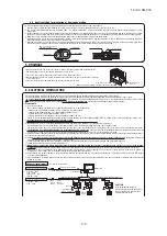
FDC121, 140, 155KXZES1 model
a) Exchange the PCB
after elapsing 3 minutes from power OFF
.
(
Be sure to measure voltage (DC)
on both capacitor terminals located in control back, and
check that the
voltage is discharged sufficiently
.(Refer to Fig.2))
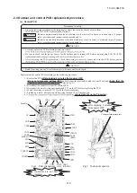
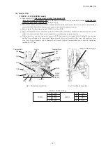
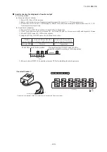
b) Take off the connection of inverter PCB terminal block connector and remove the screw of power transistor then
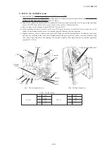
c) Refer to table1 for the setting of switch (JSW10,11) of new PCB.
d)
surface of power transistor. Make sure it is applied to prevent damage on power transistor.
e) Tighten the screw of power transistor on inverter PCB and connect the terminal block. Confirm the connection
and don’t use soldering in the connection. Tighten properly the power transistor with a screw and make sure there
is no slack. Power transistor can be damage if not properly tighten.(Recommended power transistor tightening
torque:0.98-1.47N∙m)
Parts No.
Fig.1 Parts arrangement view
Fig.2 Position of capacitor
TB5
TB6
CNI2
Connector
CNR
TB7
TB8
TB9
Voltage measurement parts
Switch
JSW11
JSW10
CNW2
Terminal
block
CNO1
CNW1
-1
OFF
-1
OFF
-2
OFF
-2
ON
-3
OFF
-3
OFF
JSW10
-4
OFF
JSW11
-4
ON
Table. 1 Switch setting
■
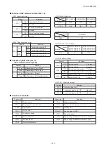
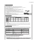
Function of DIP switch for contol (SW3, 4, 5)
• SW3 (Function setting)
Switch
Function
SW3-1
ON
Inspection LED reset
OFF
Normal
SW3-5
ON
Check operation start
OFF
Normal
SW3-7
ON
Forced cooling/heating
OFF
Normal
• SW4 (Change demand ratio)
Switch
Function
SW4-7
ON
SW4-8
OFF Compressor capacity
60
ON Compressor capacity
0
OFF
OFF Compressor capacity
80
ON Compressor capacity
40
■
Function of jumper wire (J13, 15)
(With: Shorted / None: Opened)
Jumper
Function
J13
With
External input Level input
None
External input Pulse input
J15
With
Defrost time Normal
None
Defrost time Cold weather region
■
Function of connector
• SW4 (Model selection)
Model
Switch
FDC121KXZE1 FDC140KXZE1 FDC155KXZE1
SW4-1
OFF
ON
OFF
SW4-2
OFF
OFF
ON
• SW4 (Overseas)
Model
Switch
All models
SW4-3
ON
• SW4 (Power source voltage)
Model
Switch
FDC121KXZEN1
FDC140KXZEN1
FDC155KXZEN1
FDC121KXZES1
FDC140KXZES1
FDC155KXZES1
SW4-4
ON
OFF
• SW5 (Function setting)
Switch
Function
SW5-1
ON
Test run switch
Test run
OFF Test run switch
Normal
SW5-2
ON
Test run operation mode
Cooling
OFF Test run operation mode
Heating
SW5-3
ON
Pump down switch
Pump down
OFF Pump down switch
Normal
• SW7, 8, 9 (Function setting)
Switch
Function
SW7
Data erase/data write
SW8
7-segment dispalay No. UP
order of 1
SW9
7-segment dispalay No. UP
order of 10
Connector
Function
Connector
Function
CNA1
Power source
CNL1
High pressure sensor
CNQ1
High pressure switch (CN1)
CNP1
Power transistor temperature sensor
CNW
Open phase
CNEEV1
Heating EEV
CNN1
4-way valve
CNEEV2
Sub-cooling coil EEV
CNR1
Crankcase heater
CNX1
Superlink signal
CNA2
Power fan motor
CNF1
Sub-cooling coil temperature sensor (liquid)
CNS1
External input
CNF2
Sub-cooling coil temperature sensor (gas)
CNL2
Low pressure sensor
Summary of Contents for FDC121KXZEN1
Page 159: ... 158 19 KX SM 318 ...
Page 161: ... 160 19 KX SM 318 ...
Page 162: ... 161 19 KX SM 318 ...

