–
126
–
'19 • KX-SM-318
●
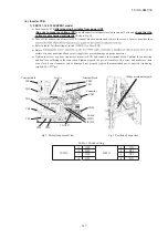
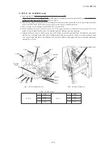
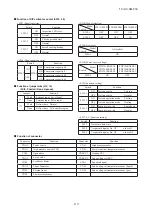
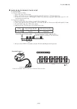
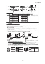
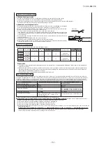
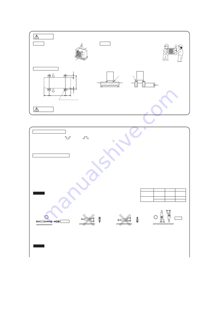
Please avoid forming any trap ( ) or bump ( ) in piping as they can cause fluid stagnation.
190
200
580
20
410
20
Wooden pallet
Patch plate
Air inlet
Air outlet
Anchor bolt position
(4 locations)
Fasten with bolts
(M10-12)
Use a long block to extend the width.
Use a thicker block to
anchor deeper.
Heavy
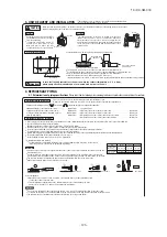
3. UNIT DELIVERY AND INSTALLATION
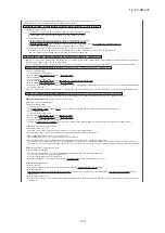
When you sling the unit for portage, do not fail to take into consideration the deviation of the gravity center from its center.
Improper slinging may cause the unit to lose balance and fall.
CAUTION
Important
●
The protrusion of an anchor bolt on the front side must be kept within 15 mm.
●
Securely install the unit so that it does not fall over during earthquakes or strong winds, etc.
●
Refer to the above illustrations for information regarding concrete foundations.
●
Install the unit in a level area. (With a gradient of 5 mm or less.)
Improper installation can result in a compressor failure, broken piping within the unit and abnormal noise generation.
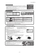
4. REFRIGERANT PIPING
4-1. Determination of piping specifications
(Please select from the following matrix according to indoor unit specifications and installation site conditions)
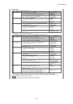
Refrigerant piping restrictions
Please do not fail to observe the following pipe sizes and limitations of use.
A failure to observe this instruction can result in a compressor failure or performance degradation.
Refrigerant piping size selection
Attention
●
Please use pipes of the pipe size specified for the outdoor unit for the section between the outdoor unit and the
first branching joint.
●
An appropriate pipe size between branching joints can vary depending on the connected indoor unit capacity
(total capacity connected downstream), please select an appropriate pipe size from the table shown on the right.
●
The pipe size between the branch pipe and the indoor unit should match that of the indoor unit.
●
Always install branch pipes either horizontally or vertically.
(1) Individual flow division method
●
For determination of appropriate branching joint or different diameter pipe joint sizes, please refer to
"Branching Pipe Set," (which can be purchased separately).
Attention
(2) Header Method
●
Depending on the number of units connected, connect blind pipes to header branching points
(on the indoor unit connection side).
●
For determination of appropriate header, different diameter pipe joint and blind pipe sizes,
please refer to "Header Set," (which can be purchased separately).
●
For the section between an indoor unit and the header, use a pipe of the diameter specified for the indoor unit.
●
To couple with the header, use a different diameter pipe joint to adjust to the pipe diameter specified for the indoor unit.
●
The header must be so installed that it branches horizontally. (for both gas and liquid)
Item
Outdoor unit
Main pipe
Total capacity of
indoor units
Model
121, 140, 155
less than 70
70 or more
Gas pipe
φ
15.88
φ
12.7
φ
15.88
Liquid pipe
φ
9.52
φ
9.52
φ
9.52
●
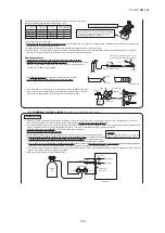
Please use pipes clean on both the inside and outside and free from contaminants harmful to operation such as sulfur, oxides, dust, chips, oil, fat and water.
●
Use the following material for refrigerant piping.
Material: phosphorus deoxidized seamless copper pipe (C1120T-0, JIS H 3300)
●
Thickness and size: Please select proper pipes according to the pipe size selection guideline.
(Since this unit uses R410A, Select pipes having a wall thickness larger than the specified minimum pipe thickness.
●
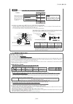
For branching pipes, use a genuine branching pipe set or header set at all times.
●
Install a branching pipe set, paying attention to the direction of attachment, after you have perused through the installation manual supplied with it.
●
The length of piping from outdoor unit to first branch is 1.5m or more.
●
For the handling of service valves, please refer to 4-2. Piping work.
Bolt fastening positions
In case that the unit operates in cooling mode, when the outdoor temperature is –5°C or lower,
please equip a flex flow adapter and a snow guard hood (option) on the unit.
Delivery
Portage
●
In installing the unit, fix the unit's legs with bolts specified below.
●
The right hand side of the unit as viewed from the front
(diffuser side) is heavier. A person carrying the right hand
side must take heed of this fact. A person carrying the left
hand side must hold with his right hand the handle provided
on the front panel of the unit and with his left hand the corner
column section.
●
Deliver the unit as close as possible to
the installation site before removing it
from the packaging.
●
If unpacked and deliver cannot be
avoided, use a nylon sling or a rope
with pads placed where the rope
contacts the unit so it is not scratched.
●
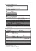
Maximum length (To the farthest indoor unit)
……………
Within 70m
●
Equivalent length (To the farthest indoor unit)
……………
Within 95m
●
Total pipe length (Combined total length of pipes)
………
Within 100m
●
φ
9.52 pipe length
………………………………………
Within 50m
●
Height difference
(1) When the outdoor unit is above the indoor unit
…………………………
Within 30m
(2) When the outdoor unit is below the indoor unit
…………………………
Within 15m
(3) Height difference between indoor units in the same system
……………
Within 15m
(4) Height difference between indoor units and first branch
…………………
Within 15m
Take particular care in carrying in or moving the unit, and always perform
such an operation with two or more persons.
(
)
Horizontal
Floor surface
Floor surface
Floor surface
Vertical
Floor surface
Summary of Contents for FDC121KXZEN1
Page 159: ... 158 19 KX SM 318 ...
Page 161: ... 160 19 KX SM 318 ...
Page 162: ... 161 19 KX SM 318 ...


