–
137
–
‘19 • KX-SM-318
●
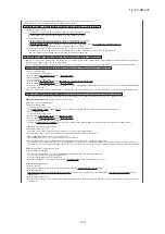
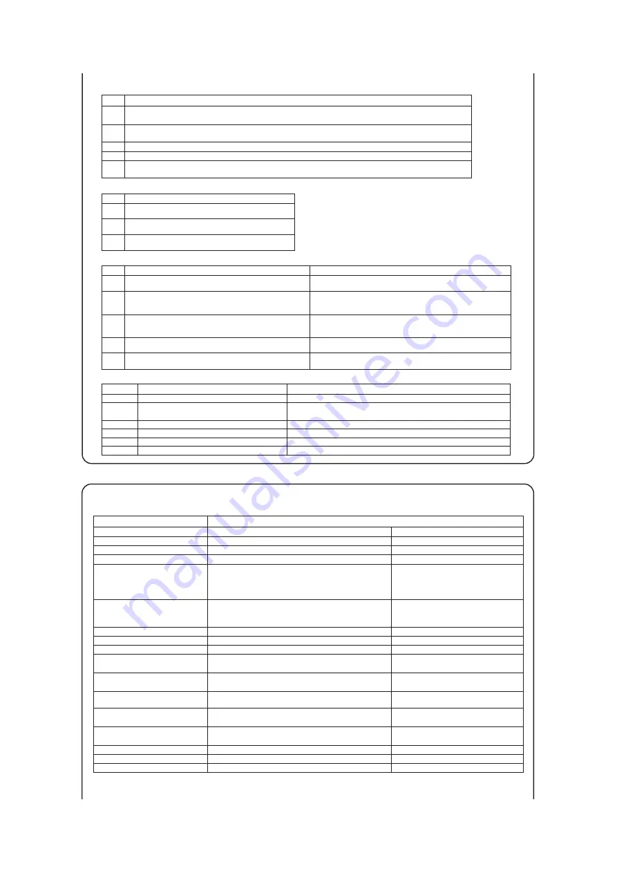
7-segment display indication in automatic address setting
Code
Contents of a display
P30
P31
P32
P34
Code
Contents of a display
Unable to find any indoor unit that can be actually communicated with.
The number of the indoor units that can be actually communicated with is
less than the number specified in P33 on the 7-segment display panel.
The number of the indoor units that can be actually communicated with is
more than the number specified in P33 on the 7-segment display panel.
Starting address (P32) + Number of connected indoor units (P33) > 128
While some units are operating in the previous SL mode on the network,
the automatic address setting on multiple refrigerant systems is attempted.
Are signal lines connected properly without any loose connections?
Is power for indoor units all turned on?
Are signal lines connected properly without any loose connections?
Are the network connectors coupled properly?
Input the number of connected indoor units again.
Are signal lines connected properly without any loose connections?
Are the network connectors coupled properly?
Input the number of connected indoor units again.
Input the starting address again.
Input the number of connected indoor units again.
Perform manual address setting.
Arrange all units to operate in the new SL.
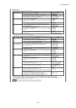
Code
A00
A01
A02
A03
A04
Contents of a display
Please check
Contents of a display
Cause
Code
E2
E3
E11
E12
E31
E46
Duplicating indoor unit address.
Incorrect pairing of indoor-outdoor units.
Incorrect adderess setting of indoor units.
Address setting for plural remote controls.
Incorrect setting.
Duplicating outdoor unit address.
・
Incorrect manual address setting
・
Indoor unit address is set from plural remote controls.
・
Plural outdoor units are exist as same address in same network.
・
Automatic address setting and manual address setting are mixed.
・
Automatic address setting and manual address setting are mixed.
・
An outdoor unit number that does not exist in the network is specified
・
No master unit exists in combination outdoor unit.
Items that are to be set by the customer
Communication protocol
1: New SL mode
0: previos SL mode
Polarity difinition
0: Network polarity not defined.
1: Network polarity defined.
AUX
During automatic address setting.
X: The number of indoor units recognized by the outdoor unit.
AUE
Indoor unit address setting is completed normally.
End
Polarity is defined. (Automatic address)
Completed normally.
Automatic address start
Input starting address
Specify a starting indoor unit address in automatic address setting.
(The communication plotocol is displayed ; display only)
P33
Input number of connected indoor units
Specify the number of indoor units connected in the refrigerant system in automatic address setting.
0: Automatic address standby
1: Automatic address start
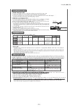
7-segment display indication in automatic address setting.
( )
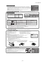
Outdoor unit control settings can be changed with the dipswitch and 7-segment display P
○○
setting on the PCB
.
In changing settings in P
○○
on the 7-segment display
panel, you can use SW8 (increasing a number shown on the 7-segment display panel: one’s place), SW9 (increasing a number shown on the 7-segment display panel: tens
place) and SW7 (data write/enter) by pressing them for a prolonged time.
*1 The switching is activated when both SW and P
○○
are changed.
*2 The switching is activated when a signal is input to CnS1.
*3 Capacity restriction is effected without a signal input to CnS1 in the capacity save mode.
SW5-5 ON: previous SL communication, OFF: new SL communication
J13: closed (factory setting) for level input, J13: opened for pulse input
J15: closed (factory setting) for normal defrost, J15: opened for enhanced defrost
DIP switch SW setting
P
○○
setting on the 7-segment display panel.
Select “2” in P07. *1
ー
ー
ー
Select “1” in P07. *1
ー
ー
ー
Forced cooling/heating mode*2
Cooling test operation
Heating test operation
Pump down
Switch SW3-7 to ON
※
1
Switch SW5-1 to ON + SW5-2 to ON
Switch SW5-1 to ON + SW5-2 to OFF
SW4-7:OFF, SW4-8:OFF
※
1
80% (
factory setting)
SW4-7:ON , SW4-8:OFF
※
1
60%
SW4-7:OFF, SW4-8:ON
※
1
40%
SW4-7:ON , SW4-8:ON
※
1
00%
Demand mode *2
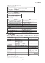
7-2. CONTROL SWITCHING
ー
ー
ー
ー
ー
ー
ー
ー
30sec (factory setting
)
10
,
30
-
600sec
0: invalid (factory setting)
1: valid
Communication protocol setting
CnS1 input setting
Defrost setting
Operation priority change
Outdoor fan snow guard control
Outdoor fan snow guard control
operation time setting
Capacity save mode *3
Silent mode setting *2
External output (CnZ1) function assignment
External input (CnS1) function assignment
Spare
Contents of Control switching
Method of control setting
Close the outdoor unit service valves and perform
the following operations in the stated order:
(1) Switch SW5-2 to ON
(2) Switch SW5-3 to ON
(3) Switch SW5-1 to ON
OFF: invalid (factory setting)
000, 040, 060, 080 [%]
0: earlier entry priority (factory setting)
1: later entry priority
J13 closed: level input
J13 opened: pulse input
P02
P03
P04
P05
P06
P07
P8
-
29
P01
0 (factory setting) – 3: the larger the number,
the stronger the effect.
Address setting failure indication
Error indication
Summary of Contents for FDC121KXZEN1
Page 159: ... 158 19 KX SM 318 ...
Page 161: ... 160 19 KX SM 318 ...
Page 162: ... 161 19 KX SM 318 ...

