–
140
–
'19 • KX-SM-318
Precau
tions for s
a
fety
Read
th
e
se "
Precau
tions for s
a
f
e
ty" c
are
f
ull
y b
e
fo
re
st
ar
tin
g
d
i
s
a
ssemb
l
y wor
k
a
nd do
i
t in th
e
pro
pe
r way
.
W
h
e
n d
i
s
a
ssemb
li
n
g,
b
e
sur
e
to t
u
rn off th
e
p
ow
e
r. Wh
e
n d
i
sass
e
mb
li
n
g
th
e
elec
trica
l
c
om
p
on
e
nts,
c
h
ec
k th
e
elec
trica
l
wirin
g
di
agra
m.
T
h
e
elec
tr
ical
c
om
p
on
e
nts
are
u
n
de
r h
ig
h vo
l
ta
ge
by th
e
o
pera
tion of th
e
boost
e
r
capaci
tor.
Full
y
di
sch
arge
th
e
capaci
tor b
e
for
e
c
omm
e
n
ci
n
g
a r
epai
r wor
k.
Fa
ilure
to obs
e
rv
e
th
i
s w
ar
n
i
n
g
c
o
ul
d r
e
su
l
t
i
n
elec
tri
c
sho
ck.
W
h
e
n parts of r
e
f
rigera
nt
c
y
cle
i
s d
i
s
a
ssemb
led
by w
eldi
n
g,
b
e
sur
e
to wo
rk
aft
e
r co
llec
tin
g
a r
e
f
rigera
nt
,
i
f th
e
r
e
f
rigera
nt
i
sn
'
t
c
o
llec
t
ed,
th
e
u
n
i
t m
ig
ht
expl
o
de.
Be
sur
e
to
c
o
llec
t r
e
f
rigera
nt w
i
thout spr
eadi
n
g
i
t
i
n th
e
a
ir.
T
h
e
se
c
ont
e
nts
are
an
exa
m
ple.
Pl
eas
e
r
e
f
e
r to
a
s
i
m
il
ar
pa
rt of
ac
t
ual
u
n
i
t.
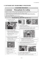
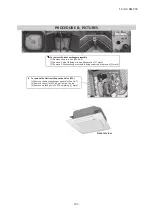
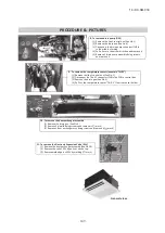
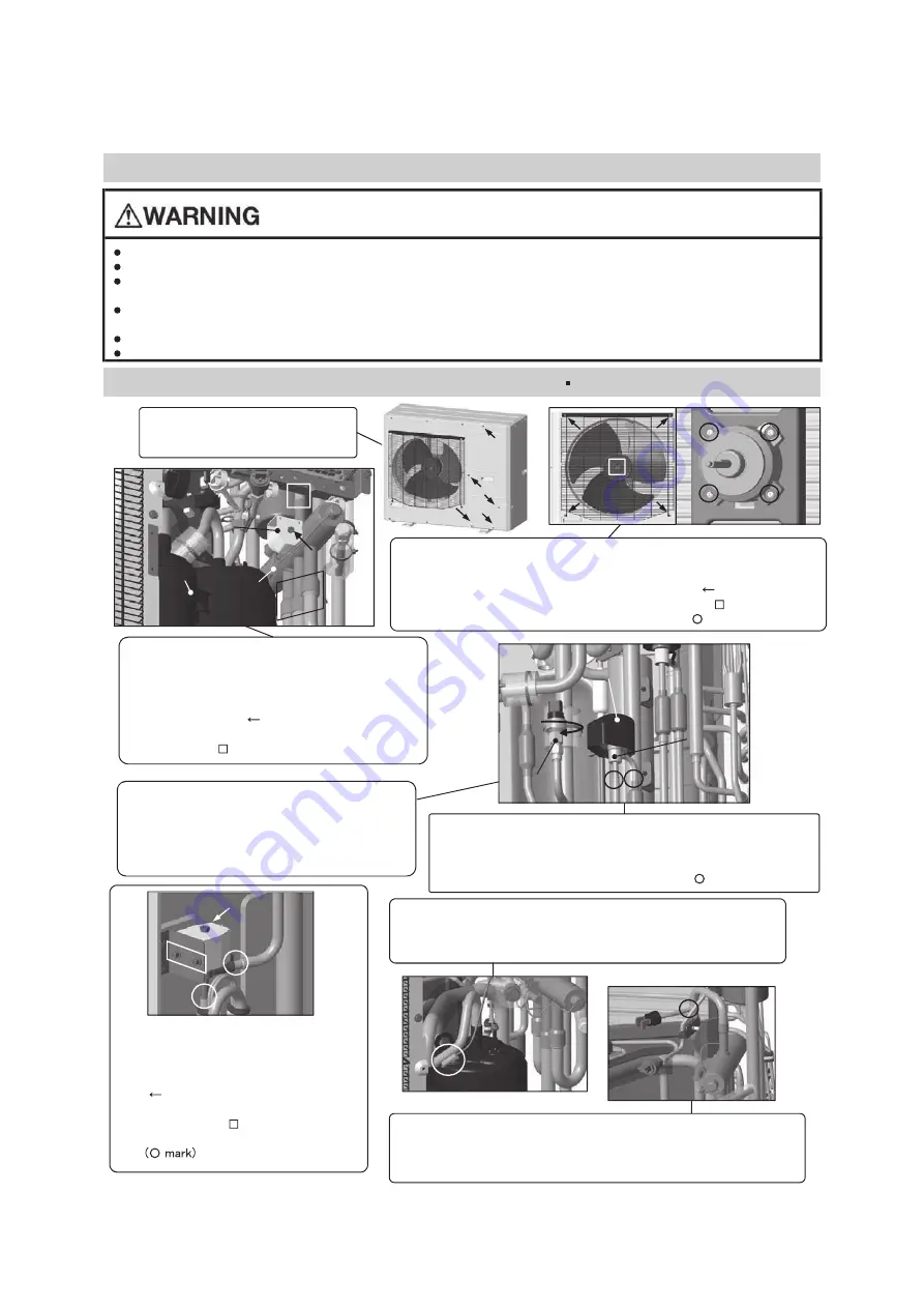
1. T
o remov
e
the s
e
rv
ice
p
a
n
el
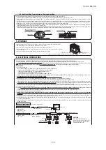
(1) Remove 5 service pa
nel fi
screws and remove it.
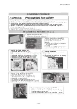
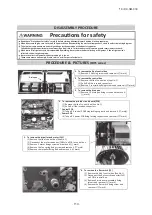
2. T
o remov
e
the f
a
n moto
r
(F
M)
(1) Remove the service panel.(See No.1)
(2) Disconnect the motor connector(FMxx or CNFxx) on PCB in control box.
(3) Remove 4 fan guard
fixing scr
ews and remove it.( mark)
(4) Remove the propeller fan
fixing
nut and remove it.( mark)
(5) Remove 4 fan motor
fixing
nuts and remove it.( mark)
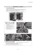
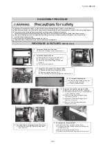
3. T
o remov
e
the 4
-
w
a
y va
l
ve (
20S)
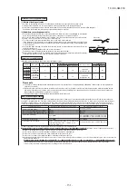
(1) Remove the service panel.(See No.1)
(2) Disconnect the coil of 4-way valve connector
(CNNx or CNS,CN20S) on PCB in control box.
(3) Remove the coil of 4-way valv
e fi
xing screw
and remove it.( mark)
(4) Remove welded part of 4-way valve by
welding. ( mark)
4
. T
o remov
e
the
l
ow
pre
ssu
r
e s
e
nsor (
PSL)
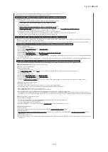
(1) Remove the service panel.(See No.1)
(2) Disconnect the PSL connector(CNLx or CNPS)
5. T
o remov
e
the
el
ect
r
onic
expa
ns
i
on va
l
ve (
EEV)
)
1
.
o
N
e
e
S
(.
l
e
n
a
p
e
c
i
v
r
e
s
e
h
t
e
v
o
m
e
R
)
1
(
.
x
o
b
l
o
r
t
n
o
c
n
i
B
C
P
n
o
(3) Turn PSL to the le
ft
and remove it.
(2) Disconnect the EEV connector(CNEEVx) on PCB in control box.
(Double spanners are needed.)
(3) Remove the coil of EEV by pull out on the top.
(4) Remove welded part of EEV by welding.( mark)
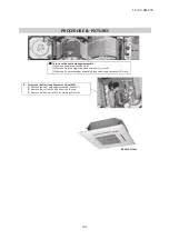
6. T
o remov
e
the temperature sensors (
exa
m
ple
"
T
ho
-D1
")
(1) Remove the service panel.(See No.1)
(2) Disconnect the Tho-D1 connector(CNTH) on PCB in control box.
(3) Pull out the temperature sensors "Tho-D1" from the sensor holder.
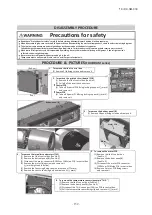
7. T
o remov
e
by
pa
ss v
al
ve (
SV)
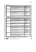
(1) Remove the service panel.(See No.1)
(2) Disconnect the SV connector
on PCB in control box.
(3) Remove the coil of SV
fixing scr
ews.
( mark)
(4) Remove 2 c
oil of SV fi
xing screws
and remove it.( mark)
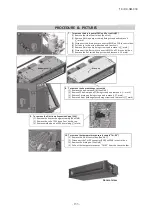
8. T
o remov
e
the high
pre
ssur
e
swit
c
h (
63H)
(5) Remove welded part of SV by welding.
(1) Remove the service panel.(See No.1)
(2) Disconnect the 63H connector(CNH or CNQx) on PCB in control box.
(3) Remove welded part of high pressure switch by welding.
DISASSEMBLY
PROCEDURE
PROCEDURE
&
PICTURE
S
(FDC
SCM
s
erie
s)
C
om
pre
sso
r
4
-
w
a
y v
al
v
e
C
o
il
of 4
-
w
a
y valv
e
EEV
C
o
il
of
EEV
PSL
6
.
OUTDOOR UNIT DISASSEMBLY PROCEDURE
6. OUTDOOR UNIT DISASSEMBLY PROCEDURE
Summary of Contents for FDC121KXZEN1
Page 159: ... 158 19 KX SM 318 ...
Page 161: ... 160 19 KX SM 318 ...
Page 162: ... 161 19 KX SM 318 ...

