–
49
–
‘19 • KX-SM-318
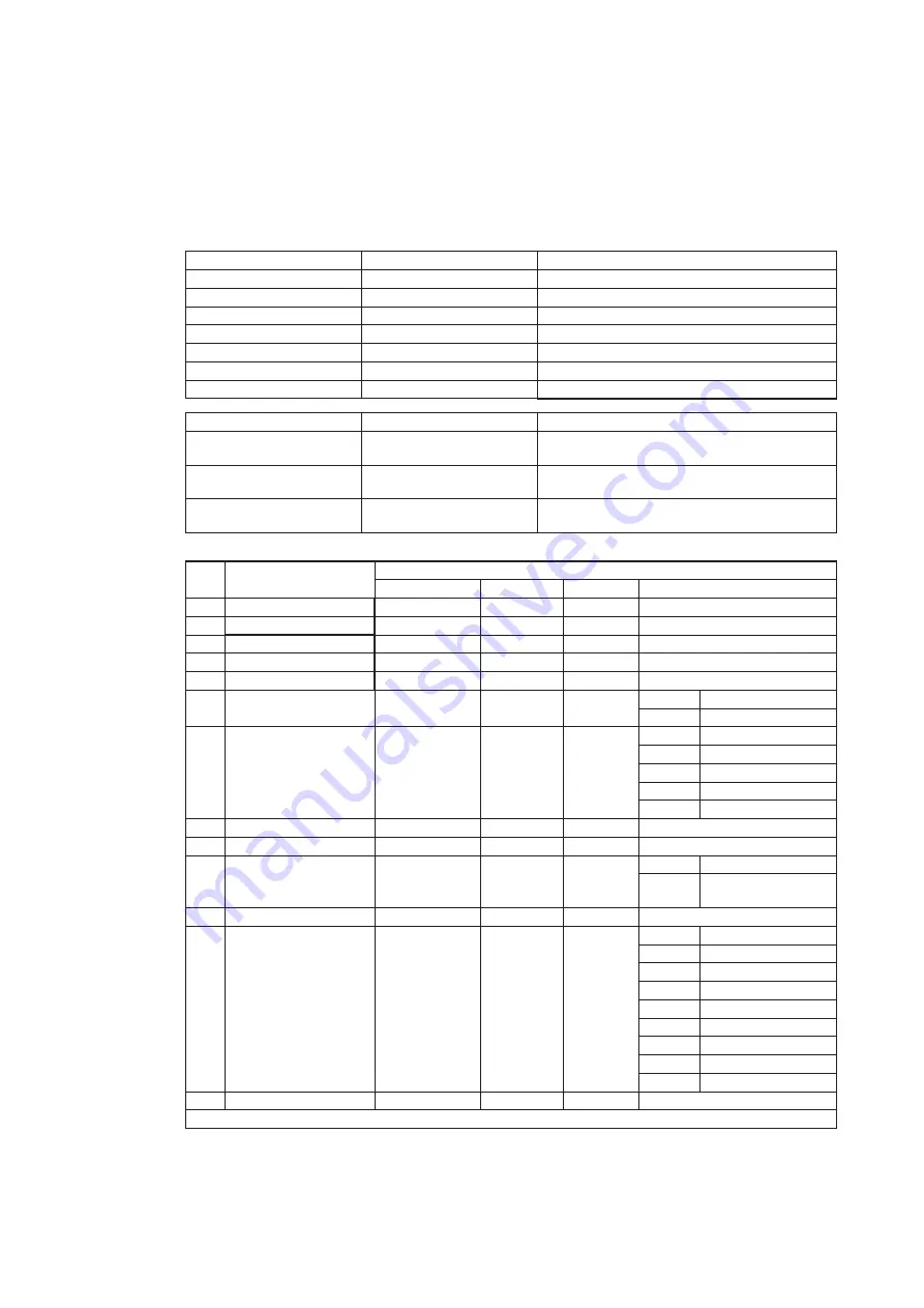
Code
No.
Contents of data display
Data display range Minimum
unit
Remarks
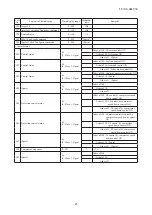
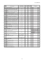
<New Superlink setting>
P30
Superlink communication
satus
0,1
–
0: Current Superlink
1: New Superlink
P31 Start automatic address setting
0 : (Factory default)
0,1
–
0: Automatic address setting standby.
1: Automatic address setting start.
P32 Input starting indoor address
1 : (Factory default)
0 - 127
1
Specify the starting indoor address connected in one
refrigerant system for automatic address setting.
P33
Input the number of connected
indoor unis
1 : (Factory default)
1 - 24 (*)
1
Specify the number of indoor units connected in one
refrigerant system for automatic address setting.
(*) Maximum connectable number of indoor units for each
oudoor unit
P34 Polarity difinition
0 : (Factory default)
0,1
–
0: Network polarity not defined
1: Network polarity defined
P35
Indoor address clear
transmission 2
0 : (Factory default)
0,1
–
0: Does not transmit clear setting signal
1: Transmits clear setting signal (* Interlocked with [P34].)
For operation error protection
P36 (Spare)
–
P37 (Spare)
–
P38 (Spare)
P39 (Spare)
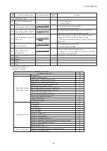
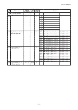
*1 Compressor stop cause
It shows the latest comprressor anomalous stop cause
Compressor stop cause
No.
At power on
0
Sensor disconnection
and/or short-circuit
Ambient air temperature
1
Outdoor heat exchanger temperture 1
2
Outdoor heat exchanger temperture 2
3
Discharge pipe temperature sensor (CM1)
4
Suction pipe temperature sensor
5
Sub-cooling temperature sensor (liquid side)
6
Sub-cooling temperature sensor (gas side)
7
Under-dome temperature sensor
8
Power transistor temperature sensor
9
Active filter temperature sensor
10
High pressure sensor
11
Low pressure sensor
12
Anomaly detection
HP anomaly
20
LP anomaly
21
Td1 anomaly
22
FMo1 anomaly
23
FMo2 anomaly
24
Inverter 1 current cut
25
Inverter 1 startup failure
26
Inverter 1 communication error
27
Inverter 1 anomalous compressor induced voltage and torque
28
Inverter 1 power tansistor overheat
29
Inverter 1 rotor lock
30
Liquid flooding anomaly
31
Stop by restriction
Outdoor operation mode heating/cooling switching
40
Heating overload protection
41
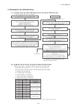
(c) Saving of operation data
Mainly for investigating causes of market claims, operation data are always saved in memory. If any trouble occurs, the
data writing is stopped and only the operation data prior to the time when the trouble occurs are recorded. These data can
be loaded to a PC via RS-232C connector of PCB and utilized for identifying causes.
(i) Operation data for a period of 30 minutes prior to the present operation are saved and updated continuously.
(ii) If an anomalous stop occurs, the data are not updated any more.
(iii) Data are written in based on 1 minute sampling interval and next data will be transmitted to PC upon demand.
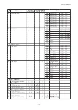
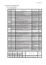
Data
Data range
Example
Software version
Ascii 15 bytes
KD3C218######## (# : NULL)
PID (Program ID)
Ascii 2 bytes
5D
Outdoor unit capacity
Ascii 3 bytes
As listed blow
Power source frequency
Ascii 2 bytes
60
Outdoor address
Ascii 2 bytes
00 - 3F
Indoor address × 16 units
Ascii 2 bytes × 16 units
40 - 7F
Indoor capacity × 16 units
Ascii 3 bytes × 16 units
022 - 280
Outdoor unit composition
Outdoor unit capacity data
Remarks
Single type
Example: 24HP - [S24]
S: Display with Horse Power of single type or
single use of combination type
Master unit of combination
type
Example: 46HP - [S46]
S: Display with Horse Power of master unit of
combination type
Slave unit of combination
type
Example: 20HP - [C20]
C: Display with Horse Power of slave unit of
combination type
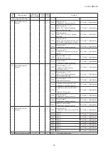
(iv) Error retention and monitoring data
Code
No.
Write contents
Record data
Data write range Unit of write Number of bytes
Contents
0
Indoor 1 Thi-A
–14 - 50
A/D value
1
Suction
1
Indoor 1 Thi-R1
0 - 72
A/D value
1
Heat exchanger 1
2
Indoor 1 Thi-R2
0 - 72
A/D value
1
Heat exchanger 2
3
Indoor 1 Thi-R3
0 - 72
A/D value
1
Heat exchanger 3
4
Indoor 1 EEV
0 - 470
1 pulse
2
5
Indoor 1 operation/stop
0,1
–
1
0
Stop
1
Operation
6
Indoor 1 operation mode
0 - 4
–
1
0
Auto
1
Dehumidifying
2
Cooling
3
Fan
4
Heating
7
Indoor 1 request Hz
0 - 255
1Hz
1
8
Indoor 1 answer Hz
0 - 255
1Hz
1
9
Indoor 1 indoor local
–
–
1
Bit0
Anti-frost
Bit1
EEV opening angle
implementation
10 Indoor 1 Thi spare
–14 - 50
A/D value
1
Discharge
11 Indoor 1 type
0 - 8
–
1
0
FDT
1
FDK
2
Others
3
FDE
4
FDTC
5
6
7
60 -
12 Indoor 1PID
–
–
1
The data of indoor unit No.2-16 are continued. (contents are same as above)
Summary of Contents for FDC121KXZEN1
Page 159: ... 158 19 KX SM 318 ...
Page 161: ... 160 19 KX SM 318 ...
Page 162: ... 161 19 KX SM 318 ...

