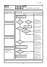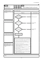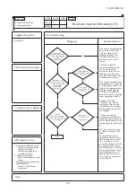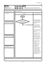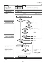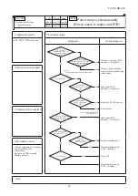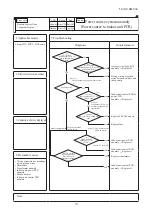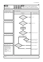
–
60
–
'19 • KX-SM-318
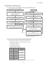
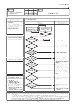
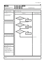
2.2 Explanation of troubleshooting
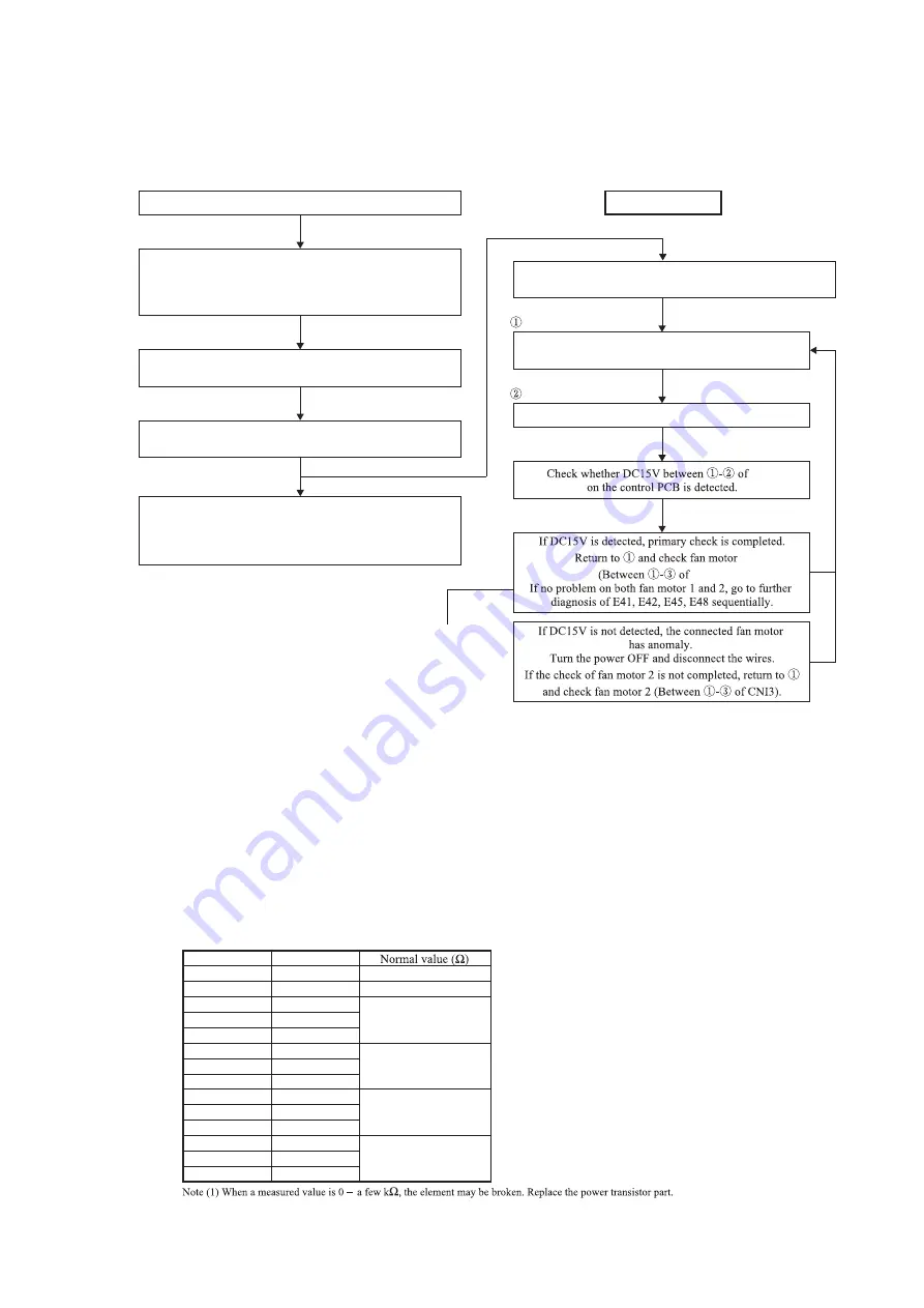
(a) Checking 15V on the control PCB (Step to check if the inverter PCB fails or not)
Use this to diagnose E41, E42, E45 and E48.
(b) Inspection of short-circuit on the power transistor module terminals
Disconnect the wiring of compressor and check for short-circuit with a tester.
Inspect between terminals of: P-U, P-V, P-W, N-U, N-V, N-W and P-N
It will be easier to contact the tester at the following place at each terminal.
P: P terminal of power transistor
N: N terminal of power transistor
U: End of red harness to compressor
V: End of white harness to compressor
W: End of blue harness to compressor
Power OFF (Power source circuit breaker OFF)
Fan motor check
Even if DC15V is detected, affection by fan motor anomaly is
suspected. Implement following check.
*Be sure to check both fan motor 1 and 2
*After completion of checking both fan motor 1 and 2,
replace the anomalous fan motor.
Turn the power ON (Power circuit breaker ON)
and start operation with the test run switch.
Check between #1 and #2 of CnA2 on the control
PCB to see if DC 15V is detected.
Be sure to wait for 3 minutes after turning the
power circuit breaker off.
Disconnect the fan motor wires.
(Both the power cable and control wires)
Turn the power circuit breaker OFF.
Wait 3 minutes.
Check
E41, 42, 45, 48
Connect the wires of fan motor 1 or 2.
Power ON
Test run switch ON
Since, unless DC15V is detected, faulty inverter PCB is suspected,
check CnI at the control PCB side, the connector connection of
CnA at the inverter side and breakage of communication wires.
If everything is all right, replace the inverter PCB.
③
Terminal (+)
P
N
P
P
P
N
N
N
U
V
W
U
V
W
Terminal (-)
N
P
U
V
W
U
V
W
P
P
P
N
N
N
Several 10 M
Several 10 M
Several 10 M
Several 100K
Several 100K
Several M
CnA2
CnI3).
2.2 Explanation of troubleshooting
Summary of Contents for FDC121KXZEN1
Page 159: ... 158 19 KX SM 318 ...
Page 161: ... 160 19 KX SM 318 ...
Page 162: ... 161 19 KX SM 318 ...


