background image

– 

128

 –

 '18 • KX-SM-292

20

Out door unit

Height  difference 
between  indoor 
units:  18 m thicker 

Height difference 

 50 m

Actual length    

160 m

Equivalent length  

185 m

Total piping length   510 m

Indoor unit

Suction

Blowout

195

195

690

Foundation  bolt  position
  (4  places)

20

520

20


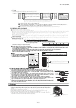
The protrusion of an anchor bolt on the front side must be 

kept within 15 mm.


Securely install the unit so that it does not fall over during 

earthquakes or strong winds, etc.


Refer to the above illustrations for information regarding 

concrete foundations.


Install the unit in a level area. (With a gradient of 5 mm or 

less.)


Improper installation can result in a compressor failure, broken 

piping within the unit and abnormal noise generation.

Wooden  base

Wear  plate

fig

Indoor unit

Indoor unit

Outdoor unit

Branch pipe set for indoor unit side

Model: DIS

Branch pipe set for indoor unit side

Model: DIS

Header set for indoor unit side

Model: HEAD

A

B

B

C

C

B

B

C

C

C

C

C

C

Accessory

Caution

Be sure to read this manual before installation to follow the proper installation methods.

When installing the indoor unit, read the installation manual of indoor unit.

Option distribution parts are required for the piping (Branch pipe set, header set). For details, refer to the catalog, etc.

Make sure to install the earth leakage breaker. (Select a product compatible with high frequency.)

There is risk of damaging the compressor if the unit is operated while the discharge pipe temperature sensor, suction pipe temperature sensor, pressure sensor, etc. are removed.  

Never attempt to operation in such condition.

With this air-conditioning system, room temperature may rise, depending on installation conditions, while indoor units are stopped, because small quantity of refrigerant flows into 

the stopped indoor units if heating operation is conducted on the system.

Combination pattern

Combination pattern of outdoor units, number of indoor units connected and capacity of connection are as show in the table at right.

It can be used in combination with the following indoor unit.

Name

Wire

Quantity

1

1

1

Location of use

Insert this in CnG on the outdoor unit PCB when using the silencing mode or 
forced cooling mode

Secured in the control box with adhesive tape.

It is attached to the bracket with an adhesive tape 
in the proximity of the service valve.

Attached on the base below the service valve.

Attached on the base below the service valve.

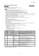
1. BEFORE BEGINNING INSTALLATION 

(Check that the models, power source specifications, piping, wiring are correct.)

3-1.  Delivery 

2. INSTALLATION LOCATION


(Obtain approval from the customer when selecting the installation area.)

2-1.  Selecting  the  installation  location

Deliver the unit in the packing to the specified installation place.

To hoist the unit, attach a pair of textile ropes with cushion materials attached to protect it.

Request

Put cushion materials between the unit and the ropes to avoid damages.

Attach the ropes on the unit and carry it in avoiding displacement of gravity center.

Improper slinging may cause the unit to lose balance and fall.

4. REFRIGERANT PIPING

3. Unit delivery and installation

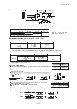
(1) Limitation on use of pipes

(3) Pipe size selection

Caution

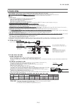
When arranging pipes, observe the restrictions on use concerning the longest distance of (1), total piping length, 

allowable pipe length from initial branching and allowable difference of height (difference between heads).

Maximum length (To the furthest indoor unit) … Actual length Less than 160 m (Actual length less 

than 185 m)

It is required to change the pipe diameter when the actual length exceeds 90 m.

Determine the size of main pipe, referring to the table of main pipe selection table of (3) (a).

Total piping length ………………………………………………………… 510 m or less

Length of main pipe ……………………………………………………… 130 m or less

Allowable pipe length from initial branching …………………………… 90 m or less

Difference in pipe lengths between indoor units, however, is 40 m or less.

Allowable difference in height (Difference of heads)

(a) When an indoor unit is positioned at a higher place ………………  50 m or less

(b) When an outdoor unit is positioned at a lower place ……………… 40 m or less

(c) Difference of heights between indoor units in a system …………… 18 m or less

(d) Difference of heights between initial branching and indoor unit … 18 m or less

(2) Selection of pipe material

Use pipes with the inside clean and free from any harmful sulfur, oxides, dirt, chips & oil, or moisture 

(contamination).

Use following refrigerant pipes.

Material … Phosphate deoxidation treated seamless pipe (C1220T-O, 1/2H, JIS H 3300)

C1220T-1/2H for O.D. ø19.05 or more, or C1220T-O for ø15.8 or less

Wall thickness and size - Select according to the guide for pipe size selection

(This product uses R410A. Since, in case of pipes in the size of ø19.05 or more, materials of -O 

thickness larger than the minimum thickness.)

When a pipe is branched, make sure to use our branching set or header set.

When setting branching pipes, take care of the mounting direction and consult carefully with the 

instruction manual.

Regarding the handling of service valve, refer to 4-3 (1) Operating method of service valve.

Make sure to lock the fixing legs of outdoor unit with 4 pieces of anchor bolt (M10). Best margin of protrusion for bolt above the 

floor is 20 mm.

 When installing the unit, make sure to lock its legs with the following bolts.

3-2.  Cautions  for  installation

CAUTION

Make sure to install within the range of limitation. Otherwise, resulting 

malfunction of compressor may not be warranted. Observe always the 

limitation of use during installation.

Over 500 mm

Fasten  with  anchor  bolts

Edging

Attached 

wire

Instruction manual

Use it for protection of a knock-out hole.

Use this when connecting gas pipe.

When the installation work is completed,
give instructions to the customer and ask him/her to keep it.

4-1

. Determination of piping specifications

 (Please select from the following matrix according to indoor unit specifications and installation site conditions.)

Lock  with  bolt  (M10-12)

Suction

Blowout

Use a long block to extend the width.

Use  a  thicker 
block  to  anchor 
deeper.

PSC012D119

This installation manual deals with outdoor units and general installation specifications only. For indoor units, please refer to the respective installation manuals supplied with your units.

Please read this manual carefully before you set to installation work and carry it out according to the instructions contained in this manual.

Outdoor unit capacity

FDC224

-

335

Notabilia as a unit designed for R410A

a

b

c

d

e

f

g

h

Gauge manifold
Charge hose
Electronic scale for refrigerant charging
Torque wrench
Flare tool
Protrusion control copper pipe gauge
Vacuum pump adapter
Gas leak detector

Dedicated R410A tools

Do not use any refrigerant other than R410A.  R410A will rise to pressure about 1.6 times higher than that of a conventional refrigerant.

A unit designed for R410A has adopted a different size outdoor unit service valve charge port and a different size check joint provided in the unit to 

prevent the charging of a wrong refrigerant by mistake.  The processed dimension of the flared part of a refrigerant pipe and a flare nut's parallel side 

measurement have also been altered to raise strength against pressure.  Accordingly, you are required to arrange dedicated R410A tools listed in the 

table on the right before installing or servicing this unit.

Do not use a charge cylinder.  The use of a charge cylinder will cause the refrigerant composition to change, which results in performance degradation.

In charging refrigerant, always take it out from a cylinder in the liquid phase.

All indoor units must be models designed exclusively for R410A.  Please check connectable indoor unit models in a catalog, etc.

(A wrong indoor unit, if connected into the system, will impair proper system operation)

Sample

Size

1

2

3

4

Open

300

300

250 (5)

Open

5

300

250 (5)

1500 (500)

Open

300

250 (5)

Air 

inlet

Air 

inlet

Air 

outlet

Service 

space

L

3

L

2

L

4

L

1

(Unit : mm)

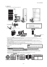
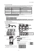
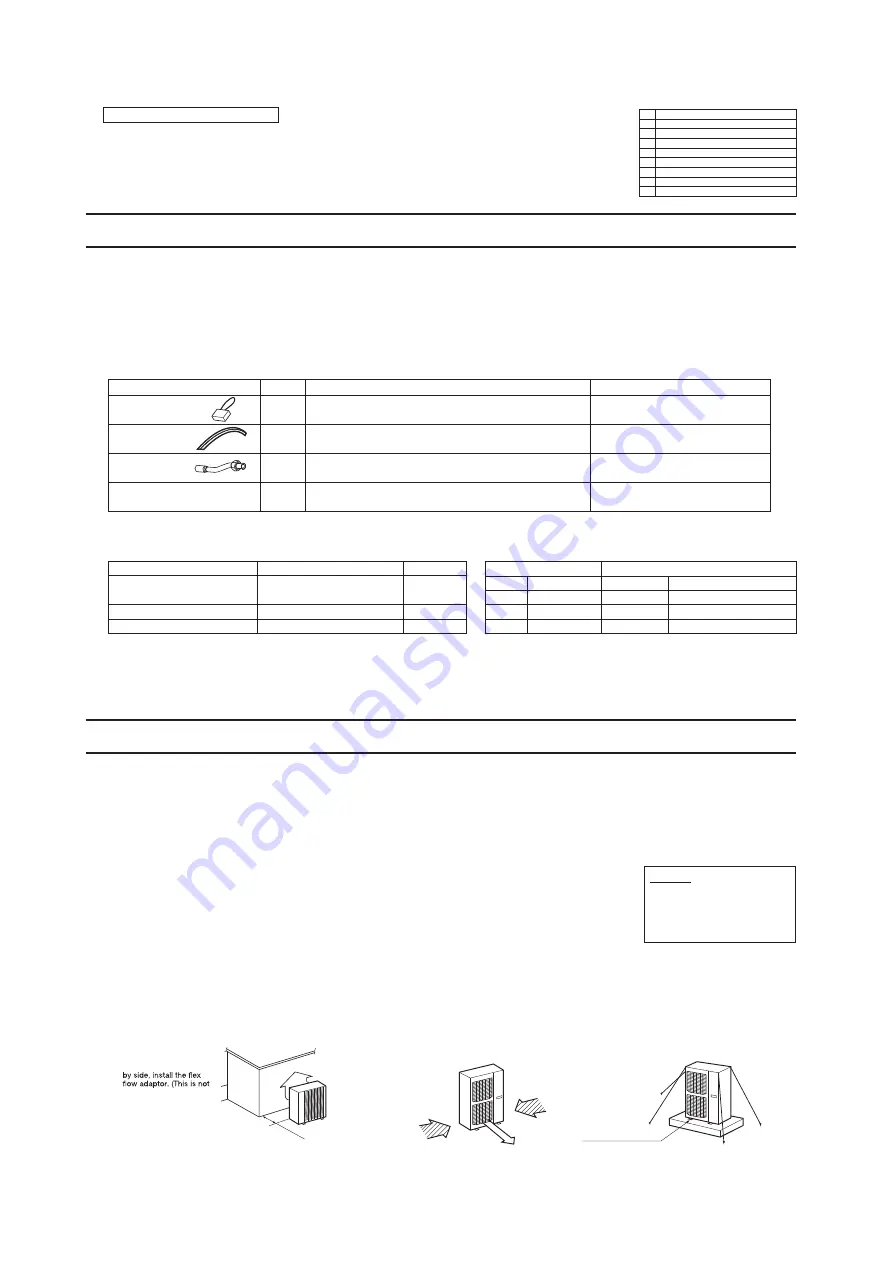
a) Minimum installation space 

(Please select an installation point with due attention to the direction of installation of the refrigerant pipe)

(If the installation conditions shown in this drawing are not satisfied, please consult with your dealer 

or the manufacturer.)

b) When two or more units are installed in a line, secure a service space of minimum 250 mm between 

each pair of neighboring units. The units can be operated, however, if they are separated by more 

than 10 mm each other. Where this minimum space is not available, it may be adapted by moving 

one of the units, for example, during the service work.

c) Don’t install at a place where it will be surrounded with walls in four directions.

Even when it is not surrounded with walls in four directions and it is met the installation conditions 

as shown by this figure, if there is risk of short-circuit, install the flex flow adaptor to prevent the 

short-circuit. 

d) There must be a 1-meter or larger space in the above.

e) A barrier wall placed in front of the exhaust diffuser must not be higher than the unit.

2-2.  Installation  space  (Ex.  servicing  space)

Floor surface

Floor surface

Floor surface

Liquid side

Horizontal

Floor surface

Floor surface

Gas side

Floor surface

Branching at 

downstream 

side

Important

In  case  that  the  unit  operates  in  cooling  mode,  when  the  outdoor  temperature  is  –5°C  or  lower, 

please  equip  a  flex  flow  adapter  and  a  snow  guard  hood  (option)  on  the  unit.

[Items sold separately]

Refrigerant pipe distribution parts, which are not contained in the package, will be required for installation.

As for refrigerant pipe distribution parts, we offer branching pipe sets (Model type: DIS) and header sets (Model type: HEAD) as parts used on the indoor side of piping.

Please select one suiting your application. In selecting distribution parts, please also refer to “4. REFRIGERANT PIPING.”

If you are not sure which parts to select, please consult with your dealer or the manufacture.

Use refrigerant branching pipe sets and header sets designed exclusively for R410A without fail.

Place the unit outlet pipe perpendicular 


to the wind direction.

Please install so the direction of the air from the blowing 


outlet will be perpendicular to the direction of the wind.

When the foundation is not level, use wires 


to tie down the unit.

 Where  air  is  not  trapped.

 Where  the  installation  fittings  can  be  firmly  installed.

 Where  any  object  does  not  prevent  inlet  or  outlet  air.

 Out of the heat range of other heat sources.

 Where  strong  winds  will  not  blow  against  the  outlet  air.

 A  place  where  stringent  regulation  of  electric  noises  is  applicable.

 Where  it  is  safe  for  the  drain  water  to  be  discharged.

 Where  noise  and  hot  air  will  not  bother  neighboring  residents.

 Where  snow  will  not  accumulate.

 A  place  where  no TV  set  or  radio  receiver  is  placed  within  5m. 

   (If  electrical  interference  is  caused,  seek  a  place  less  likely  to  cause  the  problem)

 Do not install the unit in places which exposed to sea breeze (e.g. coastal area) or calcium 

chloride  (e.g.  snow  melting  agent),  exposed  to  ammonia  substance  (e.g.  organic  fertilizer).

Please note

a) If there is a possibility of a short-circuit, then install a flex flow adapter.

b) When installing multiple units, provide sufficient intake space so that a short-circuit does not occur.

c) In areas where there is snowfall, install the unit in a frame or under a snow hood to prevent snow from accumulating on it. 

 (Inhibition of collective drain discharge in a snowy country)

d) Do not install the equipment in areas where there is a danger for potential explosive atmosphere.

e) Install the equipment in a location that can sufficiently support the weight of the equipment. 

f)


If a unit is installed into a special environment as shown below, there will be a danger that the corrosion of the outdoor unit or its 

malfunctioning is caused.  If this is the case, please consult with the distributor from whom you have purchased the unit.

  ・

Where corrosive gas is generated (such as a hot-spring resort area).

  ・

Where the unit is subject to sea breezes (coastal area).

  ・

Where the unit is subject to oil mists.

  ・

Where equipment generating electromagnetic waves exists in the vicinity.

g) When strong winds occur


Where it is likely that the unit is subjected to strong winds, provide wind guards according to the following guidelines.


Strong winds can cause performance degradation, an accidental stop due to a rise of high pressure and a broken fan.

CAUTION

Please  leave  sufficient  clearance 

around the unit without fail.

Otherwise,  a  risk  of  compressor 

and/or  electric  component  failure 

may arise.

When installing units side 

required if a distance of 

1,500 mm may be 

secured between the 

blowing outlet and the 

wall.)

Wind  direction

Wind  direction

Outdoor unit

224
280
335

Gas pipe

ø19.5×t1.0  
ø22.22×t1.0

ø25.4(ø22.22)×t1.0  

Liquid pipe

ø9.52×t0.8

ø12.7×t0.8

Gas pipe

ø22.22×t1.0

ø25.4(ø22.22)×t1.0

Liquid pipe

ø12.7×t0.80

Main pipe size (Ordinary)

Pipe size for actual length longer than 90 m

For ø19.05 or larger, use C1220T-1/2H material.

Make sure to use the attached pipes 
in the length as shown at left.

For ø19.05 or larger, use C1220T-1/2H material.
*1: When connecting indoor units of 280 at the downstream and the main gas pipe is of ø22.22 or larger, use the pipe of ø22.22x t1

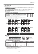
(a) Main pipe (Between branch at outdoor unit side - initial branch at indoor unit side): Section A in Fig. 1

When the maximum length (to the furthest indoor unit from outdoor unit) is 90 m or more (actual length), change the size of main pipe as shown 
by the following table.

(b) Between initial branch at indoor unit side- indoor unit side: Section B in Fig. 1

Select from following table based on the total capacity of indoor units connected at the downstream side. However, it should never exceed the 
size of main pipe (Section A in Fig. 1).

Total capacity of indoor units

Less than 70

70 - 180

180 - 371
371 - 540

Gas pipe

ø12.7  ×t1.0    
ø15.88×t1.0    
ø19.05×t1.0 *

1

ø25.4(ø22.22)×t1.0   

Liquid pipe

ø 9.52×t0.8

ø12.7×t0.8
ø15.88×t1.0

For ø19.05 or larger, use C1220T-1/2H material.

Total capacity at downstream

Less than 180

180 - 371
371 - 540

Branch pipe set

DIS-22-1G

DIS-180-1G
DIS-371-1G

(c) Between branching at indoor unit side - indoor unit side: Section C in Fig. 1

According to the table of pipe size for indoor unit. However, it should never exceed the size of main pipe (Section A in Fig. 1).

(4) Selection of the branch set for indoor unit side

(a) Selection of the branch pipe set

 Size of branch pipe varies depending on the capacity of connected indoor units (total capacity at 

downstream). Select it from the table at right.

Request

 Adjust the indoor unit and the size of branch pipe at the indoor unit side according to the size of 

pipe connected to indoor unit.

“Vertical branching”.

(b) Selection of the header set

depending on he number of units connected.

 For the size of plugged pipe, refer to the header set (option item).

Request

 Adjust the header and indoor unit pipes to the size of pipes for connected indoor units.

branch is provided at the downstream side.

 Header is not allowed to receive indoor units of 224 or 280.

Capacity

22

28

36

45

56

71

80

90

112

140

160

224
280

Gas pipe

ø  9.52×t0.8
ø  12.7×t0.8
ø15.88×t1.0
ø19.05×t1.0
ø22.22×t1.0

Liquid pipe

ø6.35×t0.8

ø9.52×t0.8

Indoor unit

Vertical

Floor surface

Floor surface

Floor surface

Floor surface

Horizontal

Total capacity at downstream

Less than 180

180 - 371
371 - 540

Header set model

HEAD4-22-1G

HEAD6-180-1G

HEAD8-371-2

Number of branches

Max. 4 branches
Max. 6 branches
Max. 6 branches

adaptor is installed.

SAFETY PRECAUTIONS

We recommend you to read this "SAFETY PRECAUTIONS" carefully before the installation work in order to gain full advantage of the functions of the unit and to avoid malfunction due to mishandling.

The precautions described below are divided into                           and                          . The matters with possibilities leading to serious consequences such as death or serious personal 
injury due to erroneous handling are listed in the                          and the matters with possibilities leading to personal injury or damage of the unit due to erroneous handling including 
probability leading to serious consequences in some cases are listed in                         . 

These are very important precautions for safety. Be sure to observe all of them without fail.

The meaning of"Marks"used here are as shown on the right.

Be sure to confirm no anomaly on the equipment by commissioning after completed installation and explain the operating methods as well as the maintenance methods of this equipment to 
the user according to the owner's manual. 

Keep the installation manual together with owner's manual at a place where any user can read at any time. Moreover if necessary, ask to hand them to a new user

This unit complies with EN61000-3-3.
For outdoor unit, EN61000-3-2 is not applicable as consent by the utility company or notification to the utility company is given before usage. (Only 224, 280)
For outdoor unit, EN61000-3-12 is not applicable as consent by the utility company or notification to the utility company is given before usage. (Only 335)

Never do it under any circumstance.

Always do it according to the instruction.

WARNINGS

WARNINGS

CAUTIONS

CAUTIONS

WARNING

CAUTION

Installation must be carried out by the qualified installer. 


If you install the system by yourself, it may cause serious trouble such as water leaks, electric shocks, fire and personal injury , 

as a result of a system malfunction. 


Install the system in full accordance with the instruction manual. 


Incorrect installation may cause bursts, personal injury, water leaks, electric shocks and fire. 


Use the original accessories and the specified components for installation. 


If parts other than those prescribed by us are used, It may cause fall of the unit, water leaks, electric shocks, fire, refrigerant leak, 

substandard performance, contrl failure and personal injury.   

When installing in small rooms, take prevention measures not to exceed the density limit of refrigerant   in the event of leakage 

accordance with ISO5149.

Consult the expert about prevention measures. If the density of refrigerant exceeds the limit in the event of leakage, lack of 

oxygen can occur, which can cause serious accidents. 


Ventilate the working area well in the event of refrigerant leakage during installation. 


If the refrigerant comes into contact with naked flames, poisonous gas is produced. 


After completed installation, check that no refrigerant leaks from the system. 


If refrigerant leaks into the room and comes into contact with an oven or other hot surface, poisonous gas is produced. 

Hang up the unit at the specified points with ropes which can support the weight in lifting for portage. And to avoid jolting out of 

alignment, be sure to hang up the unit at 4-point support.  


An improper manner of portage such as 3-point support can cause death or serious personal injury due to falling of the unit.   

Install the unit in a location with good support. 


Unsuitable installation locations can cause the unit to fall and cause material damage and personal injury.     

Ensure the unit is stable when installed, so that it can withstand earthquakes and strong winds. 


Unsuitable installation locations can cause the unit to fall and cause material damage and personal injury.     

The electrical installation must be carried out by the qualified electrician in accordance with "the norm for electrical work" and 

"national wiring regulation", and the system must be connected to the dedicated circuit.     

Power source with insufficient capacity and incorrect function done by improper work can cause electric shocks and fire.   

Be sure to shut off the power before starting electrical work. 


Failure to shut off the power can cause electric shocks, unit failure or incorrect function of equipment. 


Be sure to use the cables conformed to safety standard and cable ampacity for power distribution work.  


Unconformable cables can cause electric leak, anomalous heat production or fire.   


Use the prescribed cables for electrical connection, tighten the cables securely in terminal block and relieve the cables correctly 

to prevent overloading the terminal blocks. 


Loose connections or cable mountings can cause anomalous heat production or fire. 


Arrange the wiring in the control box so that it cannot be pushed up further into the box. Install the service panel correctly.   

Incorrect installation may result in overheating and fire.

In connecting the power cable, make sure that no anomakies such as dust deposits, socket clogging or wobble are found and 

insert the plug securely.

Accumulation of dust, clogging on the socket, or looseness of plugging can cause electric shocks and fire.

Be sure not to reuse existing refrigerant pipes 


Conventional refrigerant oil or chlorine contained in the conventional refrigerant which is remaining in the existing refrigerant 

pipes can cause deterioration of refrigerant oil of new unit. And 1.6 times higher pressure of R410A refrigerant than conventional 

one can cause burst of existing pipe, personal injury or serious accident. 


Do not perform brazing work in the airtight room 


It can cause lack of oxygen. 


Use the prescribed pipes, flare nuts and tools for R410A. 


Using existing parts (for R22 or R407C) can cause the unit failure and serious accidents due to burst of the refrigerant circuit.   

Tighten the flare nut by using double spanners and torque wrench according to prescribed method. Be sure not to tighten the 

flare nut too much. 


Loose flare connection or damage on the flare part by tightening with excess torque can cause burst or refrigerant leaks which 

may result in lack of oxygen.  


Do not open the service valves for liquid line and gas line until completed refrigerant piping work, air tightness test and evacuation. 

If the compressor is operated in state of opening service valves before completed connection of refrigerant piping work, you may 

incur frost bite or injury from an abrupt refrigerant outflow and air can be sucked into refrigerant circuit, which can cause burst or 

personal injury due to anomalously high pressure in the refrigerant.

Do not put the drainage pipe directly into drainage channels where poisonous gases such as sulphide gas can occur.

Poisonous gases will flow into the room through drainage pipe and seriously affect the user's health and safety. It can also cause 

the corrosion of the indoor unit and resultant unit failure or refrigerant leak.

Only use prescribed option parts. The installation must be carried out by the qualified installer. 


If you install the system by yourself, it can cause serious trouble such as water leaks, electric shocks, fire.     

Do not perform any change of protective device itself or its setup condition 


The  forced  operation  by  short-circuiting  protective  device  of  pressure  switch  and  temperature  control  or  the  use  of  non 

specified component can cause fire or burst. 


Be sure to switch off the power source in the event of installation, inspection or servicing.     

If the power source is not shut off, there is a risk of electric shocks, unit failure or personal injury due to the unexpected start of fan.   

Consult the dealer or an expert regarding removal of the unit. 


Incorrect installation can cause water leaks, electric shocks or fire. 


Stop the compressor before closing valve and disconnecting refrigerant pipes in case of pump down operation. 


If disconnecting refrigerant pipes in state of opening service valves before compressor stopping, you may incur frost bite or injury 

from an abrupt refrigerant outflow and air can be sucked, which can cause burst or personal injury due to anomalously high 

pressure in the refrigerant circuit.

Ensure that no air enters in the refrigerant circuit when the unit is installed and removed.     

If  air  enters  in  the  refrigerant  circuit,  the  pressure  in  the  refrigerant  circuit  becomes  too  high,  which  can  cause  burst  and 

personal injury.

Do not run the unit with removed panels or protections     

Touching rotating equipments, hot surfaces or high voltage parts can cause personal injury due to entrapment, burn or electric shocks.    

Be sure to fix up the service panels. 


Incorrect fixing can cause electric shocks or fire due to intrusion of dust or water. 


Do not perform any repairs or modifications by yourself. Consult the dealer if the unit requires repair. 


If you repair or modify the unit, it can cause water leaks, electric shocks or fire.

Use the circuit breaker for all pole with correct  capacity.     

Using the incorrect circuit breaker, it can cause the unit malfunction and fire.

Take care when carrying the unit by hand. 


If the unit weights more than 20kg, it must be carried by two or more persons. Do not carry by the plastic straps, always use the carry handle 

when carrying the unit by hand. Use gloves to minimize the risk of cuts by the aluminum fins.

Dispose of any packing materials correctly. 


Any remaining packing materials can cause personal injury as it contains nails and wood. And to avoid danger of suffocation, 

be sure to keep the plastic wrapper away from children and to dispose after tear it up. 

Pay attention not to damage the drain pan by weld spatter when welding work is done near the indoor unit. 

If weld spatter entered into the indoor unit during welding work, it can cause pin-hole in drain pan and result in water 

leakage. To prevent such damage, keep the indoor unit in its packing or cover it.   

Be sure to insulate the refrigerant pipes so as not to condense the ambient air moisture on them.

Insufficient insulation can cause condensation, which can lead to moisture damage on the ceiling, floor, furniture and any 

other valuables.

Be sure to perform air tightness test by pressurizing with nitrogen gas after completed refrigerant piping work.   

If the density of refrigerant exceeds the limit in the event of refrigerant leakage in the small room, lack of oxygen can occur, 

which can cause serious accidents.

Perform installation work properly according to this installation manual.

Improper installation can cause abnormal vibrations or increased noise generation.

Carry out the electrical work for ground lead with care.

Do not connect the ground lead to the gas line, water line, lightning conductor or telephone line's ground lead. Incorrect 

grounding can cause unit faults such as electric shocks due to short-circuiting.


Never connect the grounding wire to a 

gas pipe because if gas leaks, it could  cause  explosion  or  ignition.

Earth leakage breaker must be installed 


If the earth leakage breaker is not installed, it can cause fire or electric shocks.

Do not use any materials other than a fuse with the correct rating in the location where fuses are to be used.  

Connecting the circuit with copper wire or other metal thread can cause unit failure and fire.

Do not install the unit near the location where leakage of combustible gases can occur.

If leaked gases accumulate around the unit, it can cause fire.

Do not install the unit where corrosive gas (such as sulfurous acid gas etc.) or combustible gas (such as thinner and petroleum 

gases) can accumulate or collect, or where volatile combustible substances are handled.

Corrosive gas can cause corrosion of heat exchanger, breakage of plastic parts and etc. And combustible gas can cause fire.

Secure a space for installation, inspection and maintenance specified in the manual. 

Insufficient space can result in accident such as personal injury due to falling from the installation place.

When the outdoor unit is installed on a roof or a high place, provide permanent ladders and handrails along the access 

route and fences and handrails around the outdoor unit.  

If safety facilities are not provided, it can cause personal injury due to falling from the installation place.

Do not install nor use the system close to the equipment that generates electromagnetic fields or high frequency harmonics

Equipment such as inverters, standby generators, medical high frequency equipments and telecommunication equipments can 

affect  the  system,  and  cause  malfunctions  and  breakdowns.  The  system  can  also  affect  medical  equipment  and 

telecommunication equipment, and obstruct its function or cause jamming.   

Do not install the outdoor unit in a location where insects and small animals can inhabit.   

Insects and small animals can enter the electric parts and cause damage or fire. Instruct the user to keep the surroundings clean. 

Do not use the base flame for outdoor unit which is corroded or damaged due to long periods of operation.

Using an old and damage base flame can cause the unit falling down and cause personal injury. 

Do not install the unit in the locations listed below 


 •  

Locations where carbon fiber, metal powder or any powder is floating.

 •  

Locations where any substances that can affect the unit such as sulphide gas, chloride gas, acid and alkaline can occur. 

 •  

Vehicles and ships 


 •  

Locations where cosmetic or special sprays are often used. 


 •  

Locations with direct exposure of oil mist and steam such as kitchen and machine plant.

 •  

Locations where any machines which generate high frequency harmonics are used.

 •  

Locations with salty atmospheres such as coastlines  


 •  

Locations with heavy snow (If installed, be sure to provide base flame and snow hood mentioned in the manual)

 •  

Locations where the unit is exposed to chimney smoke     

 •  

Locations at high altitude (more than 1000m high) 


 •  

Locations with ammonic atmospheres (e.g. organic fertilizer).

 •  

Locations with calcium chloride (e.g. snow melting agent). 


 •  

Locations where heat radiation from other heat source can affect the unit 


 •  

Locations without good air circulation. 


 •  

Locations with any obstacles which can prevent inlet and outlet air of the unit 

 •  

Locations where short circuit of air can occur (in case of multiple units installation)

 •  

Locations where strong air blows against the air outlet of outdoor unit 


It can cause remarkable decrease in performance, corrosion and damage of components, malfunction and fire.

Do not install the outdoor unit in the locations listed below.     

 •  

Locations where discharged hot air or operating sound of the outdoor unit can bother neighborhood.

 •  

Locations where outlet air of the outdoor unit blows directly to an animal or plants. The outlet air can affect adversely to 

the plant etc.     

 •  

Locations where vibration can be amplified and transmitted due to insufficient strength of structure.

 •  

Locations where vibration and operation sound generated by the outdoor unit can affect seriously. 

    (on the wall or at the place near bed room) 


 •  

Locations where an equipment affected by high harmonics is placed. (TV set or radio receiver is placed within 5m)

 •  

Locations where drainage cannot run off safely. 


It can affect surrounding environment and cause a claim     

Do not use the unit for special purposes such as storing foods, cooling precision instruments and preservation of animals, 

plants or art. 


It can cause the damage of the items.   

Do not touch any buttons with wet hands 


It can cause electric shocks 


Do not shut off the power source immediately after stopping the operation. 


Wait at least 5 minutes, otherwise there is a risk of water leakage or breakdown. 

Do not control the system with main power switch.

It can cause fire or water leakage. In addition, the fan can start unexpectedly, which can cause personal injury.  

Do not touch any refrigerant pipes with your hands when the system is in operation. 

During operation the refrigerant pipes become extremely hot or extremely cold depending the operating condition, and it 

can cause burn injury or frost injury.

Do not operate the outdoor unit with any article placed on it.

You may incur property damage or personal injure from a fall of the article.

Do not step onto the outdoor unit.

You may incur injury from a drop or fall.

When install the unit, be sure to check whether the selection of installation place, power source specifications, usage limitation (piping length, height differences between 

indoor and outdoor units, power source voltage and etc.) and installation spaces. 

Application data

*1

*1

secured 250 mm for the dimension L4 when replacing the compressor.

Establish this for example by moving the unit during the work.

*2

*2

*2

*2

Capacity

224
280
335

Combination pattern

Single
Single
Single

Number of units connected (unit)

1

-

22

1

-

24

1

-

24

Range of total capacity of connected indoor units

112

-

336

140

-

420

167

-

502

Outdoor unit

Indoor unit

Indoor unit 

Remote control

Connection OK/NO

FD

○△△

KXE6, KXZ

FD

A

△△

KXE4R, KXE4BR, KXE5R

FD

A

△△

KXE4, KXE4(A), KXE4A     

RC-E3 (2 cores), RC-E4 (2 cores), 
RC-E5 (2 cores), RC-EX1A (2 cores)
RC-E1R (3 cores)
RC-E1 (3 cores)

OK

NO
NO

Summary of Contents for FDC224KXZME1

Page 1: ...292 DATA BOOK 1 Regarding the indoor unit series refer to the No 17 KX T 266 and 18 KX T 281 Note VRF INVERTER MULTI SYSTEM AIR CONDITIONERS OUTDOOR UNIT FDC224KXZME1 280KXZME1 335KXZME1 KXZ series Heat pump type Manual No 18 KX DB 291 ...

Page 2: ...tion control function by the outdoor control 25 2 SYSTEM TROUBLESHOOTING PROCEDURE 62 2 1 Basics of troubleshooting 62 2 2 Explanation of troubleshooting 63 2 3 Contents of troubleshooting 64 2 4 Outdoor unit control PCB replacement procedure 117 2 5 Inverter PCB replacement procedure 119 3 ELECTRICAL WIRING 123 4 PIPING SYSTEM 125 5 APPLICATION DATA 127 6 OUTDOOR UNIT DISASSEMBLY PROCEDURE 150 7 ...

Page 3: ...e backlight turns off automatically if there is no operation for certain period of time Lighting period of the backlight lighting can be changed If the backlight is ON setting when the screen is tapped while the backlight is turned off the backlight only is turned on Operations with switches and are excluded USB port USB connector mini B allows connecting to a personal computer For operating metho...

Page 4: ...Cover AIR CON No button Display the indoor unit number connected to this remote control CHECK button This button is used at servicing TEST button This button is used during test operation Weekly timer display Displays the settings of the weekly timer Operation setting display area Displays setting temperature air flow volume operation mode and oparation message Operation check indicator light Duri...

Page 5: ... to operate and when this is pressed once again it stops operating MODE button Every time this button is pressed displays switch as below AUTO COOL HEAT FAN DRY TEMP button Change the set temperature by pressing or button FAN SPEED button The fan speed is switched in the following order 1 speed 2 speed 3 speed 4 speed AUTO 1 speed U D button Used to determine the up down louver position L R button...

Page 6: ...eratures b CPU reset Reset CPU from the remote control as follows TOP screen Menu Service setting Service Maintenance Service password The selected screen is displayed The selected screen is displayed Service Maintenance 2 Special settings CPU reset Microcomputers of indoor unit and outdoor unit connected are reset State of restoration after power failure c Power failure compensation function Elec...

Page 7: ...function items are saved in the memory of indoor unit g Weekly timer peak cut timer or silent mode timer settings h Remote control function setting Please check the I U Set clock first on the initializing screen set the timer Other thanA C is connected If the following a to c appear check and repair as follows Communication check screen This appears if communications cannot be established between ...

Page 8: ... mode is cancelled at the recovery from power failure the setting of weekly timer is Operation mode a b Room temperature setting e Louver auto swing stop However the stop position 4 position is cancelled so that it returns to Position 1 f Remote control function items which have been set with the remote control function setting Indoor function items are saved in the memory of indoor unit Upper lim...

Page 9: ...and outdoor air temp The set temp and fan speed can be set A 7 External Ventilation When the ventilator is combined On Off operation of the external ventilator can be done It is necessary to set from Menu Service setting R C function settings Ventilation setting If the Independent is selected for the ventilation setting the ventilator can be operated or stopped A 8 Select the language Select the l...

Page 10: ...tting The fan speed for indoor units can be set B Filter sign The setting of filter sign display timer can be done from following patterns B Service password External input 1 The connect of control by external input 1 can be changed B External input 1 signal The type of external input 1 signal can be changed B External input 2 The connect of control by external input 2 can be changed B External in...

Page 11: ...ture operation mode air flow rate and warm up enabled disabled Note 1 It is necessary to set the clock to use this timer v Set OFF timer by clock Set the time to stop operation The time can be set in the unit of 5 minute This setting can be activated only once or at every time Note 1 It is necessary to set the clock to use this timer vi Weekly timer Set the ON or OFF timer for a week Up to 8 patte...

Page 12: ...Sleep time Sleep time Set OFF timer by hour Weekly timer Set ON timer by hour Set OFF timer by clock Set ON timer by clock Set OFF timer by hour Set ON timer by hour Set OFF timer by clock Set ON timer by clock Weekly timer 4 Hot start Cold draft prevention at heating a Operating conditions When either one of following conditions is satisfied the hot start control is performed i From stop to heati...

Page 13: ...door heat exchanger temperature detected with Thi R1 or R2 drops to 35 C or lower set the indoor fan to the low speed tap of each setting ii During the hot keep the louver is kept at the horizontal position b Ending condition When the indoor fan is at the lower tap at each setting it returns to the set air flow volume as the indoor heat exchanger temperature rises to 45 C or higher 6 Auto swing co...

Page 14: ...vent the cold start The louver position display LCD continues to show the display which has been shown before entering this control iii Louver free stop control When the louver free stop has been selected with the indoor function of wired remote control POSITION the louver motor stops when it receives the stop signal from the remote control If the auto swing signal is received from the remote cont...

Page 15: ...s control is stopped immediately and the operating condition is restored v When the Fan OFF is selected the fan on the indoor unit of which the thermostat has been turned OFF is turned OFF The same occurs also when the remote control sensor is effective d Fan control during cooling thermostat OFF Except FDTC FDTQ FDUT15 56 FDUH FDK FDFW FDFL FDFU i Following fan controls during the cooling thermos...

Page 16: ...e compressor ON 1 OFF OFF 3 minutes delay Thermostat OFF in the condition of item 7 Compressor Indoor unit A Thermostat Indoor unit B Thermostat b When the oil return control has started while the thermostat is turned ON the thermostat is not turned OFF even if the thermostat OFF condition is satisfied during the oil return control 10 Drain pump control Except FDK a This control is operated when t...

Page 17: ...ined during the drain detection 12 Operation check drain pump test run operation mode a If the power is turned on by the dip switch SW7 1 on the indoor unit control PCB when electric power source is supplied it enters the mode of operation check drain pump test run It is ineffective prohibited to change the switch after turning power on b When the communication with the remote control has been est...

Page 18: ... the anomalous stop E20 15 Plural unit control Control of 16 units group by one remote control a Function One remote control can control a group of multiple number of unit Max 16 indoor units Operation mode which is set by the remote control can operate or stop all units in the group one after another in the order of unit No 1 Thermostat and protective function of each unit function independently ...

Page 19: ...ontrol PCB However remote operation by CnT 6 or CnTA is not effective when Center mode is selected by central control Only the LEVEL INPUT is acceptable for external input however when the indoor function setting of Level input Factory default or Pulse input is selected by the function for External input of the wired remote control operation status will be changed as follows CnT CnT CnT CnT CnT Cn...

Page 20: ... control or central control ii In case of Pulse input setting Local setting It is effective only when the input signal to CnT 6 or CnTA is changed OFF ON and at that time unit operation ON OFF is inverted ON ON OFF OFF OFF ON ON ON ON Remote control OFF Remote control ON Remote control OFF Remote control ON OFF OFF ON ON OFF OFF ON OFF OFF OFF OFF ON ON OFF OFF CnT 6 or CnTA input Unit A Unit B Cn...

Page 21: ...tion permission prohibition setting Operation permission prohibition zone Operation permission Operation permission Operation permission Operation permission Operation permission Operation prohibition Operation prohibition Operation permission Operation prohibition Operation Operation Operation Stop Stop Stop Stop Operation prohibition Operation prohibition Operation prohibition Operation prohibit...

Page 22: ...n signal is given by the external input the operation mode is transmitted to the remote control Selection of cooling heating external input function External input selection External input method Level External terminal input CnT or CnTA Cooling heating Cooling heating Operation OFF Cooling zone Cooling zone Heating zone Heating zone OFF ON ON Cooling Heating Heating Cooling Heating Cooling Heatin...

Page 23: ...r for combinations of CnT and CnTA refer to Page 62 External input selection Cooling heating selection External input method Level External input CnT or CnTA Cooling heating Cooling heating Competitive External input CnT or CnTA Cooling heating Cooling heating Competitive Pulse Operation OFF Cooling zone Cooling zone Heating zone Heating zone OFF ON ON Cooling Heating Heating Cooling Auto cooling ...

Page 24: ...ference of the remote control temperature sensor and the return air temperature sensor becomes bigger than 3 C 31 The operation judgment is executed every 5 minutes RC EX3A only Setting temperature Ts is changed according to outdoor temperature This control is valid with cooling and heating mode Not auto mode a Operate 5 minutes forcedly b Setting temperature is adjusted every 10 minutes i Cooling...

Page 25: ...um The setting time can be changed by 5 minutes interval The selectable range of capacity limit Peak cut is from 0 to 40 80 20 interval Holiday setting is available 33 Motion sensor control RC EX3A only The sensor determines the presence of people and the amount of activity and the following controls are done by the motion sensor Following settings are necessary to activate motion sensor control a...

Page 26: ...EEVSC Opening Angle Control Fully closed Fully closed Fully closed Fully closed Fully closed Solenoid valve SV1 oil return 〇 〇 〇 Solenoid valve SV6 fluid return 〇 〇 〇 〇 〇 Solenoid valve SV11 gas bypass 〇 Crankcase heater CH 〇 〇 〇 〇 〇 〇 Notes 1 It means 〇 ON OFF 〇 〇 ON or OFF 2 This shows the state of output when all indoor units are under the same mode 3 1 When stopped from cooling it is fully ope...

Page 27: ...pressor iii Ending conditions When all of following conditions are satisfied It has elapsed 15 seconds after the start of this control Meaning of marks 52X1 52X2 Solenoid for compressor CM Compressor EEVH Heating electronic expansion valve EEVSC Subcooling coil electronic expansion valve SV6 Solenoid valve Oil return ON 15 seconds 6 seconds Normal control Normal control Initial opening Initial ope...

Page 28: ...erates according to the sequence shown below iii Ending conditions End of sequence Meaning of marks CM Heating 15 seconds 3 minutes Initial speed Normal control Initial opening Cooling Any state FMo1 FMo2 20S EEVH EEVSC OFF Fully open Fully closed Fully closed Time Starting conditions established OFF ON Any state Any state CM Compressor EEVH Heating electronic expansion valve FMo1 FMo2 Outdoor fan...

Page 29: ...low iii Ending conditions End of sequence Note 1 It is fully closed till the end of 3 minute delay after the automatic reset Meaning of marks CM FMo1 FMo2 20S EEVH EEVSC ON Heating Cooling 15 seconds 3 minutes Initial opening Fully closed Time Starting conditions established Normal control Initial speed Fully closed OFF OFF Fully open Any state Any state Any state CM Compressor EEVH Heating electr...

Page 30: ...ting till reaching the lower limit frequency after 4 way valve switching safeguard operation has elapsed 1minute the target frequency is changed to that of 1minute later from the lower limit frequency During this control the target frequency is increased at a rate of 5 rps minute from the lower limit frequency Note 1 The starting point of this control is the completion point of inverter start 10 r...

Page 31: ...es from the lower limit frequency For 18 minutes after starting the starting point of this control is the completion point of inverter start 10 rps From 18 minutes to 24 minutes it is increased at a rate of 5 rps minute Ending conditions When either one of the following conditions is established a This frequency up control will end when the cumulative operation time after starting becomes 24 minut...

Page 32: ...has detected HP 1 5 MPa for 1 minute continuously the fan speed is dropped by one tap Control range of fan speed is 1th 8th speeds iii When states under this control change from HP 3 3 MPa to HP 3 3 MPa the fan speed is changed preferentially to the followings After the change it returns to the normal control When the outdoor air temperature 30ºC it changes to 7th or higher speed When the outdoor ...

Page 33: ...fan d Outdoor fan heating control The fan speed control is performed based on the low pressure detected with PSL during heating operation i Initial fan speed is 6th speed ii Speed is changed depending on the low pressure value When it is detected LP 0 75 MPa for 30 seconds continuously the fan speed is raised by 1 tap When it is 0 75 MPa LP 0 85 MPa the present fan speed is maintained When it is d...

Page 34: ...ction pressure saturated temperature C Fig 2 Cold region Standard Factory setting Defrost start zone 6 10 19 23 25 29 20 15 6 Without J15 Cold region specification With J15 ii Ending conditions Defrost operation stops when any of the following conditions is satisfied 1 When 12 minutes has passed since defrost operation started 2 When the outdoor heat exchanger temperature sensed by Tho R is detect...

Page 35: ...ion the speed is reduced further ii This control terminates when it is lower than the reset value for 3 minutes continuously or lower than the setting value for 6 minutes continuously c Power transistor temperature PT protective control If the power transistor temperature exceeds 75 C the compressor speed is controlled 7 Test run a Starting conditions i ii Pump down switch SW5 3 must be turned OFF...

Page 36: ...on Operation prohibition 1 Demand input Invalid Valid 2 Forced cooling heating input Heating Cooling 3 Silent mode input 1 Valid Invalid 4 Oil return control input ON OFF 5 Outdoor fan snow guard control input Valid Invalid 6 Test run external input 1 Test run start Normal operation 7 Test run external input 2 Cooling test run Heating test run 8 Silent mode input 2 Valid Invalid 9 2 step demand in...

Page 37: ... remote control and is transferred to option central control iv When the control comand from remote control is not accepted Under the condition of the system all stop status by external input Center is dispalyed See Item 5 mentioned below v CnS1 performs the following operations depending on the short circuit or open of the jumper wire J13 In case of pulse input the pulse width is 500ms or larger ...

Page 38: ...emand ratio can be switched with the dip switches SW4 5 4 6 on the outdoor PCB SW4 5 SW4 6 demand switching 0 Open 1 Short circuit Factory default is open SW4 5 SW4 6 Compressor Out put 0 0 80 1 0 60 0 1 40 1 1 0 v CnS2 performs the following operations depending on the short circuited or open of the jumper wire J13 In the case of pulse input the pulse width is 500ms or larger J13 Short circuit ON...

Page 39: ...ne by the compressor output set with P10 External input Demand input Demand control 2 step demand control Invalid Shorted Valid Open Demand 1 Demand 2 Remote Demand 1 External input 2 step demand input Invalid Shorted Remote conrol operation Remote conrol display Air conditioner ON OFF Normal Invalid Shorted Invalid Shorted Normal Normal Normal Valid Open d Demand control from indoor unit i Starti...

Page 40: ...e at start For 30 seconds after either compressor has been turned ON During a special operation During the 4 way valve switching safeguard During the defrost operation During the oil return control During the moved pump down control During the pump down control for removal of the unit Note 1 Any controls affected by the restriction of compressor and outdoor fan capcity during the silent mode are e...

Page 41: ...is changeable from 10 to 600 seconds by P03 During this snow protection control the compressor s magnetic contactor 52X1 52X2 is ON When folowing conditions are established i Snow protection control setting is invalid P02 0 or outdoor air temperature 5 C and external input of outdoor fan snow protection control OFF P07 5 and CnS1is opend ii Compressor ON iii During all stop by anomaly 4 External o...

Page 42: ...d operation enters in the FAN mode SW3 7 CnG1 Operation ON Open Cooling only Close Heating only 7 Emergency stop control When one of indoor units receives the emergency stop signal from option device like as refrigerant leakage detector and the information is transmitted to the outdoor unit the outdoor unit stops operation and an emergency stop error is transmitted to all indoor units running Make...

Page 43: ...hed both red LED and green LED on the outdoor PCB flash continuously 7 segment display shows PdS Channel 0 at the code display area iii During the pump down operation control the protective controls excluing low pressure protective control anomalous low pressure control and pressure ratio protection control and the error detection control are effective iv The sub cooling coil expansion valve EEVSC...

Page 44: ...n mode Operation mode of the indoor unit which is operated at the last time Priority of master unit s setting operation mode Operation mode of indoor unit of which the address No is smallest Master indoor unit When the master indoor unit is turned off it become valid the first push priority on other indoor units remote controls Priority of required major operation mode Operation mode of which the ...

Page 45: ...ation lamp flickers Fan ON Indoor unit 1 Stop Heating Heating ON Outdoor operation mode Indoor unit P90 Cooling Indoor unit P80 Heating Indoor unit P80 Heating ON Cooling Heating OFF ON Unmatched Fan mode Unmatched Fan mode Thermostat ON ON OFF d Forced cooling heating operation Master unit Note 1 Following explanation is based on using CnG1 terminal and setting function P09 2 with 7 segment displ...

Page 46: ...Starting condition When the external input function is assigned to 0 External operation input and the external input terminal is open by refrigerant leaking alarm unit If the pump down control is valid when the error stop is raised by the setting on 7 segment P77 1 ii Contents of control ON is output on CnY and the liquid service valve is shut down if it is connected on CnY The pump down operation...

Page 47: ... condition either of or When the external input function assignment P07 P10 Multi system energy save control Valid When 7 segment P39 Multi system energy save control I ON if the external input function assignment P07 P10 is not assigned this control ii Contents of control During the outdoor unit operation mode at cooling Indoor load more than 50 Corrected to the target cooling low pressure lower ...

Page 48: ... control Compressor upper limit speed is the value obtained by multiplying with the upper limit speed restriction rate ac cording to the thermostat ON capacity The upper limit restriction rate is divided to the following 3 steps according to each setting of P67 as follows Upper limit speed restriction rate Upper limit Fk Normal Setting 1 60 Thermostat ON capacity Setting 2 40 Setting 3 20 0 100 Fo...

Page 49: ... as well Unless the reset operation is performed data are retained Therefore if normal operation is resumed without the reset operation and an anomalous stop occurs again no new anomalous data cannot be retained but former anomalous data are still retained unchanged If you press SW8 order of 1 the number changes 0 1 2 9 0 If you press SW9 order of 10 the number jumps to the leading code of each or...

Page 50: ...no button input is done for 10 seconds after change to C00 it changes to the display of automatically according to the precedence Display switching Special display is the display other than CXX When special display occurs Special display reset or button operation Button operation Button operation No operation for 10 seconds If the special display is reset in the meanwhile it remains as CXX CXX C99...

Page 51: ...11 Spare C12 Tho P1 Power transistor temperature CM1 L 5 136 1 C C13 Spare C14 Tho SC Sub cooling coil temperature 1 L 18 73 1 C C15 Tho H Sub cooling coil temperature 2 L 25 73 1 C C16 Tho S Suction pipe temperature L 25 73 1 C C17 Inverter secondary current 0 50 1A C18 CT1 CM1 current 0 50 1A C19 Spare C20 EEVH1 Heating expansion valve opening angle 0 500 1 pulse C21 Spare C22 EEVSC Sub cooling ...

Page 52: ... indoor units 0 200 1 C42 Number of indoor units with thermostat ON 0 50 1 C43 Required Hz total 0 999 1Hz C44 Cumulative compressor operation time CM1 0 655 100h C45 Spare C46 Discharge pressure saturated temperature 50 70 0 1 C Range unable to display 10 C or under is in the unit of 1 C C47 Suction pressure saturated temperature 50 30 0 1 C Range unable to display 10 C or under is in the unit of...

Page 53: ...FMo2 stop 0 5 1 C77 Counter Current cut CM1 0 4 1 C78 Counter Compressor 1 starting failure 0 20 1 C79 Counter Inverter 1 comunication error 0 4 1 C80 Counter Power transistor 1 overheat 0 4 1 C81 Spare C82 Counter Inverter 1 desynchronism error 0 127 1 C83 Counter Inverter 1 comunication error cumulative 0 127 1 C84 Counter Indoor outdoor comunication error 0 255 1 C85 Counter CPU reset 0 255 1 C...

Page 54: ...n snow protection control valid P03 Outdoor fan snow protection control ON time setting 30 Factory default 10 30 600 Sec 30 Changes like 10 30 60 90 600 P04 Demand ratio change value OFF Factory default OFF 000 040 060 080 0 OFF 1 0 2 40 3 60 4 80 Factory default is 0 OFF P05 Silent setting 0 Factory default 0 9 1 P06 External output function allocation 0 Factory default 0 9 1 P07 External input C...

Page 55: ...ory default 0 9 1 10 P22 Spare P23 Spare P24 Spare P25 Spare New Superlink setting P30 Superlink communication status 0 1 0 Previous Superlink 1 New Superlink P31 Automatic address setting start input 0 Factory default 0 1 0 Automatic address setting standby 1 Automatic address setting start P32 Input the starting indoor address for automatic address setting 1 Factory default 1 127 1 Specify the s...

Page 56: ...Outdoor address Ascii 2 bytes 00 3F Indoor address 16 units Ascii 2 bytes 16 units 40 7F Indoor capacity 16 units Ascii 3 bytes 16 units 015 280 Outdoor unit composition Outdoor unit capacity data Remarks Single type Example 10HP S10 S Display with Horse Power of single type iv Error retention and monitoring data Code No Write contents Record data Data write range Unit of write Number of bytes Con...

Page 57: ...70 A D value 1 Outdoor unit information 15 Number of connected indoor units 0 127 1 unit 1 16 Capacity of connected indoor units 0 65535 2 17 Number of indoor units with thermostat ON 0 255 1 unit 1 18 Total capacity of indoor units with cooling thermostat ON 0 65535 2 19 Total capacity of indoor units with heating thermostat ON 0 65535 2 20 Operation mode 0 2 1 0 Stop 1 Cooling 2 Heating 21 Inver...

Page 58: ... 600min 10 hour PCB hardware input 48 External input 1 Bit0 63H1 0 Open 1 Short circuit Bit1 Spare 0 Open 1 Short circuit Bit2 CnS1 0 Open 1 Short circuit Bit3 CnS2 0 Open 1 Short circuit Bit4 CnG1 0 Open 1 Short circuit Bit5 CnG2 0 Open 1 Short circuit Bit6 Spare 0 Open 1 Short circuit Bit7 Spare 0 Open 1 Short circuit 49 DIP switch SW3 1 Bit0 SW3 1 0 OFF 1 ON Bit1 SW3 2 0 OFF 1 ON Bit2 SW3 3 0 O...

Page 59: ...2X1 52X2 0 OFF 1 ON Bit1 20S 0 OFF 1 ON Bit2 CH1 0 OFF 1 ON Bit3 SV1 0 OFF 1 ON Bit4 SV6 0 OFF 1 ON Bit5 SV11 0 OFF 1 ON Bit6 Spare 0 OFF 1 ON Bit7 Spare FMC1 2 0 OFF 1 ON 55 Relay output 1 Bit0 Operation output CnH 0 OFF 1 ON Bit1 Error output CnY 0 OFF 1 ON Bit2 External output CnZ 0 OFF 1 ON Bit3 Spare 0 OFF 1 ON Bit4 Spare 0 OFF 1 ON Bit5 Spare 0 OFF 1 ON Bit6 Spare 0 OFF 1 ON Bit7 Spare 0 OFF...

Page 60: ...n error counter cumulative 0 255 1 1 84 Spare Control status INV1 power transistor overheat error counter 0 4 1 1 85 Control status INV1 rotor lock error counter 0 127 1 1 Setting value display 86 Operation priority switching 0 3 1 0 First push priority 1 Last push priority 2 Director mode 3 Operation mode capacity priority 87 Outdoor fan snow protection control 0 1 1 0 Valid 1 Invalid 88 Outdoor ...

Page 61: ...e sensor 1 Outdoor heat exchanger temperture sensor 1 2 Outdoor heat exchanger temperture sensor 2 3 Discharge pipe temperature sensor 1 CM1 4 Suction pipe temperature sensor 5 Sub cooling temperature sensor 1 liquid side 6 Sub cooling temperature sensor 2 gas side 7 Under dome temperature sensor 1 8 Power transistor temperature sensor 1 9 Active filter temperature sensor 10 High pressure sensor 1...

Page 62: ...4 4 SW4 5 Demand ratio selection See following table SW4 6 Demand ratio selection See following table SW5 5 Superlink selection New Superlink Previous Superlink J11 Power source voltage selection Open J12 Power source voltage selection Open J13 External input Level Pulse Level Pulse J14 Defrost reset temperature Normal Intensive J15 Defrost start temperature Normal Cold region Normal Cold weather ...

Page 63: ...lated to any hardware parts SV main body coil capillary check valve sensor etc Is it a major component Compressor inverter PCB and outdoor DC fan motor Is it a failure of electrical component Error on indoor unit or outdoor unit Indoor unit Outdoor unit Is the remote control connected Was the power source reset after the error occurred Check and write down the momentary data retained in before the...

Page 64: ...sure to check both fan motor 1 and 2 After completion of checking both fan motor 1 and 2 replace the anomalous fan motor Turn the power ON Power circuit breaker ON and start operation with the test run switch Check between 1 and 2 of CnA2 on the control PCB to see if DC 15V is detected Be sure to wait for 3 minutes after turning the power circuit breaker off Disconnect the fan motor wires Both the...

Page 65: ...e 99 E38 E38 Outdoor air temperature sensor anomaly Tho A Sensor wire breakage 100 E39 E39 1 Discharge pipe temperature sensor anomaly Tho D1 Sensor wire breakage 101 E40 E40 High pressure anomaly 63H1 1 activated System error 102 E41 E51 E41 E51 1 Power transister overheat System error 103 E42 E42 1 Current cut CM1 System error 104 E43 E43 1 E43 2 Excessive number of indoor units connected excess...

Page 66: ...fumidifying or heating operation from remote control Note 1 Outdoor 35ºC Indoor 27ºCDB 19ºCWB It is normal This unit is designed to start in the soft start mode by detecting the compressor under dome temperature when it restart after power reset It is necessary to replace to higher capacity unit or to install additional unit Compressor refrigerant oil protective control at starting is activated Fo...

Page 67: ... heating operation from remote control Note 1 Outdoor 7ºC Indoor 20ºC It is normal This unit is designed to start in the soft start mode by detecting the compressor under dome temperature when it restart after power reset It is necessary to replace to higher capacity unit or to install additional unit Compressor refrigerant oil protective control at starting is activated For the contents of contro...

Page 68: ...ation resistance may drop to a few MkΩ because of refrigerant migrated in the compressor When the earth leakage breaker is activated at lower insulation resistance check the following points 6 hours after power ON check if the insulation resistance recovers to normal When power ON crankcase heater heat up compressor and evaporates the refrigerant migrated in the compressor Check if the earth leaka...

Page 69: ...e looseness Prevent the vibration from transmitting to wall and etc by fixing pipes on the wall tightly or wrapping rubber cushion around the pipe which goes through the hole in the wall or applying other appropriate means Strength of ceiling wall floo etc may be insufficient Review the installation place or apply reinforcement to increase the strength Check for leaning of installed unit or incorr...

Page 70: ... likely to occur particularly during cooling or defrost operation in the heating mode It is normal The noise vibration occurs when the refrigerant starts or stops flowing It is normal When the defrost operation starts or stops during heating mode the refrigerant flow is reversed due to switching 4 way valve This causes a large change in pressure wich produces a blowing sound It may also accompany ...

Page 71: ... Intrusion of air nitrogen etc In such case it is necessary to recover refrigerant vacuum dry and recharge refrigerant Since there could be many causes of noise vibration the above may not cover all In such case check the conditions when where how the noise vibration occurs according to following check points and ask our consultation Indoor outdoor unit Cooling heating fan mode Startup stop during...

Page 72: ...g YES Does the louver link press LS till crick sound can be heard NO NO YES In cases of FDTW FDTS and FDTQ Does the louver operate when power on Notes 1 LM Louver motor 2 LS Limit switch YES NO NO NO NO YES Operate after waiting for more than 1 minute It is normal if LM can be stopped by pressing LS two times In cases of FDT FDTC FDE and FDK Check the remote control whether it is fixed free flow s...

Page 73: ...een of CnW0 OK Is DC5V detected between of CnW2 Is power source to FM LM and etc OK Note 1 FDT and FDTC series F200 F201 Other than FDT and FDTC Fuse between wires 1 2 3 4 Other than FDT and FDTC series FDT and FDTC series Is DC18V or higher detected between Red Red CnW2 at the transformer secondary side Outdoor noise filter PCB anomaly Replace it Wrong wiring or broken wires between outdoor and i...

Page 74: ...rmer secondary side Is DC18V detected between of CNW2 Disconnect the remote control wires NO Is DC15V or higher detected between X Y of indoor unit terminal block Other than FDT and FDTC Series FDT and FDTC Series YES YES YES YES NO NO YES NO NO Correct it Replace wires Replace remote control Indoor unit power PCB anomaly Replace it Indoor unit control PCB anomaly Replace it Replace transformer In...

Page 75: ...oise filter PCB Connect wires correctly Indoor unit control PCB anomaly Replace it Indoor outdoor unit control PCB anomaly Replace it Remote control anomaly Replace it Breakage of connecting wires of remote control Replace it Correct the connecting wires between indoor and outdoor units Outdoor unit control PCB anomaly Replace it Breakage of connecting wire Noise Indoor unit control PCB anomaly Re...

Page 76: ...Isn t there any short circuit between phases of noise filter Isn t there any crack or damage on power transistor module or diode stack Isn t there any anomaly on reactor Replace noise filter Replace reactor Replace inverter PCB Replace fuse 2 Error detection method 3 Condition of error displayed 4 Presumable cause Fuse blown Noise filter anomaly Anomalous connection of wire between PCBs Indoor uni...

Page 77: ...indoor unit control PCB OK Is AC18V or higher is detected between Red Red at secondary side of indoor unit transformer 1 Is DC10 11V between X Y at indoor unit control PCB side when removing remote control Note 1 except FDT and FDTC Fuse blown Replace fuse Transformer anomaly Remote control wire short circuited Remote control anomaly Indoor unit control PCB anomaly Remote control anomaly Breakage ...

Page 78: ...L3 L3 L1 respectively at outdoor unit terminal block Is AC220 240V detected between L N at indoor unit teminal block NO NO NO NO NO YES YES YES YES YES YES A WAIT Refer next page Indoor unit control PCB anomaly Replace it Indoor unit control PCB anomaly Replace it Remote control anomaly Replace it Breakage of connecting wires of remote control Replace it Correct the connecting wires between indoor...

Page 79: ...K Is there any anomaly on outdoor fan motor Once turn OFF the breaker and turn ON it again at 3 minute after power OFF Does it become normal Check inverter before replacement of 52C NO NO NO NO NO NO YES YES YES YES YES YES A B Normal Malfunction by temporary noise Refer next page Replace noise filter Connect the connecting wire properly Correct connection In case of breakage of wire replace it Ou...

Page 80: ...use Replace electrolytic capacitor Replace reactor Isn t there any short circuit between phases at input terminal of inverter PCB Isn t there any crack or damage on power transistor module or diode stack Isn t there any anomaly on reactor Isn t there any anomaly on electrolytic capacitor YES YES YES YES YES NO NO NO NO NO B 2 Error detection method 3 Condition of error displayed 4 Presumable cause...

Page 81: ...X Y detected at remote control terminal Is DC10V or higher between X Y wires detected when removing remote control Are connecting wires between indoor and outdoor units connected properly Remote control anomaly Remote control anomaly Correct connecting wire Indoor unit control PCB anomaly 2 Error detection method 3 Condition of error displayed 4 Presumable cause Fuse blown Noise filter anomaly Ano...

Page 82: ...te 2 Does the remote control displays Internal check ON even after 3 minutes Reset power source 2 1 NO Malfunction by temporary noise Check peripheral environment Indoor unit control PCB anomaly Replace it Remote control anomaly Replace it 2 Error detection method When normal communication between remote control and indoor unit is interrupted for more than 2 minutes Detectable only with the remote...

Page 83: ...ce is reset addresses will not be confirmed YES NO YES NO YES NO Review number of connected units Correct indoor unit address setting Implement test run Replace indoor unit control PCB Before replacement confirm whether the rotary switch for address setting is not damaged It was experienced that No 5 on rotary switch was not recognized 2 Error detection method More than 129 indoor units are connec...

Page 84: ...cases check signal wires between indoor outdoor units locally YES Is the outdoor unit address set on the indoor unit OK YES Is the LED on indoor unit control PCB OK YES Is protective fuse for the Superlink circuit blown NO Does E3 E5 occurs YES NO NO NO YES YES NO NO Temporary malfunction by noise Identify the source of noise and correct it Change to spare circuit Indoor unit control PCB anomaly R...

Page 85: ...kage of signal wires between indoor and outdoor units YES NO YES NO YES NO In case that indoor unit red LED flashes 2 times Repair signal wires Repair signal wires Go to the diagnosis of WAIT 1 Unit is normal Malfunction by temporary noise etc Outdoor unit control PCB anomaly Network communicaion circuit anomaly Replace it Unit is normal Malfunction by temporary noise etc 2 Error detection method ...

Page 86: ...racreristics of indoor unit heat exchanger temperature sensor Thi R1 R2 R3 5kΩ at 25ºC Temperature ºC Insert the connector securely Replace sensor Thi R Replace indoor unit control PCB 2 Error detection method Detection of anomalously low temperature resistance of Thi R1 R2 R3 3 Condition of error displayed If 50ºC or lower is detected for 5 seconds continuously compressor stops After 3 minutes de...

Page 87: ... to prove any poor connection 15 10 5 0 10 30 40 20 50 Temperature sensor resistance kΩ Temperature C 5kΩ at 25 C Insert the connector securely Replace sensor Thi A Replace indoor unit control PCB 2 Error detection method Detection of anomalously low temperature resistance of Thi A 3 Condition of error displayed If 50 C or lower is detected for 5 seconds continuously compressor stops After 3 minut...

Page 88: ...p OK NO YES NO YES NO NO Check float switch Check the connection of CnI If it is loose connect it securely Replace indoor unit control PCB Check option equipment Correct setting to Humidifier drain pump motor interlock Indoor unit control PCB anomaly Replace it Check the wiring of drain pump motor Correct it Check drain pump motor 2 Error detection method Float switch is activated 3 Condition of e...

Page 89: ...pplicable model 5 Troubleshooting All models Diagnosis Countermeasure Aren t more than 17 indoor units connected to one remote control NO YES Remote control anomaly Replace it Reduce to 16 or less units 2 Error detection method When it detects more than 17 of indoor units connected to one remote contorl 3 Condition of error displayed Same as above 4 Presumable cause Excessive number of indoor unit...

Page 90: ...displayed Same as above 4 Presumable cause Mistake in address setting for indoor unit Note Address setting method list Figures in are for Previous Superlink models Models for new Superlink protocol Models for Previous Superlink protocol Indoor unit address setting Outdoor unit address setting Indoor unit address setting Outdoor unit address setting IndoorunitNo switch OutdoorunitNo switch Outdooru...

Page 91: ...Replace the fan motor Check power source voltage Replace fan motor and power PCB Replace fan motor If the anomaly persists after replacing the fan motor replace the indoor unit control PCB Malfunction by temporary noise 2 Error detection method Detected by revolution speed of indoor fan motor 3 Condition of error displayed When actual revolution speed of indoor fan motor drops to lower than 200min...

Page 92: ...matter Replace fan motor Replace fan motor and power PCB Replace fan motor If this anomaly persists after replacing the fan motor replace indoor unit control PCB Malfunction by temporary noise 2 Error detection method Detected by revolution speed of indoor fan motor 3 Condition of error displayed When actual revolution speed of indoor fan motor drops to lower than 200min 1 for 30 seconds continuou...

Page 93: ...yed Same as above 4 Presumable cause Mistake in SW7 1 setting Due to forgetting to turn OFF SW7 1 after indoor unit operation check Note Indoor unit operation check drain pump check mode If the power is ON after SW7 1ON indoor unit operation check drain pump check mode can be established 1 When the communication between remote control and indoor unit PCB is established 15 seconds after power ON it...

Page 94: ...if this anomaly occurs again within 60 minutes after the initial detection 4 Presumable cause Anomalous connection of remote control temperature sensor Remote control temperature sensor anomaly Remote control PCB anomaly Note After 10 seconds has elapsed since remote control temperature sensor was switched from invalid to valid E28 will not be displayed even if the sensor harness is disconnected o...

Page 95: ... and outdoor units correctly YES NO Is the voltage between L1 N at the terminal block on indoor unit AC220 240V NO Is the voltage between L1 L2 L2 L3 and L3 L1 at the terminal brock on outdoor unit AC380 415V respectively YES YES NO Correct the wiring Replace outdoor unit control PCB Disconnection or breakage of wire between indoor and outdoor unit Replace indoor unit PCB 2 Error detection method ...

Page 96: ... address setting is not damaged It was experienced that No 5 on rotary switch was not recognized 2 Error detection method When the microcomputer of outdoor unit control PCB recognizes the dupplicated address No by scanning all adresses of outdoor units in the same Superlink system 3 Condition of error displayed When duplicated outdoor unit address No exists in the same Superlink system 4 Presumabl...

Page 97: ... occurs immediately after the power on or during operation or stopping It will be useful to persuade the customer why an improvement of power source is required by showing these data Propose an improvement to the customer Check it as much as possible under the operating conditions for 30 minutes before error occurred Replace outdoor unit control PCB Wait and see without taking any action 2 Error d...

Page 98: ...eakage Insert connector securely Check if the characteristics are correct by referring the characteristics chart of E39 And if necessary replace the discharge pipe temperature sensor Check it as much as possible under the operating conditions for 30 minutes before error occurred Wait and see Continue to obtain data if possible Keep connecting the Mente PC Replace outdoor unit control PCB Replace t...

Page 99: ... outdoor fan rotates Save data for 30 minutes before stopping in Mente PC Is the characteristics of Tho C1 OK NO NO NO NO NO NO NO YES YES YES YES YES YES YES Check and save the data of operating condition Check the ROM version Confirmation of SV1 operation Correct the connection of refrigerant piping and or signal wiring properly Adjust refrigerant amount properly Replace SV1 Replace the coil of ...

Page 100: ... data of operating conditions Check the conditions whether it occurs immediately after the power on or during operation or stopping Check the sensed value Compare the temperature on Mente PC with actual measured value Insert the connector securely Replace sensor Tho SC Tho H Tho R Replace outdoor unit control PCB 2 Error detection method Detection of anomalously low temperature resistance of Tho R...

Page 101: ...iately after the power on or during operation or stopping Check the sensed value Compare the temperature on Mente PC with actual measured value Insert the connector securely Replace sensor Tho A Replace outdoor unit control PCB 2 Error detection method Detection of anomalously low temperature resistance of Tho A 3 Condition of error displayed If 30 C or lower is detected for 5 seconds continuously...

Page 102: ...condition Check the conditions whether it occurs immediately after the power on or during operation or stopping Check the sensed value Compare the temperature on Mente PC with actual measured value Insert the connector securely Replace sensor Tho D1 Replace outdoor unit control PCB 2 Error detection method Detection of anomalously low temperature resistance of Tho D1 3 Condition of error displayed...

Page 103: ...lf according to the troubleshooting procedure of E54 after retarting operation If the high pressure sensor PSH fails replace it If the connector is disconnected or the harness is broken correct it Also check whether the high pressure switch is properly mounted or not Open operation valve Check it as much as possible under the operating conditions for 30 minutes before error occurred Replace outdoo...

Page 104: ... Continue to obain data if possible Keep connecting the Mente PC If the cooling fan does not run in spite of the operation ON range check the voltage at the connector of cooling fan If the 220 240V is detected repalce cooling fan motor If 0V is detected replace outdoor unit control PCB After checking the loose connection of connetor or breakage of harness replace inverter PCB Connect the connector...

Page 105: ...ator If necessary replace the capillary tube and strainer as well Repair it according to the troubleshooting of E48 Replace inverter PCB or outdoor fan motor Check it as much as possible under the operating conditions for 30 minutes before error occurred Wait and see Continue to obain data if possible Keep connecting the Mente PC Replace power transistor module Replace inverter PCB Replace power t...

Page 106: ...ted indoor units exceeds the limitation if tentative operation is required turn ON the DIP switch SW5 4 on the outdoor unit control PCB However since this tentative solution could cause trouble be sure to correct it as soon as possible Signal wire may be connected to other outdoor unit system Correct the signal wire Correct addresses Either one of addresses is wrong If the address corrected by rot...

Page 107: ... ON OFF OFF OFF Check and save the data of operating conditions Replace inverter PCB or outdoor fan motor Check it as much as possible under the operating conditions for 30 minutes before error occurred Wait and see Continue to obain data if possible Keep connecting the Mente PC Check whether the harness is broken Check whether the connector is loose If there is problem correct it Disconnect the h...

Page 108: ...en because it is judged that the power rest is not done after changing address Correct signal line In case of automatic address setting signal line cannot be connected to other outdoor unit system Test run Replace outdoor unit control PCB Rotary switch anomaly Before replacement please confirm whethe the rotary switch for address setting is not damaged It was experienced that No 5 on rotary switch...

Page 109: ...ave the data of operating conditions Replace fan motor Replace inverter PCB or fan motor Check it as much as possible under the operating conditions for 30 minutes before error occurred Wait and see Continue to obain data if possible Keep connecting the Mente PC Replace fan motor Replace outdoor unit control PCB 2 Error detection method If 400min 1 or lower of the fan rotation command and the stat...

Page 110: ... the panel of the unit Check whether the service valves are open Correct the connection of low pressure sensor connector Replace low pressure sensor Replace outdoor umit control PCB Correct the connection of temperature sensor connector of heat exchanger Replace temperature sensor of heat exchanger at evaporator side Replace control PCB at evaporator side Replace EEV coil Replace EEV main body or ...

Page 111: ...usly within 2 minutes to 2 minutes 20 seconds after compressor ON compressor stops When the compressor is restarted automatically after 3 minutes delay if this anomaly occurs 3 times within 40 minutes 4 Presumable cause Broken thermistor harness or the internal wire of sensing section Check the molded section as well Disconnection of thermistor harness connection connector Outdoor unit control PCB...

Page 112: ...Output voltage V Output voltage V Check and save the data of operating conditions Check the conditions whether it occurs immediately after the power on or during operation or stopping Check the sensed value Insert the connector securely and restart operation Temporary malfunction by noise Correct if the source of noise is specified Replace sensor PSH PSL Replace outdoor unit control PCB 2 Error de...

Page 113: ...n Check the conditions whether it occurs immediately after the power on or during operation or stopping Check the sensed value Compare the temperature of Mente PC data with actual measured value Insert the connector securely Replace power transistor temperature sensor Tho P1 Replace outdoor unit control PCB 2 Error detection method Detection of anomalously low temperature resistance of Tho P1 3 Co...

Page 114: ...of operating condition Refrigerant might be migrated in the refrigerant oil in the compressor Wait for about one hour under the condition of power ON and start again Turn the on crankcase heater ON and evaporate the liquid refrigerant migrated in the compressor The model setting could be wrong Check the DIP switch for model setting on the outdoor control PCB 2 Error detection method E58 is display...

Page 115: ...tage and correct it Check the version No of software Is it latest Check whether the solenoid valve SV6 at the exit of oil separator is open during compressor stopping Is the pressure equalized Replace the cable If there is a problem on the terminal of compressor replace the compressor Check the Model Wait and see Replace compressor Replace inverter PCB or power transistor module Check 15V on the o...

Page 116: ...ions for 30 minutes before error occurred Correct it according to the troubleshooting procedure of E59 Correct it according to the troubleshooting procedure of E42 Replace compressor Check the insulation resistance and coil resistance of compressor If necessary replace compressor Replace compressor Temporary malfunction by noise 2 Error detection method Detection of the compressor rotor position 3...

Page 117: ...g in Mente PC NO NO YES Check and save the data of operating conditions Check the conditions whether it occurs immediately after the power on or during operation Replace remote control PCB Replace indoor unit control PCB Check the cause of emergency stop It is better to have the data for 30 minutes before stopping when instructing the installer 2 Error detection method When ON signal is inputted t...

Page 118: ...nsertion The PCB will be destroyed if a mistake is made in putting CNA2 brown and CNQ3 yellow CNA2 CNQ3 LED3 Green LED1 Red CNA2 2 CN 2 CNS1 CNS2 CNG1 CNG2 CNX1 CNU1 CNF2 CNF1 CNP1 Precautions for Safety Since the following precaution is the important contents for safety be sure to observe them WARNING and CAUTION are described as follows Indicates an imminently hazardous situation which will resu...

Page 119: ... 118 18 KX SM 292 Appearance of the controller PCB voltage measurement point between F1 DS1 Target PCB Fan motor voltage measurement point between L63 L64 Fig 1 Voltage measurement points ...

Page 120: ...el All models all OFF OFF OFF ON OFF Precautions for Safety Since the following precaution is the important contents for safety be sure to observe them WARNING and CAUTION are described as follows Indicates an imminently hazardous situation which will result in death or serious injury if proper safety procedures and instructions are not adhered to Indicates a potentially hazardous situation which ...

Page 121: ...the inverter PCB of P N U V and W beforehand Then tighten the harness snubber capacitor and the power transistor with the screw together Connect snubber capacitor with P and N Installation method to power transistor Fig 1 Voltage Measurement Points Terminal Inverter PCB Connection binder Snubber capacitor Harness Power transistor Metallic pillar PCB PCB voltage measurement point PCB voltage measur...

Page 122: ...onnector Connector Function Color Connector Function Color CNEEV1 Heating EEV EEVH Red CNF2 Sub cooling coil temperature sensor Tho H Green Green CNEEV2 Sub cooling coil EEV EEVSC Blue CNP1 Power transistor temperature sensor Tho P1 Yellow CNA2 Power fan motor Brown CNL1 High pressure sensor PSH Blue CNFAN1 Fan motor 1 FMo1 White White CNL2 Low pressure sensor PSL White CNFAN2 Fan motor 2 FMo2 CNS...

Page 123: ...ternal input Level Pulse See table 1 Level Normal KXR See table 3 Normal As per voltage Erase Erase Write Spare Spare Spare Model selection Spare Spare Reserved Reserved Reserved Reserved Reserved Keep OFF Keep OFF Heating Normal New SL Auto Keep OFF Keep OFF Keep OFF Keep OFF Keep OFF Keep OFF Keep OFF Keep OFF Reserved Keep OFF Keep OFF Keep OFF Spare New SL Previous SL Normal Normal Test run Re...

Page 124: ...le J11 12 Power source voltage switching J13 External input switching level pulse J14 Spare J15 Defrost operation start temperature selection normal cold region LED1 Inspection Red LED1 INV Normal Yellow Flashing LED2 Normal Green LED3 Service Green L1 L3 DC reactor PSH High pressure sensor PSL Low pressure sensor PWB1 3 PCB R1 4 Rush current suppression resistor SV1 Solenoid valve fluid return SV...

Page 125: ... CNF1 CNB2 CNTH CNEEV2 CNEEV1 Tho R1 Tho D1 Tho S Tho A Tho R2 Tho SC Tho H Tho C1 Tho P1 WH WH BK 52X2 CNM1 RD BK WH YE YE RD WH WH 1 2 7 3 4 5 6 8 SW6 CH1 CM Compressor motor CNA Z1 Connector CT1 Current sensor C1 2 Electrolytic capacitor DM Diode module EEVH EEVSC FMo1 2 Blower motor F1 Fuse IPM Spare LED1 LED2 LED3 DC reactor PSH PSL Low pressure sensor PCB R1 4 Rush current suppression resist...

Page 126: ...epping motor for electronic expansion valve Stepping motor for electronic expansion valve To next unit by turn Strainer Strainer Strainer Strainer Strainer Sub cooling coil Sub cooling coil Temperature sensor Outlet Thi R3 Temperature sensor Return air Thi A Tho SC EEVSC Tho C1 Tho D1 63H1 1 PSH SV1 Temperature sensor Inlet Thi R2 Temperature sensor Outlet Thi R3 Temperature sensor Return air Thi ...

Page 127: ...ure sensor Outlet Thi R3 Temperature sensor Return air Thi A Temperature sensor Inlet Thi R2 Temperature sensor Heat exchanger Thi R1 Temperature sensor Heat exchanger Thi R1 Oil separator Outdoor unit Strainer Strainer Receiver Sub cooling coil Fusible plug Capillary tube Discharge pipe temperature sensor PSL Low pressure sensor THo S High pressure switch Check joint High pressure sensor Capillar...

Page 128: ...he compressor before closing valve and disconnecting refrigerant pipes in case of pump down operation If disconnecting refrigerant pipes in state of opening service valves before compressor stopping you may incur frost bite or injury from an abrupt refrigerant outflow and air can be sucked which can cause burst or personal injury due to anomalously high pressure in the refrigerant circuit Ensure t...

Page 129: ...arts which are not contained in the package will be required for installation As for refrigerant pipe distribution parts we offer branching pipe sets Model type DIS and header sets Model type HEAD as parts used on the indoor side of piping Please select one suiting your application In selecting distribution parts please also refer to 4 REFRIGERANT PIPING If you are not sure which parts to select p...

Page 130: ... and size Select according to the guide for pipe size selection This product uses R410A Since in case of pipes in the size of ø19 05 or more materials of O thickness larger than the minimum thickness When a pipe is branched make sure to use our branching set or header set When setting branching pipes take care of the mounting direction and consult carefully with the instruction manual Regarding th...

Page 131: ...ed the size of main pipe Section A in Fig 1 Total capacity of indoor units Less than 70 70 180 180 371 371 540 Gas pipe ø12 7 t1 0 ø15 88 t1 0 ø19 05 t1 0 1 ø25 4 ø22 22 t1 0 Liquid pipe ø 9 52 t0 8 ø12 7 t0 8 ø15 88 t1 0 For ø19 05 or larger use C1220T 1 2H material Total capacity at downstream Less than 180 180 371 371 540 Branch pipe set DIS 22 1G DIS 180 1G DIS 371 1G c Between branching at in...

Page 132: ...l valves to the piping In anchoring piping on the installation site give 1 5m or a longer distance between an outdoor unit and an anchoring point where the piping is secured as illustrated below A failure to observe this instruction may result in a pipe fracture depending on a method of isolating vibrations employed The pipe should be anchored every 1 5m or less to isolate the vibration H Flare nu...

Page 133: ... time Blazing must be performed under a nitrogen gas flow Without nitrogen gas a large quantity of foreign matters oxidized film are created causing a critical failure from capillary tube or expansion valve clogging Give sufficient protections compressed and brazed or with an adhesive tape so that water or foreign matters may not enter the piping Perform flushing To flush the piping charge nitroge...

Page 134: ...sed on the piping length in the refrigerant quantity list provided on the back of service panel 4 5 Heat insulation and moisture condensation proof Refrigerant pipe size Additional charge quantity kg m ø15 88 0 17 ø12 7 0 11 ø9 52 0 054 ø6 35 0 022 Remark 6 6 5 Drainage Drain elbow 1 pc Drain grommet 3 pcs Commercial general purpose hard polycarbonate pipe VP16 Where water drained from the outdoor...

Page 135: ... cables together outside the unit Laying them together can result in malfunctioning or a failure of the unit due to electric noises i Power cables and signaling lines must always be connected to the terminal block and secured by cable fastening clamps provided in the unit j Fasten cables so that they may not touch the piping etc k When cables are connected please make sure that all electrical comp...

Page 136: ...d resistance value 5 100 Number of connected units When units of FD A KXE4 and 5 Series only are connected Standard resistance value 9 200 Number of connected units When units of FD KXE6 Series FD KXZE1 series and units of FD A KXE4 and 5 Series are connected in a mixture Standard resistance value 46 000 Number of connected FD A KXE4 and 5 Series units x 5 Number of connected FD KXE6 and KXZ Serie...

Page 137: ... In Case 2 automatic address setting is not available Set addresses manually A1 B1 A2 B2 B A B A B A B A B A B A A1 B1 A2 B2 A1 B1 A2 B2 A1 B1 A2 B2 B A B A B A B A B A B A A1 B1 A2 B2 A1 B1 A2 B2 A1 B1 A2 B2 B A B A B A B A B A B A A1 B1 A2 B2 A1 B1 A2 B2 A1 B1 A2 B2 B A B A B A B A B A B A A1 B1 A2 B2 A1 B1 A2 B2 Summary of address setting methods figures in should be used with previous SL Do no...

Page 138: ...art flickering STEP3 Automatic address setting completion check Indoor unit address determination When the indoor unit addresses are all set the 7 segment display panel indication will switch to AUE and start flickering If an error is detected in this process the display will show A Check the 7 segment display panel of each outdoor unit Depending on the number of connected indoor units it may take...

Page 139: ... setting is completed When addresses are set be sure to perform a test run and ensure that you can operate all indoor and outdoor units normally Also check the addresses assigned to the indoor units OFF OFF indoor000 outdoor 49 factory setting 01 02 Ex Disconnect each outdoor unit STEP1 STEP2 STEP3 STEP4 Indoor unit 00 01 Indoor unit 01 01 Indoor unit 02 01 Indoor unit 00 04 Indoor unit 01 04 Indo...

Page 140: ...tted SET COMPLETE will be indicated Then the remote control display will change to the normal state If you want to end the session without reflecting new address settings Before you complete the present address setting session press the ON OFF switch Then the display is change to exit from this mode and switch the display to the normal state All address settings changed in the session will be abor...

Page 141: ...A04 Contents of a display Please check Contents of a display Cause Code E2 E3 E11 E12 E31 E46 Duplicating indoor unit address Incorrect pairing of indoor outdoor units Incorrect adderess setting of indoor units Address setting for plural remote controllers Incorrect setting Duplicating outdoor unit address Incorrect manual address setting Indoor unit address is set from plural remote controls Plur...

Page 142: ...ling mode set P08 at 2 and SW3 7 at ON 2 In the energy saving mode the capacity restriction becomes effective even if no signals are input at external input terminals 1 Valid invalid is changed depending on outdoor temperature 2 It is always Valid regardless of outdoor temperature SW setting on PCB SW5 5 J13 Closed Factory default J13 Open J14 Closed Factory default J14 Open J15 Closed Factory def...

Page 143: ...he like should be returned to their original state and wiring route and the necessary clearance from all metal parts should be secured 2 Method of starting a test run for a cooling operation from an outdoor unit please operate a remote control unit according to the following steps a Start of a cooling test run Operate the unit by pressing the START STOP button Select the COOLING mode with the MODE...

Page 144: ... operation OFF ON to start the check operation It takes normally about 15 30 minutes from the start to the end of check operation Max 80 minutes b Termination of check operation and result display As the check operation terminates the system stops automatically and displays the result on the 7 segment indicator Normal termination CHO End is shown on the 7 segment indicator Return SW3 5 to OFF sett...

Page 145: ...d band as shown by Fig 2 Table Parts used for the connecting pipe assembly Table Length and specification of straight pipe Procured in the field Be sure to use pipes of 1 2H material and wall thickness above 1mm Pressure resistance of O type pipe is not enough Name Accessory pipe Heat insulating material Band Straight pipe Straight pipe Elbow No 1 2 3 4 5 6 Quantity 1 1 2 1 1 or 0 1 or 0 Remark Ac...

Page 146: ...cured in the field Braze the refrigerant pipe here Connection example of refrigerant pipe B Forward connection Procured in the field 70 120 mm Accessory pipe Straight pipe Procured in the field 125 mm or more Elbow procured in the field Braze the refrigerant pipe here Connection example of refrigerant pipe Rightward connection Straight pipe Procured in the field 70 120 mm Accessory pipe Straight p...

Page 147: ...2 22 IDφ12 7 IDφ19 05 IDφ15 88 IDφ12 7 DOS 3A 3 Branch pipe 1 Branch pipe 2 Branch pipe 1 Branch pipe 2 618 673 218 IDφ25 4 IDφ28 58 IDφ31 75 IDφ28 58 IDφ38 1 IDφ38 1 344 479 125 IDφ12 7 IDφ22 22 IDφ12 7 IDφ19 05 IDφ15 88 IDφ12 7 534 774 164 IDφ22 22 IDφ19 05 IDφ15 58 IDφ12 7 IDφ12 7 IDφ9 52 IDφ19 05 458 563 220 IDφ31 75 IDφ28 58 IDφ38 1 IDφ28 58 IDφ25 4 IDφ28 58 IDφ25 4 This manual describes the ...

Page 148: ...pipe set or a different diameter joint with a pipe cutter to make it fit for a selected pipe size before application Attention In cutting pipes always use a pipe cutter Remove burrs from a cut end when you cut a pipe In doing so keep a cut end downward so that no chips or burrs may enter the pipe Take utmost care so that no foreign matter such as dust or water may enter piping during installation ...

Page 149: ...wever select DIS 22 1G Even if the capacity of connected indoor units reaches 180 or higher select DIS 22 1G Total capacity downstream Branching pipe set model type less than 180 DIS 22 1G 180 or higher less than 371 DIS 180 1G 371 or higher less than 540 DIS 371 1G 540 or more DIS 540 3 Attention Use a pipe conforming to a pipe size specified for indoor unit connection for the section between an ...

Page 150: ...112 224 36 80 56 160 45 28 56 140 1394 DIS 540 3 Branch pipe 2 Combined total capacity of indoor units connected downstream 140 160 90 45 112 224 36 80 56 160 45 28 56 140 1372 DIS 540 3 Branch pipe 3 Combined total capacity of indoor units connected downstream 112 224 36 80 56 160 45 28 56 140 937 DIS 540 3 Branch pipe 4 Combined total capacity of indoor units connected downstream 224 36 80 56 16...

Page 151: ...ng screws mark and remove it 4 Remove welded part of 4 way valve by welding mark 4 To remove the high pressure sensor PSH 1 Remove the service panel See No 1 2 Disconnect the PSH connector CNLx on PCB in control box 3 Turn PSH to the left and remove it Double spanners are needed 5 To remove the electronic expansion valve EEV 1 Remove the service panel See No 1 2 Disconnect the EEV connector CNEEVx...

Page 152: ...ff 6 control PCB fixing locking support and remove it mark Pic 4 Remove 5 plate fixing screws and open it mark Pic 5 Pull off all the inserted connectors of inverter PCB Pic 6 Take off 9 inverter PCB fixing locking support and remove it mark Pic 11 To remove the printed circuit board PCB Hinge control type 1 Remove the service panel 2 Pull off all the inserted connectors of control PCB Pic 3 Take off 5 co...

Page 153: ... off all the inserted connectors 3 Take off 6 fixing hooks and remove it 3 To remove the impeller and motor FM 1 Remove the lid of control box See No 1 4 To remove the drain pan 2 Disconnect the motor connector CNMx on PCB in control box 1 Remove the lid of control box See No 1 3 Remove 5 bellmouth fixing screws and remove it mark 2 Pull off all the inserted connectors 4 Remove the impeller fixing nut a...

Page 154: ...d remove it mark 3 Remove 3 heat exchanger assembly fixing screws and remove it mark 8 To remove the Electronic Expansion Valve EEV 1 Remove the heat exchanger assembly See No 7 2 Remove the coil of EEV by pull out on the top 3 Remove welded part of EEV by welding mark PROCEDURE PICTURES EEV Coil of EEV General view Pipe lid ...

Page 155: ...it mark Control PCB 4 Take off 4 control PCB fixing locking supports and remove it mark 3 To remove the impeller and motor FM 1 Remove the lid of control box See No 1 4 To remove the drain pan 2 Disconnect the motor connector CNMx in the middle of wiring 1 Remove 2 plate fixing screws and remove it 3 Remove 4 bellmouth fixing screws and remove it mark mark 4 Remove the impeller fixing nut and remove it...

Page 156: ...remove it mark 3 Remove 3 heat exchanger assembly fixing screws and remove it mark 8 To remove the Electronic Expansion Valve EEV 1 Remove the heat exchanger assembly See No 7 2 Remove the coil of EEV by pull out on the top 3 Remove welded part of EEV by welding mark PROCEDURE PICTURES EEV Coil of EEV General view Pipe lid ...

Page 157: ...s and remove it 2 To remove the printed circuit board PCB 1 Remove the lid of control box See No 1 2 Pull off all the inserted connectors Control PCB 3 Take off 4 control PCB fixing locking supports and remove it mark Power PCB 4 Take off 4 power PCB fixing locking supports and remove it mark 3 To remove the control box 1 Remove the lid of control box See No 1 2 Pull off all the inserted connectors 3 Re...

Page 158: ...rain pan See No 5 2 Pull out the temperature sensor Thi R1 from the sensor holder 8 To remove the heat exchanger assembly 1 Remove the drain pan See No 5 2 Remove 2 pipe lid fixing screws and remove it mark 3 Remove 3 heat exchanger assembly fixing screws and remove it mark 9 To remove the Electronic Expansion Valve EEV 1 Remove the heat exchanger assembly See No 8 2 Remove the coil of EEV by pull o...

Page 159: ...ol box See No 1 2 Pull off all the inserted connectors 3 Remove 3 control box fixing screws and remve it 4 Pull out the contorl box 3 To remove the printed circuit board PCB 1 Remove the lid of control box See No 1 2 Remove control box See No 2 3 Take off 6 PCB fixing locking supports and remove it 4 To remove the drain pan 1 Remove 2 plate fixing screws and remove it right anf left 2 Pull out the cont...

Page 160: ...nnect the Tho R1 connector CNNx on PCB in control box 3 Remove the drain pan See No 4 4 Pull out the temperature sensor Thi R1 from the sensor holder 10 To remove the heat exchanger assembly 1 Remove the drain pan See No 3 2 Remove 3 pipe lid fixing screws and remove it mark 3 Remove 4 heat exchanger assy fixing screws and remove it mark 11 To remove the Electronic Expansion Valve EEV 1 Remove the h...

Page 161: ...the lid of control box See No 1 2 Pull off all the inserted connectors 3 Remove 2 control box fixing screws and remove it mark 3 To remove the drain pan 1 Remove 10 drain pan fixing screws and remove it mark 4 To remove the printed circuit board PCB 1 Remove the lid of control box See No 1 2 Pull off all the inserted connectors Control PCB 3 Take off 4 control PCB fixing locking supports and remove it m...

Page 162: ...No 1 2 Disconnect the Tho R1 connector CNNx on PCB in control box 3 Remove the drain pan See No 3 4 Pull out the temperature sensor Thi R1 from the sensor holder 9 To remove the heat exchanger assembly 1 Remove the drain pan See No 3 2 Remove 4 pipe lid fixing screws and remove it mark 3 Remove 4 heat exchanger assy fixing screws and remove it mark 10 To remove the electronic expansion Valve EEV 1 R...

Page 163: ...supports mark and remove it Power PCB 4 Take off 6 power PCB fixing locking supports mark and remove it 3 To remove the bottom panel B 1 Remove 18 panel fixing screws and remove it 5 To remove the motor PCB 4 To remove the impellers and motors FM 1 Remove the lid of control box 1 o N e e S 1 o N e e S x o b l o r t n o c f o d i l e h t e v o m e R 1 B l e n a p m o t t o b e h t e v o m e R 2 3 o N ...

Page 164: ...Remove the bottom panel B See No 3 2 Remove 22 bottom panel F fixing screws and remove it mark 3 Remove 2 drain pan fixing screws and remove it mark 4 Remove 4 heat exchanger assy fixing screws and remove it mark 9 To remove the Electronic Expansion Valve EEV 1 Remove the heat exchanger assembly See No 8 2 Remove the coil of EEV by pull out on the top 3 Remove welded part of EEV by welding mark 10 To...

Page 165: ...he printed circuit board PCB 1 Remove 2 lid fixing screws and 1 Remove the lid of control box See No 1 s r o t c e n n o c d e t r e s n i e h t l l a f f o l l u P 2 t i e v o m e r Control PCB 3 To remove the bottom panel B 3 Take off 4 control PCB fixing locking supports and remove it mark 1 Remove 12 panel fixing screws Power PCB 4 t i e v o m e r d n a Take off 4 power PCB fixing locking supports a...

Page 166: ...ol box 3 Disconnect the float switch connector CNI on PCB in control box 4 Remove 4 drain pump assembly fixing screws and remove it mark 5 Pull a hose to the arrow direction and remove it 6 Remove 3 drain pump fixing screws and remove it mark 7 Remove the float switch fixing screw and remove it mark 9 To remove the electronic expansion Valve EEV 1 Remove the heat exchanger assembly See No 7 2 Remove th...

Page 167: ...lid of control box See No 1 2 Pull off all the inserted connectors 3 Take off 6 control PCB fixing locking supports and remove it 3 To remove the bottom panel B and bottom panel F 1 Remove 12 bottom panel panel B fixing screws and remove it mark 2 Remove 10 bottom panel panel F fixing screws and remove it mark 4 To remove the drain pan 1 Remove the bottom panel B and bottom panel F See No 3 2 Pull out ...

Page 168: ...ws and remove it mark 8 To remove the Electronic Expansion Valve EEV 1 Remove the heat exchanger assembly See No 9 2 Remove the coil of EEV by pull out on the top 3 Remove welded part of EEV by welding mark 8 To remove the running capacitor of fan motor 1 Remove the running capacitor fixing screw and remove it PROCEDURE PICTURES Pipe lid Running Capacitor EEV Coil of EEV Genaral view ...

Page 169: ... 168 18 KX SM 292 PHA012D402 ...

Page 170: ... 169 18 KX SM 292 Screw ...

Page 171: ... 170 18 KX SM 292 ...

Page 172: ... 171 18 KX SM 292 ...

Page 173: ...ire fixing screws mark 3 Remove 4 air inlet grille fixing screws mark 2 To remove the lid of control box 1 To remove air inlet grille See No 1 2 Remove 2 wire fixing screws and remove it mark 3 Remove 2 lid fixing screws and remove it mark 3 To remove the control box 1 Remove the lid of control box See No 2 2 Pull off all the inserted connectors 3 Remove 2 control box fixing screws and remve it mark 4 P...

Page 174: ...er assy fixing screws and remove it mark 9 To remove the louver motor LM 1 Remove the lid of control box See No 1 2 Disconnect the louver motor connector CNJ on PCB in control box 10 To remove the sensors example Thi R3 3 Remove side panel See No 5 1 Remove the lid of control box See No 1 4 Remove 2 louver motor fixing screws 2 Disconnect the Tho R3 connector CNNx x o b l o r t n o c n i B C P n o t...

Page 175: ...and lid fixing screws and remove it mark 4 Pull the control box forward 2 To remove the lower flap motor LFM 1 Remove the control box See No 1 2 Disconnect the lower flap motor connector CNJ3 in the way of wiring 3 Remove the cover fixing screw and remove it mark 4 Remove 2 lower flap motor screws and remove it mark 3 To remove the upper flap motor UFM 1 Remove the control box See No 1 2 Disconnect the ...

Page 176: ... nut and remove it mark 5 Remove 4 motor fixing bolts and remove it mark 6 Take off the hooks of cover and remove it 9 To remove the sensors example Thi R1 1 Remove control box See No 1 2 Disconnect the Tho R1 connector CNN on PCB in control box 3 Pull out the temperature sensor Thi R1 from the sensor holder 10 To remove the Electronic Expansion Valve EEV 1 Remove the heat exchanger assembly See No ...

Page 177: ...move it 2 To remove the printed circuit board PCB 1 Remove the lid of control box See No 1 2 Pull off all the inserted connectors 3 Take off 6 power PCB fixing locking supports and remove it 3 To remove the front panel FDFU 1 Remove 8 front panel fixing screws and remove it 4 To remove the impeller and motor FM 1 Remove the lid of control box See No 1 remove the front panel See No 3 2 Disconnect the m...

Page 178: ...panel Pic 6 Remove 4 screws on the right side panel and pull the heat exchanger assembly to the right Pic 7 To remove the running capacitor of fan motor 1 Remove the fan motor assembly See No 4 2 Remove faston terminal 3 Remove the running capacitor fixing screw and remove it 8 To remove the Electronic Expansion Valve EEV 1 Remove the heat exchanger assembly See No 9 2 Remove the coil of EEV by pul...

Page 179: ... Pull off all the inserted connectors 3 Take off 6 PCB fixing locking supports mark 3 To remove the drain pan 1 Remove 10 bottom panel fixing screws and remove it 2 Pull the drain pan and remove it 4 To remove the heat exchanger assembly 1 Remove the bottom panel See No 3 2 Remove 4 fixing screws on the attached plate of heat exchanger and remove it 5 To remove the drain pump DM and float switch FS 1 Re...

Page 180: ...nd remove it mark 1 To remove the louver motor LM 1 Remove the cover fixing screw and remove it mark 2 Remove the cam fixing screw and remove it mark 3 Remove 2 louver motor fixing screws and remove it mark 2 To remove the limit switch LS 1 Remove the cover fixing screw and remove it mark 2 Remove 2 limit switch fixing screws and remove it mark 1 To remove the corner lid 1 Take off the corner panel fixin...

Page 181: ...inuous improvement we reserve the right to make changes in all specifications without notice Copyright MITSUBISHI HEAVY INDUSTRIES THERMAL SYSTEMS LTD MITSUBISHI HEAVY INDUSTRIES THERMAL SYSTEMS LTD 16 5 Konan 2 chome Minato ku Tokyo 108 8215 Japan http www mhi mth co jp en ...

Reviews: