–
151
–
'18 • KX-SM-292
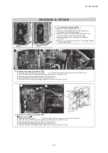
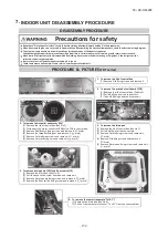
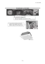
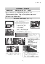
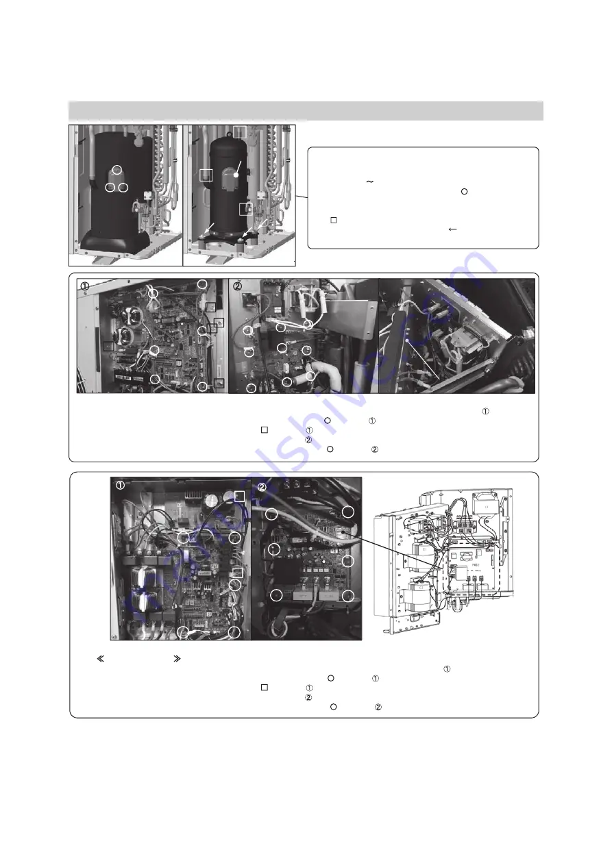
9. To remove the compressor (CM)
(1) Remove the service panel.(See No.1)
(2) Remove the insula
tion
which covers compressors.
(Strings (a) (d) should be loosen.)
(3) Remove 3 terminal cove
r fi
xing bolts( mark) and
remove it and disconnect the power wiring.
(4) Remove welded part of compressor by welding.
( mark)
(5) Remove 3 compressor
fixing
nuts( mark) using spanner
or adjustable wrench.
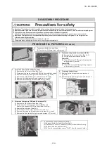
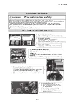
10. To remove the printed circuit board (PCB)
(1) Remove the service panel and top panel.
(2) Pull o
ff
all the inserted connectors of control PCB.(Pic. )
(3) Tak
e off 6
control PCB
fi
xing locking support and remove it.( mark, Pic. )
(4) Remove 5 plate
fixin
g screws and open it.( mark, Pic. )
(5) Pull o
ff
all the inserted connectors of inverter PCB.(Pic. )
(
6
) Tak
e off 9
inverter PCB
fi
xing locking support and remove it.( mark, Pic. )
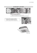
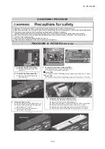
11. To remove the printed circuit board (PCB)
Hinge control type
(1) Remove the service panel.
(2) Pull o
ff
all the inserted connectors of control PCB.(Pic. )
(3) Tak
e off 5
control PCB
fi
xing locking supports and remove it.( mark, Pic. )
(4) Remove 2 plate
fixin
g screws and open it.( mark, Pic. )
(5) Pull o
ff
all the inserted connectors of inverter PCB.(Pic. )
(
6
) Tak
e off 6
inverter PCB
fi
xing locking supports and remove it.( mark, Pic. )
PROCEDURE & PICTURES
(a)
(b)
(c)
(d)
Terminal cover
Control PCB
Inverter PCB
Control PCB
fi
xing plate
Summary of Contents for FDC224KXZME1
Page 169: ... 168 18 KX SM 292 PHA012D402 ...
Page 170: ... 169 18 KX SM 292 Screw ...
Page 171: ... 170 18 KX SM 292 ...
Page 172: ... 171 18 KX SM 292 ...


