–
166
–
'18 • KX-SM-292
Precau
tions for s
a
fety
Read
th
e
se "
Precau
tions for s
a
f
e
ty" c
are
f
ull
y b
e
fo
re
st
ar
tin
g
d
i
s
a
ssemb
l
y wor
k
a
nd do
i
t in th
e
pro
pe
r way
.
W
h
e
n d
i
s
a
ssemb
li
n
g,
b
e
sur
e
to t
u
rn off th
e
p
ow
e
r. Wh
e
n d
i
sass
e
mb
li
n
g
th
e
elec
trica
l
c
om
p
on
e
nts,
c
h
ec
k th
e
elec
trica
l
wirin
g
di
agra
m.
T
h
e
elec
tr
ical
c
om
p
on
e
nts
are
u
n
de
r h
ig
h vo
l
ta
ge
by th
e
o
pera
tion of th
e
boost
e
r
capaci
tor.
Full
y
di
sch
arge
th
e
capaci
tor b
e
for
e
c
omm
e
n
ci
n
g
a r
epai
r wor
k.
Fa
ilure
to obs
e
rv
e
th
i
s w
ar
n
i
n
g
c
o
ul
d r
e
su
l
t
i
n
elec
tri
c
sho
ck.
W
h
e
n parts of r
e
f
rigera
nt
c
y
cle
i
s d
i
s
a
ssemb
led
by w
eldi
n
g,
b
e
sur
e
to wo
rk
aft
e
r co
llec
tin
g
a r
e
f
rigera
nt
,
i
f th
e
r
e
f
rigera
nt
i
sn
'
t
c
o
llec
t
ed,
th
e
u
n
i
t m
ig
ht
expl
o
de.
Be
sur
e
to
c
o
llec
t r
e
f
rigera
nt w
i
thout spr
eadi
n
g
i
t
i
n th
e
a
ir.
T
h
e
se
c
ont
e
nts
are
an
exa
m
ple.
Pl
eas
e
r
e
f
e
r to
a
s
i
m
il
ar
pa
rt of
ac
t
ual
u
n
i
t.
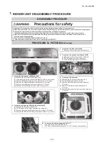
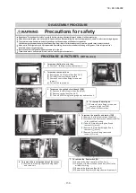
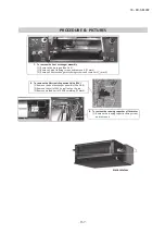
1. T
o remov
e
the
lid
of
c
ontro
l
bo
x
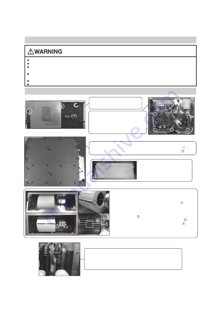
(1) Remove 2 lid
fixing scr
ew
s
a
nd
r
emove it.
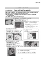
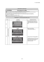
2. T
o remov
e
the p
ri
nt
ed
circ
uit bo
ard
(1) Remove the lid of
con
t
rol
b
ox.
(See No.1)
(2) Pull o
ff
all the i
ns
e
rt
ed
c
o
nn
e
ctors.
(3) Take o
ff 6 con
t
r
ol PCB
fixing
loc
k
ing suppor
t
s
a
nd r
emove it.
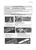
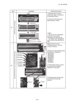
3. T
o remov
e
the bottom
p
an
el(B
)
a
nd bottom
p
an
el(F)
(1) Remove 12 bo
ttom p
a
nel p
a
nel(B)
fix
i
ng scr
ew
s
a
nd
r
emove it.(
mar
k)
(2) Remove 10 bo
ttom p
a
nel p
a
nel(
F)
fixing scr
ew
s
a
nd r
emove it.(
mar
k)
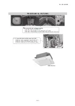
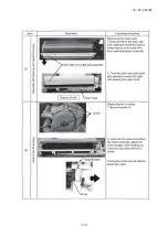
4. T
o remov
e
the d
rai
n
p
an.
(1) Remove the bo
ttom p
a
nel(B)
and
bo
ttom p
a
n
el(F).(See.No.3)
(2) Pull out t
he con
t
orl b
o
x.
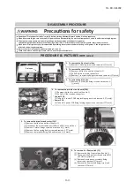
5. T
o remov
e
the
i
m
peller
and motor
(FM)
(1) Remove the lid of
con
t
rol
b
ox.(S
ee No.1)
(2) Remove the bo
ttom p
a
nel(B).
(See No.2)<
Pic.
>
(3) D
isconnec
t the mot
or conn
e
c
t
or(CNFx) in
the
middle of w
iring.
(4) Take
off
the
r
i
g
ht a
nd
le
ft
hook
s
of the fa
n casing
a
n
d
r
emove it.(
mar
k)
(5) Remove t
he impell
e
r fixing b
olt a
nd remov
e it.(
mar
k)
(
6
) Remove
2 motor fixing scr
ew
s
a
nd
r
emove it.(
mar
k)
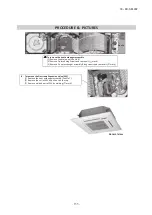
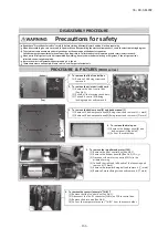
6. T
o remov
e
the sensors
(exa
m
ple
"
T
h
i-R1
"
)
(1) Remove the lid of
con
t
rol
b
ox.(S
ee No.1)
(2) D
isconnec
t t
he Tho-R1 conn
e
c
t
or(CNNx
) o
n
PCB
in
c
o
n
t
rol b
o
x.
(3) Remove the d
rain pan
.(See No.4)
(4) Pull out the
temperature sensor
"Thi-R1" f
rom th
e
s
e
nsor h
olde
r.
DISASSEMBLY
PROCEDURE
PROCEDURE
&
PICTURE
S
(FDUH
s
erie
s)
(T
o
p)
(B
ottom
)
B
ottom
pa
n
el(B)
B
ottom
pa
n
el(F)
C
ont
r
o
l
bo
x
(B
ottom
)
(T
o
p)
Summary of Contents for FDC224KXZME1
Page 169: ... 168 18 KX SM 292 PHA012D402 ...
Page 170: ... 169 18 KX SM 292 Screw ...
Page 171: ... 170 18 KX SM 292 ...
Page 172: ... 171 18 KX SM 292 ...

