–
35
–
'18 • KX-SM-292
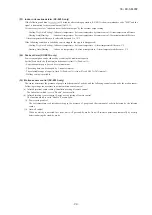
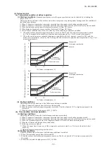
(6) Protective control
(a) Discharge pipe temperature (Td) control
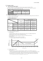
Discharge pipe temperature sensor (Tho-D1) monitors the discharge pipe temperature (Td) to avoid the rise of discharge
pipe temperature.
(i) Compressor capacity control
1) Starting conditions
When all of following conditions are satisfied
➀
When the compressor is ON state.
➁
When it detects the discharge pipe temperature (sensed by Tho-D1) is higher than 120ºC
2) Control contents
Whenever it detects the discharge pipe temperature is higher than 120ºC for 5 seconds, the capacity is decreased.
3) Ending conditions
When any of the following conditions is satisfied
➀
When the discharge pipe temperature (sensed by Tho-D1) drops below 110ºC
➁
When the compressor is OFF state.
➂
During the defrost operation
(ii) Indoor EEV slightly open control at heating stop
Rise of discharge pipe temperature (Td) is restarined by opening the indoor EEV during heating stop.
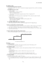
(b) Over-current protection control (Current safe)
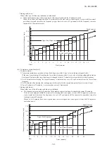
(i) If the input current value at the inverter inlet (converter inlet L3-phase) exceeds the setting value, the compressor
speed is reduced. If the higher value persists even after the speed reduction, the speed is reduced further.
(ii) This control terminates when it is lower than the reset value for 3 minutes continuously or lower than the setting
value for 6 minutes continuously.
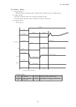
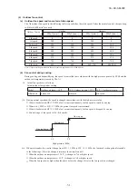
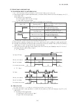
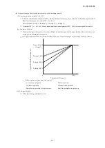
(c) Power transistor temperature (PT) protective control
If the power transistor temperature exceeds 75°C, the compressor speed is controlled.
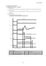
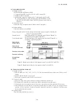
(7) Test run
(a) Starting conditions
(i)
(ii) Pump down switch (SW5-3) must be turned OFF.
(b) Contents of control
operation.
1) Cooling operation
Compressor operation frequency control is conducted by the cooling low pressure control.
2) Heating operation
Compressor operation frequency control is conducted by the heating high pressure control.
(c) Ending conditions
(i) When the test run switch (SW5-1) is turned OFF, it stops.
(ii) When it has stopped anomalously by the error control during test run, the error is displayed in the same way as the
case of normal operation and the state of anomalous stop is kept ON even if the test run switch (SW5-1) is turned
OFF.
Speed is reduced once each minute
Retention
Release
72
75
Power transistor temperature (°C)
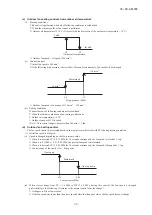
Turn ON the test run switch (SW5-1). The switch is invalid if it is turned ON before the power ON.
(i) Turning ON the dip switch (SW5-2) conducts cooling operation and turning OFF (SW5-2) conducts heating
(ii) Test run start signal under corresponding operation mode is transmitted to all indoor units connected.
(B) Option controls
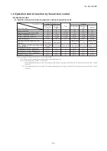
• Functions of outdoor PCB connector CnS1, CnS2, CnG1, CnG2 and CnZ1
①
CnS1 connector :
By changing the allocation of external input functions [P07-
“
X
”
] on the 7-segment, following
functions can be selected.
②
CnZ1 connector : By changing the allocation of external output functions [P06-
“
X
”
] on the 7-segment, following
functions can be selected.
Function No.
“
X
”
CnS1 short circuited
CnS1 open
“0” : External operation input
Operation permission
Operation prohibition
“1” : Demand input
Invalid
Valid
“2” : Forced cooling / heating input
Heating
Cooling
“3” : Silent mode input 1
Valid
Invalid
“4” : Oil return control inpu t
ON
OFF
“5” : Outdoor fan snow guard control input
Valid
Invalid
“6” : Test run external input 1
Test run start
Normal operation
“7” : Test run external input 2
Cooling test run
Heating test run
“8” : Silent mode input 2
Valid
Invalid
“9” : 2-step demand input
Invalid
Valid
* [P07] for CnS1, [P08] for CnS2, [P09] for CnG1 and [P10] for CnG2
“0” : Operation output
“1” : Error output
“2” : Compressor ON cutput
“3” : Fan ON output
“4” : Oil return operation output
“5” : High pressure control output for activating splaying system
“6 – 9” : Spare
*
Summary of Contents for FDC224KXZME1
Page 169: ... 168 18 KX SM 292 PHA012D402 ...
Page 170: ... 169 18 KX SM 292 Screw ...
Page 171: ... 170 18 KX SM 292 ...
Page 172: ... 171 18 KX SM 292 ...


