–
42
–
'18 • KX-SM-292
(8)
Pump down operation control for removal of the unit
When an outdoor unit is discarded or removed, the pump down control is performed at the outdoor unit side in order to
recover the refrigerant quickly to the outdoor unit.
(a) Starting conditions
This is implemented with the liquid service valve closed.
(i) Outdoor unit operation mode – Stop
(ii) Turn ON the test run cooling switch SW5-2 (cooling).
(iii) Turn ON the pump down switch SW5-3 (pump down).
(iv) Turn ON the test run switch SW5-1 when the above (i)-(iii) statuses are satisfied.
Note (1) Input before the power ON is invalid.
(b) Control contents
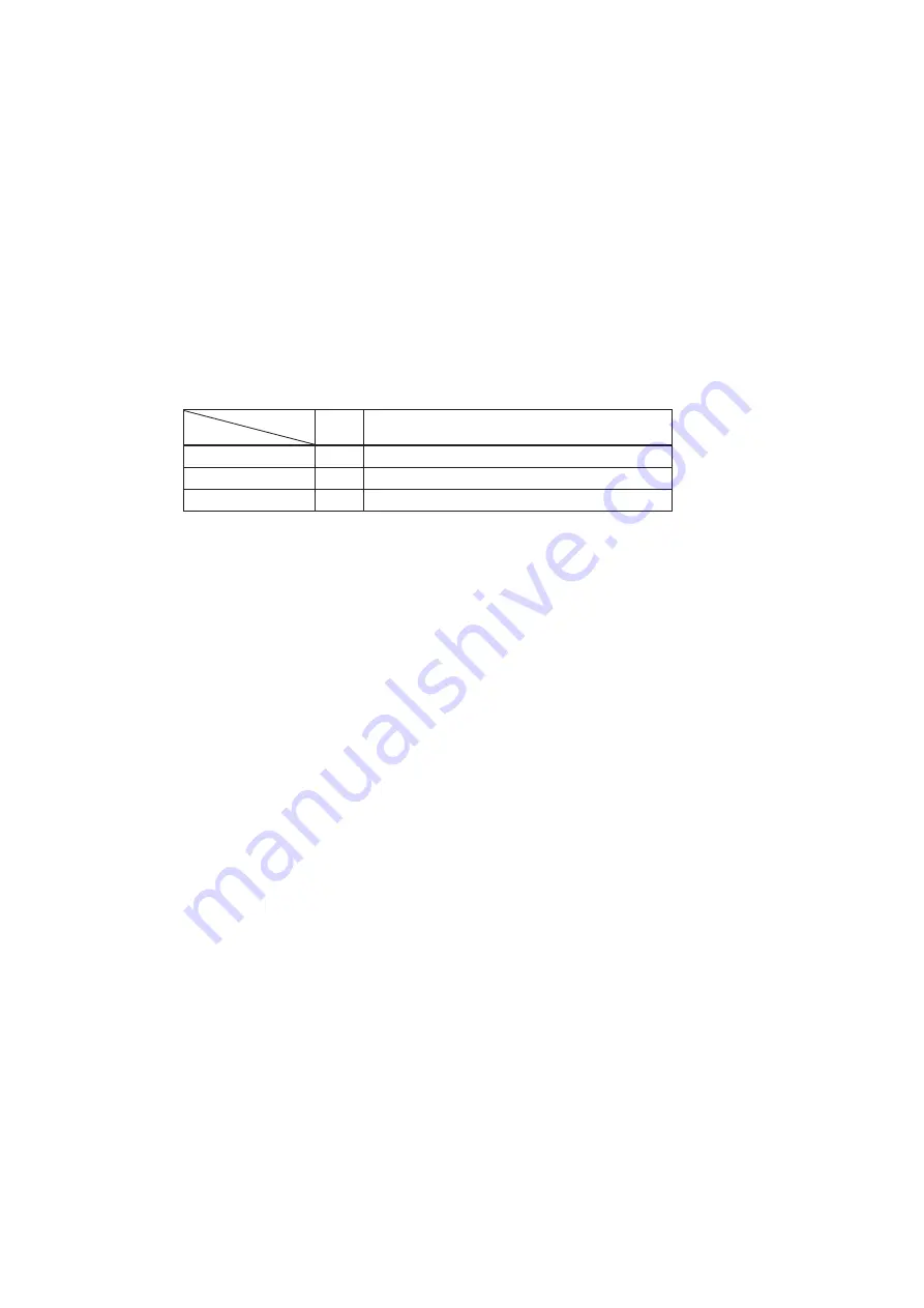
(i) Compressor starts under compressor start protection control and runs at target speed of pump down operation.
However, when the operation starting conditions have been established during the 3-minute delay control of
compressor, the compressor starts after completing the 3-minute delay control.
Item
Model
HP
Target compressor speed at pump down operation
FDC224KXZME1
50rps
FDC280KXZME1
62rps
FDC335KXZME1
52rps
(ii) As the starting conditions are established, both red LED and green LED on the outdoor PCB flash continuously.
7-segment display shows “PdS” (Channel 0) at the code display area.
(iii) During the pump down operation control, the protective controls (excluing low pressure protective control,
anomalous low pressure control and pressure ratio protection control) and the error detection control are effective.
(iv) The sub-cooling coil expansion valve (EEVSC) closes fully during the pump down control.
(c) Ending conditions
If any of the following conditions is satisfied, this control ends
(i) If a low pressure (LP)
≤
0.01MPa is detected for 5 seconds continuously, it ends normally and initiates the
followings.
➀
Red LED: keeps lighting
➁
Green LED: keeps flashin
➂
7-segment display: PdE
➃
Remote control: Stop
(ii)
(iii)
Anomalous all stop by the error detection control
If the cumulative compressor operation time under the pump down control totals 15 minutes (ending by time count
up), it stops and initiates the following.
➀
Red LED: stays OFF
➁
Green LED: keeps flashin
➂
7-segment display: No display
➃
Remote control: Stop
(iv) When any of setting switches (SW5-1, SW5-2 and SW5-3) has been turned OFF during pump down.
Note (1) Even if only the pump down switch SW5-3 is turned OFF, it does not recognized as the cooling test run mode , but stops.
8
10
12
Summary of Contents for FDC224KXZME1
Page 169: ... 168 18 KX SM 292 PHA012D402 ...
Page 170: ... 169 18 KX SM 292 Screw ...
Page 171: ... 170 18 KX SM 292 ...
Page 172: ... 171 18 KX SM 292 ...


