–
58
–
'18 • KX-SM-292
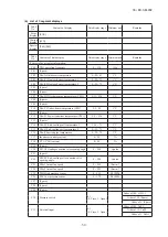
Code
No.
Write contents
Record data
Data write range
Unit of
write
Number of
bytes
Contents
<Error counter information>
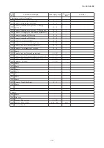
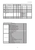
72 Control status HP (63H1) anomaly counter
0 - 5
1
1
73 Control status LP anomaly counter while
running
0 - 5
1
1
74 Control status LP anomaly counter while
stopping
0 - 5
1
1
75 Control status Td1 error counter
0 - 5
1
1
76 Control status DC fan motor 1 error counter
0 - 5
1
1
77 Control status DC fan motor 2 error counter
0 - 5
1
1
78 Control status sensor wire disconnected
counter
0 - 3
1
1
79 Control status INV1 current cut error counter
0 - 4
1
1
80 Control status INV1 starting failure counter
0 - 20
1
1
81 Control status INV1 communication error
counter
0 - 4
1
1
82 Control status INV1 desynchronism error
counter
0 - 4
1
1
83 Control status INV1 communication error
counter cumulative
0 - 255
1
1
84 (Spare) Control status INV1 power transistor
overheat error counter
0 - 4
1
1
85 Control status INV1 rotor lock error counter
0 - 127
1
1
<Setting value display>
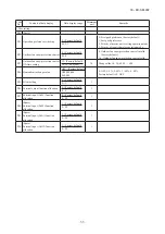
86 Operation priority switching
0 - 3
–
1
0
First push priority
1
Last push priority
2
Director mode
3 Operation mode
capacity priority
87 Outdoor fan snow protection control
0,1
1
0
Valid
1
Invalid
88 Outdoor fan snow protection control ON
time setting
30: (Factory default)
10, 30 – 600 [sec]
10 sec
1
89
Demand ratio change value
OFF, 000, 040, 060,
080
Factory default 0: OFF
–
1
90 Silent mode setting
0 - 9
–
1
91 CnS1 function allocation value
0 - 20
–
1
92 CnS2 function allocation value
0 - 20
–
1
93 CnG1 function allocation value
0 - 20
–
1
94 CnG2 function allocation value
0 - 20
–
1
95 External output function allocation
0 - 9
–
1
96 Target cooling low pressure compensation
-0.20 - +0.20
0.01MPa
1
97 Target cooling high pressure compensation
0.00 - 0.40
0.01MPa
1
98 Heating setting 1 (Target outlet temperature)
40 - 50
1 [°C]
1
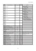
Code
No.
Write contents
Record data
Data write range
Unit of
write
Number of
bytes
Contents
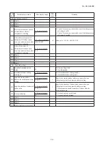
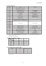
52 DIP switch [SW6]
–
–
1
Bit0
SW6-1
0 : OFF, 1 : ON
Bit1
SW6-2
0 : OFF, 1 : ON
Bit2
SW6-3
0 : OFF, 1 : ON
Bit3
SW6-4
0 : OFF, 1 : ON
Bit4
SW6-5
0 : OFF, 1 : ON
Bit5
SW6-6
0 : OFF, 1 : ON
Bit6
SW6-7
0 : OFF, 1 : ON
Bit7
SW6-8
0 : OFF, 1 : ON
53 Jumper wire
–
–
1
Bit0
J11
0: Open, 1: Short-circuit
Bit1
J12
0: Open, 1: Short-circuit
Bit2
J13
0: Open, 1: Short-circuit
Bit3
J14
0: Open, 1: Short-circuit
Bit4
J15
0: Open, 1: Short-circuit
Bit5
J16
0: Open, 1: Short-circuit
Bit6
(Spare)
Bit7
(Spare)
<PCB hardware output>
54 Relay output
–
–
1
Bit0
52X1, 52X2
0 : OFF, 1 : ON
Bit1
20S
0 : OFF, 1 : ON
Bit2
CH1
0 : OFF, 1 : ON
Bit3
SV1
0 : OFF, 1 : ON
Bit4
SV6
0 : OFF, 1 : ON
Bit5
SV11
0 : OFF, 1 : ON
Bit6
(Spare)
0 : OFF, 1 : ON
Bit7
(Spare) FMC1,2
0 : OFF, 1 : ON
55 Relay output
–
–
1
Bit0
Operation output
(CnH)
0 : OFF, 1 : ON
Bit1
Error output (CnY) 0 : OFF, 1 : ON
Bit2
External output
(CnZ)
0 : OFF, 1 : ON
Bit3
(Spare)
0 : OFF, 1 : ON
Bit4
(Spare)
0 : OFF, 1 : ON
Bit5
(Spare)
0 : OFF, 1 : ON
Bit6
(Spare)
0 : OFF, 1 : ON
Bit7
(Spare)
0 : OFF, 1 : ON
<Related to compressor>
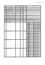
56 CM1 Cumulative operation
hours (Approx.)
0 - 65535
1h
2
57 CM1 Starting times
0 - 65535
× 20
times
2
58 CM1 3-minute delay timer
0 - 180
1 sec
1
59 Energizing time count down
0 - 255
1 min
1
60 Control status CH
Compressor protection timer
0 - 360
3 min
1
61 Control status CH
Compressor protection start
0 - 15
–
1
15
Protection start
complete
0 - 14 Protection start ON
Summary of Contents for FDC224KXZME1
Page 169: ... 168 18 KX SM 292 PHA012D402 ...
Page 170: ... 169 18 KX SM 292 Screw ...
Page 171: ... 170 18 KX SM 292 ...
Page 172: ... 171 18 KX SM 292 ...


