–
65
–
'18 • KX-SM-292
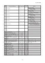
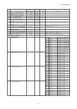
2.3 Contents of troubleshooting
(a) List of inspection displays
1) Indoor and outdoor units
Remote
control
error code
7-segment
display
Name of inspection
Classification
Page
E1
–
Remote control communication error
Communication error
81
E2
–
Duplicated indoor unit address
Address setting error
82
E3
–
Outdoor unit signal line error
Address pairing setting error
83
E5
–
Communication error during operation
Communication error
84
E6
–
Indoor unit heat exchanger temperature sensor anomaly (Thi-R) Sensor wire breakage
85
E7
–
Indoor return air temperature sensor anomaly (Thi-A)
Sensor wire breakage
86
E9
–
Drain trouble
System error
87
E10
–
Excessive number of indoor units (more than 17 units) by
controlling one remote control
Communication error
88
E12
–
Address setting error by mixed setting method
Address setting error
89
E16
–
Indoor fan motor anomaly (FDT series)
DC fan motor error
90
–
Indoor fan motor anomaly (FDK series)
DC fan motor error
91
E19
–
Indoor unit operation check drain pump motor check mode anomaly Setting error
92
E28
–
Remote control temperature sensor anomaly (Thc)
Sensor wire breakage
93
E30
E30
Unmatch connection of indoor and outdoor unit
System error
94
E31
E31
Duplicated outdoor unit address No.
Address setting error
95
E32
E32
Open L3 Phase on power source at primary side
Site setting error
96
E36
E36-1
Discharge pipe temperature error (Tho-D1)
System error
97
E36-3
Liquid flooding anomaly
System error
98
E37
E37-1, 2
E37-5, 6
Outdoor unit heat exchanger temperature sensor (Tho-R)
and subcooling coil temperature sensor (Tho-SC, -H)
anomaly
Sensor wire breakage
99
E38
E38
Outdoor air temperature sensor anomaly (Tho-A)
Sensor wire breakage
100
E39
E39-1
Discharge pipe temperature sensor anomaly (Tho-D1)
Sensor wire breakage
101
E40
E40
High pressure anomaly (63H1-1 activated)
System error
102
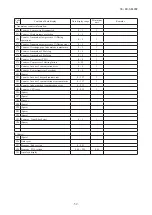
E41 (E51) E41 (E51)-1 Power transister overheat
System error
103
E42
E42-1
Current cut (CM1)
System error
104
E43
E43-1
E43-2
Excessive number of indoor units connected, excessive total
capacity of connection
Site setting erro
E45
E45-1
Communication error between inverter PCB and outdoor unit
control (PCB)
Communication error
E46
E46
Mixed address setting methods coexistent in same network
Address setting error
E48
E48-1
E48-2
Outdoor unit DC fan motor anomaly
DC fan motor error
E49
E49
Low pressure anomaly
System error
109
E53/E55
E53/E55-1 Suction pipe temperature sensor anomaly (Tho-S),
Under-dome temperature sensor anomaly (Tho-C1)
Sensor wire
breakage
110
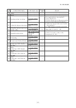
E54
E54-1
E54-2
High pressure sensor anomaly (PSH)/Low pressure sensor
anomaly (PSL)
Sensor wire
breakage
111
E56
E56-1
Power transitor temperature sensor anomaly (Tho-P1)
Sensor wire breakage
112
E58
E58-1
Anomalous compressor by loss of synchronism
System error
113
E59
E59-1
Compressor startup failure (CM1)
System error
114
E60
E60-1
Rotor position detection failure (CM1)
System error
115
E63
E63
Emergency stop
Site setting error
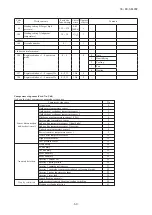
2)
Option control in-use
SL1N-E
SL2NA-E
SL4-AE/BE
Indoor unit
control PCB
Outdoor unit
control PCB
Location of
trouble
Description of trouble
Repair
method
Error
code
Red
LED
Red
LED
Green
LED
Red
LED
Green
LED
E75
Keeps
flashing
Stays
OFF
Keeps
flashing
Stays
OFF
Keep
flashing
・
Communication enor (Deflective comm-
unication circuit on the main unit of
SL1N-E, SL2NA-E or SL4-AE/BE)
Replacement
SL1N-E
SL2NA-E
SL4-AE/BE
106
107
105
108
116
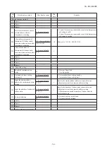
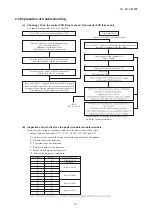
(b)
Troubleshooting
Error code
Remote control:
7-segment display:
LED
Green
Red
Indoor
Outdoor
Content
None
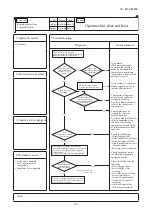
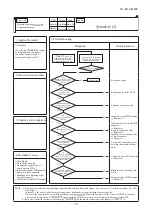
Operates but does not cool
Keeps flashing Stays Off
Keeps flashing Stays Off
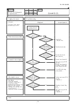
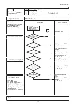
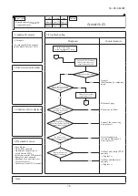
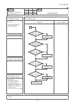
1. Applicable model
5. Troubleshooting
All models
Diagnosis
Countermeasure
NO
YES
YES
NO
YES
YES
YES
NO
NO
NO
YES
NO
Check the indoor fan operation
Check the temperature difference between
return and suction air of indoor unit
Mistake in model selection.
Calculate heat load once more.
Check following operation control function.
. Control for determing compressor rotation speed
. Protective control by controlling compressor
rotation speed
Which control is appropriate to this phenomenon
The unit is operating normally, but is operating
under the protective control of compressor or
other respective components
Is the
temperature differnce
between return and
suction air 10-20ºC at
cooling?
Does the
heat load increase after
installtion?
Is the compressor
operating?
Is the
compressor rotation
speed low?
Is the
operating conditions of
indoor/outdoor unit
under rated condition?
" WAIT "
message is displayed [for
3 seconds] when performing
cooling, defumidifying or heating
operation from remote
control?
Note (1) Outdoor: 35ºC
Indoor : 27ºCDB/19ºCWB
It is normal.
(This unit is designed to
start in the soft start mode
by detecting the compressor
under-dome temperature
when it restart after power
reset.)
It is necessary to replace to
higher capacity unit or to
install additional unit.
Compressor refrigerant oil
protective control at starting
is activated.
For the contents of control, refer
to the compressor start control.
Compressor may be stopped
by the error detection control.
For the contents of control,
refer to anomalous stop
control by controlling
compressor rotation speed
of microcomputer control
function.
Check the followings
• Minor clogging of filter
• Minor fouling of heat exchanger
• Minor short-circuit of air
flow
• Slightly insufficient or excessive
refrigerant amount
• Poor compression of compressor
Check suspicious points
considering appropriate
operation control.
Check the followings for
reference
• Severe clogging of filter
• Severe clogging of heat
exchanger
• Severe short-circuit of
air flow
• Severely insufficient or
excessive refrigerant
amount
• Under protective control of
compressor
• Indoor unit fan tap setting
• Valid setting of silent mode
2. Error detection method
3. Condition of error displayed
4. Presumable cause
• Poor compression of
compressor
• Expansion valve anomaly
Note:
Summary of Contents for FDC224KXZME1
Page 169: ... 168 18 KX SM 292 PHA012D402 ...
Page 170: ... 169 18 KX SM 292 Screw ...
Page 171: ... 170 18 KX SM 292 ...
Page 172: ... 171 18 KX SM 292 ...

