–
118
–
'14 • KX-SM-221
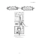
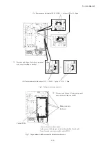
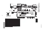
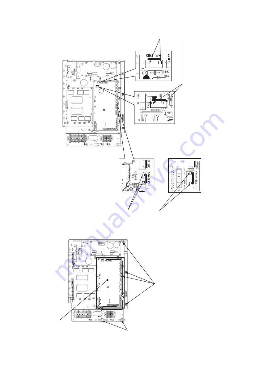
Fig.2 Voltage measurement points
(A) Power source for control PCB : CNA1, 1 3pin or CNA2, 1 -
-
4pin
(
+
)
(
−
)
(B) Power source for fan motor (DC) : CNA2, 1 - 3pin or CNA1, 1 - 4pin
(
+
)
(
−
)
(
+
)
(
−
)
(
+
)
(
−
)
※
:
Presence and shape of electric component
may vary according to a model.
or
or
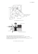
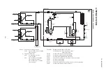
Fig. 3 Target places which are removed harnesses and screws
Remove screws.
(4 places)
Remove harnesses from bands.
And, remove the harnesses which are bundled by these bands
from clips and connectors on the control PCB.
※:
Presence and shape of electric component
may vary according to a model.
Control PCB

