–
143
–
'14 • KX-SM-221
5.2 Method for connecting the accessory pipe
●
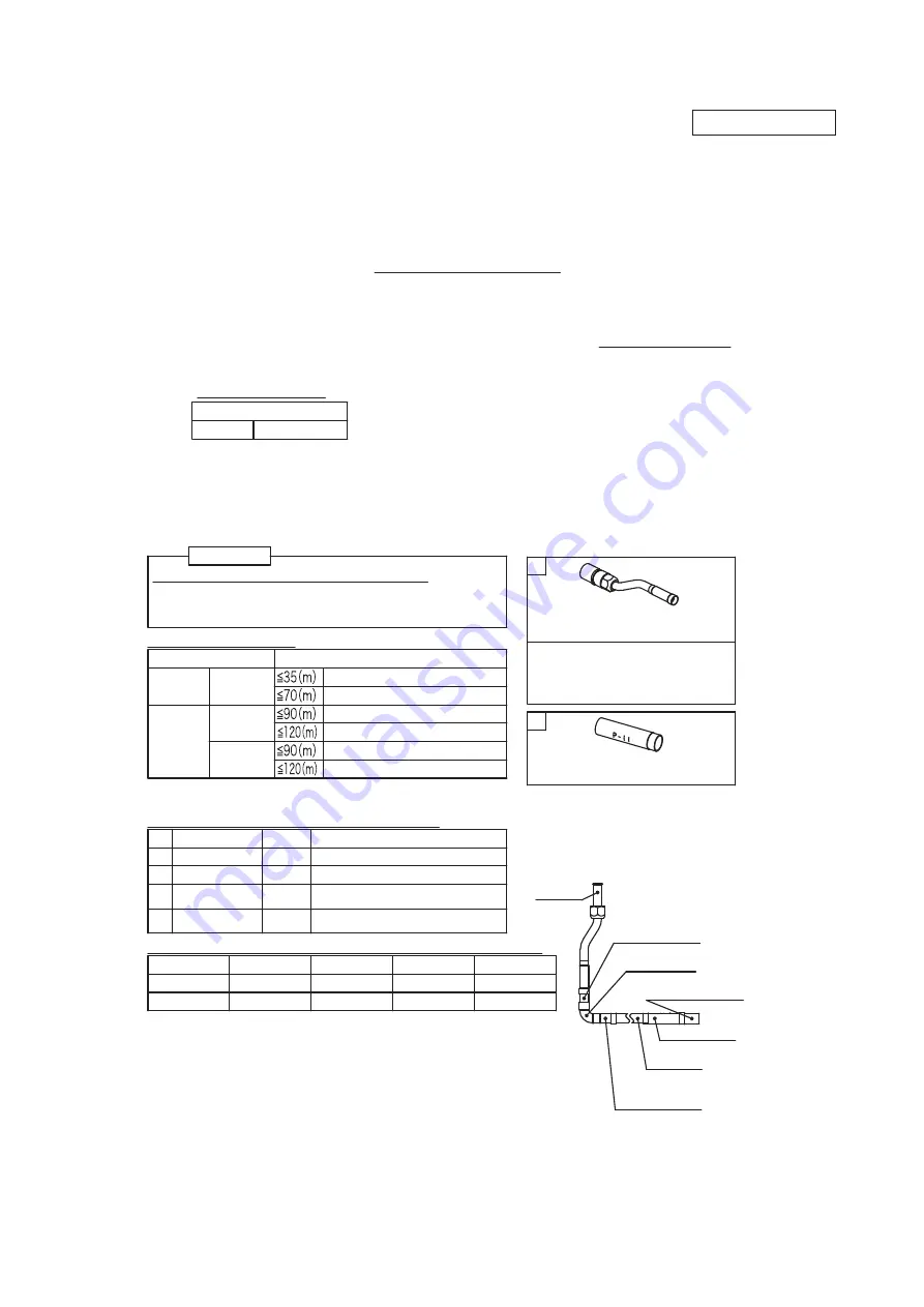
Be sure to use the accessory pipe to connect the operation valve on the gas side with the field pipe.
Be sure to ues the straight pipe (Procured at the field) shown in the table 1 applicable to the model
●
of outdoor unit.
●
When tightening the flare, connect the pipe securely by pressing the flared face of pipe against
the operation valve.
●
When brazing between the pipe in place and the attached pipe, confirm that no excessive force is
applied to the flare joint. Otherwise gas could leak from the flare joint.
●
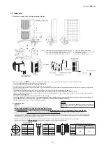
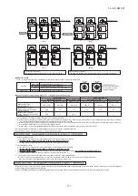
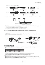
Connect the attached pipe according to the following steps
①〜⑤
.
Referring to Table 2 and Table 3, prepare the straight pipe and the elbow in the field, which are
used in the construction examples
Ⓐ〜Ⓓ
applicable to the connecting direction.
Firstly, use the accessory pipe to assemble the connecting pipe assembly outside the outdoor unit.
(
As showm in the figure of connecting examples
Ⓐ〜Ⓓ.)
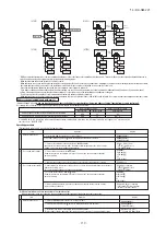
After assembling the connecting pipe, connect it to the operation valve on the gas side
inside the outdoor unit. Tighten the flare nut with appropriate torque.
After connection of the connecting pipe assembly to the operation valve on the gas side,
braze the connecting pipe assembly and the field pipe.
When connecting pipe contacts wiring, attach heat insulating material to the pipe in order to prevent
from contacting of the pipe and wiring. (If the wiring is rubber with the pipe and the cover of wiring
is teared, there is a risk of a short circuit or an electtric shock.
)
①
②
③
④
⑤
Proper torque
φ
19.05 100
〜
120N
・
m
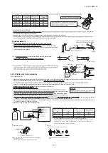
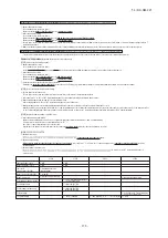
About brazing
●
Be sure to braze while supplying nitrogen gas.
If no nitrogen gas is supplied, a large amount of impurity
(
oxidized film) will be generated, which may clog the capillary
tube and the expansion valve, resulting in fatal malfunction.
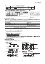
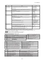
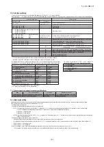
Table 2 Parts used for the connecting pipe assembly
Table 1 Pipe specification
(
m
)
h
t
g
n
e
l
)
y
a
w
e
n
o
(
e
n
il
t
n
a
r
e
g
ir
f
e
R
φ
22.22 x T1.0
φ
25.4 x T1.0 or
φ
28.58 x T1.0
●
Be sure to use pipes of 1
/
2H material, and wall thickness
above 1mm. (Pressure resistance of O-type pipe is not enough)
No.
Name
Quantity
Remark
Accessory pipe A
Straight pipe
①
Straight pipe
②
Elbow
1
2
3
4
1
1
1 or 0
1 or 0
Accessory
Procured at the field
Procured at the field
(
Not required for downward direction
)
Procured at the field
(
Not required for downward direction
)
Table 3 Length and specification of straight pipe
(
Procured in the field
)
Straight pipe
①
Straight pipe
②
400mm or more 192.5
〜
202.5mm 192.5
〜
202.5mm
-
105mm or more 155mm or more
210mm
370mm or more
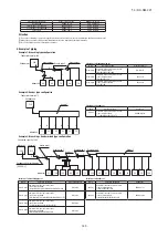
Ⓐ
Downward
Ⓑ
Forward
Ⓒ
Rightward
Ⓓ
Backward
Heat insulating material is attached
to the accessory pipe with band.
When installing the heat insulating
material, cut the band and retrieve it.
●
Branching pipe set can be used by
using the accessory pipe B.
When
φ
22.22
(
OD
)
size of the
indoor unit gas pipe is used, the
accessory pipe B is unnecessary.
A
B
Straight pipe
①
φ
22.22
(
OD
)
to be
procured locally
Straight pipe
②
φ
22.22
(
OD
)
to be
procured locally
Field piping
φ
22.22
(
OD
)
Branching pipe set
(
DIS-WB1G,DIS-TB1G
)
Elbow to be
procured locally
Accessory pipe B
250V
224KXZPE1
280KXZPE1
Single type
Multi type
φ
19.05 x T1.0
φ
22.22 x T1.0
φ
22.22 x T1.0
φ
25.4 x T1.0 or
φ
28.58 x T1.0
Accessory pipe A x 1 pc
(
Except 224KXZPE1
)
Accessory pipe B x 1 pc
(
Only use for 250V
)
※
In case of V-multi
(
In case of 250V
)
Accessory
pipe A
PSC012D028C

