background image

– 

86

 –

 '14 • KX-SM-221

-

71-1

-

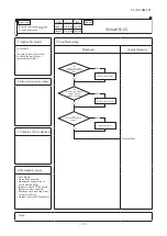
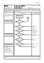
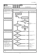
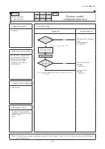
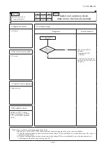
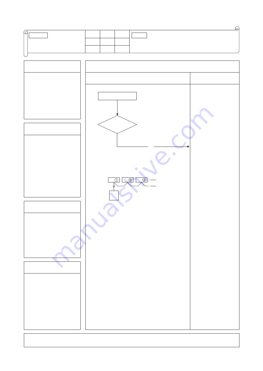
E11

Address setting error between

master and slave indoor units

Keeps flashing Keeps flashing

1.Applicable model

5. Troubleshooting

All models

Diagnosis

Countermeasure

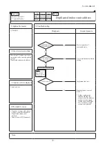
• In cases of RC-E5

Return address No. to 
“IU …” using [▲ ] or 
[ ▲ ] button.

• In cases of RC-EX1A 

Menu ➞

 Next

➞ IU settings ➞ Select IU

2. Error detection method

IU address has been set using 
the “Master IU address set” 
function of remote control.

3.Condition of Error displayed

Same as above

4. Presumable cause

Same as above

Note:

Is “Master IU 

address set” function of remote

 control used?

E11 occurs 

YES

Error code 

Remote control:

LED

Green

Red 

Indoor

Content

IU

IU

IU

R/C

In case the wiring is below and “Master IU address 
set” is used, E11 is appeared.

#

Error code 

Remote control:
7-segment display:

LED 

Green 

Red 

Indoor 

Outdoor 

Content 

E11

Address setting error between

master and slave indoor units

Keeps flashing

Stays OFF

Keeps flashing

Stays OFF

Summary of Contents for FDC224KXZPE1

Page 1: ...VERTER MULTI SYSTEM AIR CONDITIONERS KXZ Outdoor units Manual No 14 KX SM 221 Single use FDC224KXZPE1 280KXZPE1 KXZP series 1 Regarding the indoor unit series refer to the No 14 KX DB 206 Note SERVICE MANUAL ...

Page 2: ...lanation of troubleshooting 58 2 3 Contents of troubleshooting 61 2 4 Outdoor unit control PCB replacement procedure 115 2 5 Outdoor unit inverter PCB replacement procedure 117 2 6 Outdoor unit converter PCB replacement procedure 120 2 7 Outdoor unit transistor module replacement procedure 122 2 8 Outdoor unit diode module replacement procedure 123 3 ELECTRICAL WIRING 125 4 PIPING SYSTEM 126 5 APP...

Page 3: ... set temp button Displays the temperature which is set currently Tap this button to change the set temperature Change operation mode button Displays the operation mode which is selected currently Tap this button to change the operation mode Timer button Displays simplified contents of the timer which is set currently When two or more timers are set contents of the timer which will be operated imme...

Page 4: ...nt mode Cover AIR CON No button Display the indoor unit number connected to this remote control CHECK button This button is used at servicing TEST button This button is used during test operation Weekly timer display Displays the settings of the weekly timer Operation setting display area Displays setting temperature airflow volume operation mode and oparation message Operation check indicator lig...

Page 5: ...n this is pressed once again it stops operating Used to swing the louver Every time this button is pressed displays switch as below Sets room temperature by pressing or button Sets time when setting the time Used to cancel the TIMER SETTINGS Used to reset the microcomputer Indicates the selected airflow volume Indicates when ON TIMER is set Indicates the ON TIMER setting time Nothing displayed whe...

Page 6: ...rd 4 digit number TOP screen Menu screen 1 Menu screen 3 Service password input Tap the Menu button on the TOP screen Main menu screen is displayed Tap the Service Maintenance on the menu screen Display the service password input screen Enter the service password 4 digit number TOP screen Menu screen 1 Menu screen 3 Service password input Service maintenance menu 1 Service maintenance menu 2 Servi...

Page 7: ...etting of silent mode is cancelled regardless whether the power failure compensation is effective or not a At power failure Operating stopped If it had been operating under the off timer mode sleep timer mode the state of stop is memorized Although the timer mode is cancelled at the recovery from power failure the setting of weekly timer is changed to the holiday setting for all weekdays b Operati...

Page 8: ...ter the elapse of the set time period the current set temp will be set back to the Set back temp The setting can be done in cooling and heating mode respectively The selectable range of the set time is from 20 min to 120 min 10 min interval Set the Set back temp by 1 interval 6 Filter sign reset メ ニュー 7番目 A 1 Filter sign reset B 2 Setting next cleaning date A 7 Initial settings メ ニュー 8番目 1 Clock s...

Page 9: ...n speed setting Valid or Invalid of Auto fan speed setting can be selected B B B B B A A A A Main indoor unit address can be set Only the Main indoor unit can change operation mode and the Sub indoor units dominated by the Main indoor unit shall follow The Main indoor unit can domain 10 indoor units at a maximum 12 Installer settings 13 RC function settings Setting display item 11 Administrator se...

Page 10: ...e of stop is memorized Although the timer mode is cancelled at the recovery from power failure the setting of weekly timer is changed to the holiday setting for all weekdays b Operation mode c Airflow volume mode d Room temperature setting e Louver auto swing stop However the stop position 4 position is cancelled so that it returns to Position 1 f Remote control function items which have been set ...

Page 11: ...indoor unit fan tap at the thermostat ON is retained so far as the thermostat is turned OFF 3 Timer operation a RC EX1A i Sleep timer Set the time from the start to stop of operation The time can be selected in the range from 30 to 240 minutes in the unit of 10 minute Note 1 Enable the Sleep timer setting from the remote control If the setting is enabled the timer operates at every time ii Set OFF...

Page 12: ...n parallel when the times to turn ON and OFF the air conditioner are duplicated the set ting of the OFF timer has priority 4 Remote control display during the operation stop When the operation is stopped the power source is turned ON it displays preferentially the Room temperature Center Remote Filter sign Inspection and Timer operation 5 Hot start Cold draft prevention at heating a Operating cond...

Page 13: ... the indoor heat exchanger temperature detected with ThI R1 or R2 drops to 35 C or lower the speed of indoor fan is changed to the lower tap at each setting ii During the hot keep the louver is kept at the horizontal position b Ending condition When the indoor fan is at the lower tap at each setting it returns to the set airflow volume as the indoor heat exchanger temperature rises to 45 C or high...

Page 14: ...vent the cold start The louver position display LCD continues to show the display which has been shown before entering this control iii Louver free stop control When the louver free stop has been selected with the indoor function of wired remote control POSITION the louver motor stops when it receives the stop signal from the remote control If the auto swing signal is received from the remote cont...

Page 15: ... including stop this control is stopped immediately and the operating condition is restored v When the Fan OFF is selected the fan on the indoor unit of which the thermostat has been turned OFF is turned OFF The same occurs also when the remote control sensor is effective d Fan control during cooling thermostat OFF i Following fan controls during the cooling thermostat OFF can be selected with the...

Page 16: ...s after the compressor ON 1 OFF OFF 3 minutes delay Thermostat OFF in the condition of 9 Compressor Indoor unit A Thermostat Indoor unit B Thermostat 11 Drain pump control a This control is operated when the inverter frequency is other than 0 rps during the cooling operation and automatic cooling and dehumidifying operations b Drain pump ON condition continues for 5 minutes even when it enters the...

Page 17: ...ending on each operating condition 13 Operation check drain pump test run operation mode a If the power is turned on by the dip switch SW7 1 on the indoor PCB when electric power source is supplied it enters the mode of operation check drain pump test run It is ineffective prohibited to change the switch after turning power on b When the communication with the remote control has been established w...

Page 18: ...ops E6 18 External input output control CnT or CnTA Be sure to connect the wired remote control to the indoor unit Without wired remote control remote operation by CnT is not possible to perform CnT CnTA Operation output CnT 2 XR1 Heating output CnT 3 XR2 Thermostat ON output CnT 4 XR3 Error output CnT 5 XR4 Remote operation input CnT 6 Volt free contact XR1 1 2 3 4 5 6 XR3 XR4 CnT Blue 12V XR2 Op...

Page 19: ...e indoor function setting of Level input Factory default or Pulse input is selected by the function for External input of the wired remote control operation status will be changed as follows i In case of Level input setting Factory default Input signal to CnT 6 or CnTA is OFF ON unit ON Input signal to CnT 6 or CnTA is ON OFF unit OFF Operation is not inverted ON ON OFF OFF OFF ON ON ON ON Remote ...

Page 20: ...key switch is ON CnT 6 or CnTA ON Operation permission start stop operation of the unit from the wired remote control becomes available When card key switch is OFF CnT 6 or CnTA OFF Operation prohibition the unit stops operation in conjunction with OFF signal and start stop operation of the unit from the wired remote control becomes not available 2 In case that Operation permission prohibition mod...

Page 21: ...e input is set for the indoor unit function If the external input is changed OPEN CLOSE operation modes are inverted Cooling Heating or Heating Cooling Operation Operation Operation Stop Stop Stop Stop Operation prohibition Operation prohibition Operation prohibition Operation prohibition Operation prohibition Operation prohibition Operation permission Operation permission Operation permission Ope...

Page 22: ...is installed at the ceiling where warm air tends to accumulate the setting can be changed with the wired remote control indoor unit function The compressor and the heater are turned ON OFF at one of the setting temperature 3 2 or 1 C in order to improve the feeling of heating The setting temperature however has the upper limit of 30 C Compressor Compressor Standard Operation Stop Setting temperatu...

Page 23: ...wer than 25 C unit goes thermo OFF 30 Auto fan speed control RC EX1A only In order to reach the room temperature to the set temperature as quickly as possible the airflow rate is increased when the set temperature of thermostat differs largely from the return air temperature According to temperature difference be tureen set temperature and return air temperature indoor fan tap are controlled autom...

Page 24: ...losed Fully closed 2 Fully closed Fully closed Solenoid valve SV1 liquid injection 〇 〇 〇 Solenoid valve SV6 oil return return 〇 〇 〇 〇 〇 Crankcase heater CH 〇 〇 〇 〇 〇 〇 Note 1 It means 〇 ON OFF 〇 ON or OFF 〇 ON OFF 2 This shows the state of output when all indoor units are under the same mode 3 1 When stopped from cooling it is fully open When stopped from heating it is fully closed unless another ...

Page 25: ...or frequency b Minimum compressor frequency Model Cooling Heating A range B range B range A range 5 10 Outdoor air temperature 224 92 96 116 280 120 120 124 Unit rps Model Cooling Heating A range B range B range A range 0 5 Outdoor air temperature 224 20 20 40 280 20 20 40 Unit rps ...

Page 26: ...re value iii Under low outdoor air temperature condition the stepless fan control between 130 300min 1 is performed Outdoor fan tap Cooling Heating FMo1 min 1 FMo2 min 1 FMo1 min 1 FMo2 min 1 0th speed 0 0 0 0 1th speed 200 0 200 0 2th speed 200 200 200 200 3th speed 300 300 300 300 4th speed 390 390 390 390 5th speed 530 530 530 530 6th speed 600 600 600 600 7th speed 730 730 730 730 8th speed 82...

Page 27: ...r temperature C TA Outdoor air temperature C Fig 1 Cold region Standard Factory setting Defrost start zone 2 6 15 19 21 25 20 15 6 Without J15 Cold region specification With J15 SST Suction pressure saturated temperature C Fig 2 Cold region Standard Factory setting Defrost start zone 6 10 19 23 25 29 20 15 6 Without J15 Cold region specification With J15 ii End conditions Standard J14 is shorted 1...

Page 28: ... control i Current sensor built in the power transistor monitors current values output from the inverter If the value exceeds the setting value the current cut control stops the compressor The compressor starts automatically 3 minutes after the stop ii If the above control activates 4 times within 15 minutes and the operation is stopped with the error stop State of the error continues for 3 minute...

Page 29: ...ulse input Switching of operation permission operation prohibition modes Reversal Open Short circuit Short circuit Level input Operation permission mode Operation prohibition mode Open Pulse input NOP Note 1 Factory setting J13 Short circuit CnS1 Short circuit Short circuit pin connected iii The operation condition is desplayed on the LCD of remote control and is transfered to optional centralised...

Page 30: ...on mode to permission mode the indoor units operation status can be select by 7 segment P17 setting 7 segment P17 0 Keeping STOP 7 segment P17 1 Automatically RUN b Demand control Note With 7 segment P07 1 i Demand control and normal operation are switched with the connector CnS1 and the jumper wire J13 on the outdoor PCB J13 Switching of CnS1 input method J13 short circuit CnS1 is for the level i...

Page 31: ... PUSH PUSH PUSH PUSH J13 Open OFF OFF ON ON Demand control Demand control CnS1 input Remote control operation Remote control display Air conditioner operation stop Remote Compressor Demand CompressorDemand PUSH PUSH PUSH PUSH c Demand control from indoor unit i Starting condition When a demand ratio 80 60 40 or 0 has been transmitted from an indoor unit of Peak cut timer function Normal demand of ...

Page 32: ...l contents Upper limit of compressor speed and upper limit of outdoor fan speed are restricted according to the established start i External input setting Capacity priority ii External input setting Sound level priority c End condition When the starting conditions are not established Item Setting Upper limit of compressor speed Upper limit of outdoor fan speed rps min 1 224 280 224 280 Silent sett...

Page 33: ... Snow protection control setting is invalid P02 0 or outdoor air temperature 5 C and external input of outdoor fan snow protection control OFF P07 5 and CnSl is opend ii Compressor ON iii During all stop by anomaly Valid Invalid Outdoor air temperature C 3 5 Outdoor air temperature condition at snow protection control 4 External output This function is used in order to operate the external option ...

Page 34: ... est Master indoor unit When the master indoor unit is turned off it become valid the first push priority on other indoor units remote controls Priority of required major operation mode Operation mode of which the total capacity of operating indoor units is larger There is no renewed judgment for 10 minutes after a change on the operation mode The judgment however is renewed in following cases At ...

Page 35: ... Cooling heating unmatched When unmatch occurs among indoor units it can be reset by either one of followings If the operation mode of outdoor unit is matched with that of indoor unit If the operation mode is changed to Fan or Stop on the indoor units on which Cooling heating is unmatched Indoor unit 0 Stop Fan Fan ON Indoor unit 1 Stop Heating Heating ON Indoor unit 0 Stop Cooling Invalid operati...

Page 36: ...d it is changed to the fan operation P18 1 It is operated with the forced cooling heating operation mode Setting temperature for cooling 28 Setting temperature for heating 20 7 Emergency stop control When one of indoor units receives the emergency stop signal through CnT terminal on the indoor control PCB from the device like as refrigerant leakage detector and that information is transmitted to t...

Page 37: ...ed LED and green LED on the outdoor PCB flash continuously 7 segment display shows PdS Channel 0 at the code display area iii During the pump down operation control the protective controls excluing low pressure protective control anomalous low pressure control and pressure ratio protection control and the error detection control are effective iv The sub cooling coil expansion valve EEVSC closes fu...

Page 38: ... indoor units which are operating with the thermostat ON a Correction of target high low pressure i Starting condition either of or When the external input function assignment P07 Multi system energy save control Valid When 7 segment P69 Multi system energy save control I ON if the external input function assignment P07 is not assigned this control ii Contents of control During the outdoor unit op...

Page 39: ...his control ii Contents of control Compressor upper limit speed is the value obtained by multiplying with the upper limit speed restriction rate ac cording to the thermostat ON capacity The upper limit restriction rate is divided to the following 3 steps according to each setting of P16 as follows Following controls supersede this control 4 way valve safeguard Defrost operation Oil return operatio...

Page 40: ... Example If SW9 is pressed at the code No C07 displayed it jumps to the code No C10 If SW9 is pressed 7 The data of code No C44 can be erased independently The compressor cumulative operation time corresponding to the code No selected can be erased reset For resetting of the compressor cumulative operation time after replacement of compressor The resetting method is to select the code C44 first The...

Page 41: ...his data might be unreliable as sub cooling degree but the result is displayed as it is C50 Suction superheat degree Suction pipe temperature C detected with suction pipe temperature thermistor Tho S Low pressure saturated temperature C detected with low pressure sensor PLS C51 Superheat degree of sub cooling coil Sub cooling coil temperature C detected with sub cooling coil temperature thermistor...

Page 42: ...SH High pressure sensor C30 0 1 63H1 í Order of 100 63H1 Order of 10 Spare 0 Close 1 Open 60 Opening angle of EEVH1 expansion valve for heating FM01 Number of rotations 10min 1 C27 0 50 1A Inverter secondary current 1 Order of 1 Spare C31 0 1 CNS1 í Order of 100 CNS1 Order of 10 Spare 0 Close 1 Open Order of 1 Spare C33 0 1 52X2 í Order of 100 52X2 Order of 10 Spare 0 Close 1 Open Order of 1 CH1 U...

Page 43: ... 01MPa 1Hz 14 KX SM 221 1 0 50 0 1deg Information for outdoor unit Control status C65 0 127 Outdoor unit operating mode pattern Spare 1 0 127 Control status 1 0 127 Protection control status 1 See table on page 44 See table on page 44 0 127 Compressor stop causes 1 See table on page 45 C69 0 255 1h Time elapsed after compressor stop cause See page 39 See page 39 See page 39 See page 39 C59 C60 C61...

Page 44: ...nication error between inverter PCB and outdoor unit control CM1 0 255 0 255 0 255 0 255 0 255 1 1 1 1 EEPROM memory Resettable EEPROM memory Resettable EEPROM memory Resettable EEPROM memory Resettable EEPROM memory Resettable EEPROM memory Resettable C93 0 255 Counter Outdoor unit CPU reset 14 KX SM 221 Information for unusual counter The other C96 C98 0 00 9 99 0 01 Program sub version Program ...

Page 45: ...efault 1 Heating air outlet temperature save control valid Changes to 110 100 090 080 110 0 Factory default 0 1 Switching to heating air outlet temperature save priority Capacity ratio of thermostat ON admission for heating air outlet temperature save Number of thermostat ON indemnification for heating air outlet temperature save 1 CNS1 function assignment 0 External operation input 1 Demand input...

Page 46: ...tus of control in operation currently If two or more controls among the following protection controls are established simultaneously No of the control of which number is larger is displayed Protection control status Number Ordinary control Remote control all stop 0 Operating control Ordinary heating control 1 2 10 Oil return control Defrost control 11 12 13 14 15 16 20 21 22 23 24 25 26 27 28 Ordi...

Page 47: ... pressure anomaly 20 Low pressure anomaly 21 Discharge temperature error Tho D1 22 Liquid flooding anomaly CM1 24 30 31 External device anomaly detection Current cut CM1 Fan motor anomaly FMo1 Fan motor anomaly FMo2 32 Power transistor overheat CM1 34 Compressor startup failure CM1 36 Communication error between inverter PCB and outdoor control CM1 38 Anomalous compressor by loss of synchronism CM1...

Page 48: ...ion 3 speed 316 400 Heating stop 0 speed 410 Heating operation 0 speed Fan operation 6 speed b Saving of Operation Data For the purpose to investigate the cause of trouble in the field the operation data are always saved in the memory and if the trouble occurs the data writing is stopped and the operation data prior to the trouble occurrence are recorded These data can be retrieved to personal comp...

Page 49: ...99 00 FF 1 1 Anomalous code Address of unit where trouble occurred 02 20 70 Tho A Outdoor air temp 03 04 40 75 2 2 Tho R1 Heat exchanger temp 1 Spare 07 09 20 140 30 90 2 2 Tho D1 Discharge pipe temp CM1 Tho C1 Under dome temp CM1 11 Spare 13 40 75 Tho S Suction pipe temp 14 40 75 Tho SC Sub cooling coil temp 1 Outdoor unit indicate data Heating operation 1 speed Heating operation 3 speed Heating ...

Page 50: ...attern Real range is 1 17 32 0 255 1Hz 1 CM1 frequency 37 50 70 2 Discharge pressure saturation temp 0 01 C 38 50 30 2 Suction pressure saturation temp 0 01 C 39 1 0 10 0 0 1 Pressure ratio 40 41 42 0 25 5 0 25 5 0 25 5 0 1deg 1 1 1 Cooling operation sub cooling Super heat of suction pipe Super heat of sub cooling coil 14 KX SM 221 0 001MPa 2 0 001MPa 2 2 0 1deg 0 1deg 16 15 20 18 40 75 40 75 0 50...

Page 51: ... 1 Count of refrigerant oil reduction CM1 Spare Countdown of refrigerant oil return 1 63 1 Output of relay 64 1 Output of relay Bit1 Bit2 Bit3 Bit4 Bit5 Bit6 Bit7 Bit0 Bit1 Bit2 Bit3 Bit4 Bit5 Bit6 Bit7 Bit0 Bit1 Bit2 Bit3 Bit4 Bit5 Bit6 Bit7 Spare 52C2 CH1 Spare CH2 20S Spare 20SH Spare FMC1 2 Spare FMC3 SV1 Spare SV2 Spare SV4 SV6 Spare SV7 Spare SV8 Spare SV10 Spare SV11 Spare SV12 Spare SV13 S...

Page 52: ...n 7 2 Oil equalized operation 8 1 Oil equalized operation 8 2 None Oil return cooling 0 1 10 20 30 41 42 51 52 61 62 71 72 81 82 0 1 2 0 2 1 Control status Defrost types defrost status Control status Oil return Oil return gas cycle 0 11 12 13 14 21 22 23 24 31 32 33 34 Thermal condition defrost status 1 Thermal condition defrost status 2 Thermal condition defrost status 3 Thermal condition defrost...

Page 53: ...control Td protection 4 Heating stop indoor unit slight opening control Td protection 5 Outdoor side EEV control Bit0 Bit1 Bit2 Bit3 0 Normal 1 Practice 0 Normal 1 Practice 0 Normal 1 Practice 86 1 Protection control status 2 14 KX SM 221 Protection control status Bit5 0 Normal 1 Practice Bit6 0 Normal 1 Practice Spare Spare Bit7 0 Normal 1 Practice refrigerant purge Indoor heat exchanger refriger...

Page 54: ...wer transistor overheat CM1 104 105 0 255 Counter Compressor startup failure CM1 106 107 0 255 Counter Anomalous compressor by loss of synchronism CM1 14 KX SM 221 89 0 127 1 Protection control causes 2 88 0 127 1 Protection control causes 1 Anomaly counter EEPROM memory Resettable Spare Spare Spare EEPROM memory Resettable EEPROM memory Resettable EEPROM memory Resettable EEPROM memory Resettable...

Page 55: ...Spare Spare Spare 125 1 DIP SW SW3 SW3 1 SW3 2 SW3 3 SW3 4 SW3 5 0 OFF 1 ON 0 OFF 1 ON 0 OFF 1 ON 0 OFF 1 ON 0 OFF 1 ON 0 OFF 1 ON 0 OFF 1 ON 0 OFF 1 ON 0 OFF 1 ON 0 OFF 1 ON 14 KX SM 221 Bit6 Bit7 Spare Spare 0 OFF 1 ON 0 OFF 1 ON 1 116 0 127 Compressor error causes 2 1 117 0 127 Compressor error causes 3 Spare Information for indoor unit Indoor unit EEV full open detection control Indoor unit av...

Page 56: ...ction assignment 136 1 Spare 137 1 Spare 138 1 Spare 139 0 9 1 External output function assignment 140 1 Spare 141 Override 14 KX SM 221 Bit0 Bit1 Bit2 Bit3 128 1 DIP SW SW6 SW6 1 SW6 2 SW6 3 SW6 4 Bit4 Bit5 Bit6 Bit7 SW6 5 SW6 6 SW6 7 SW6 8 0 OFF 1 ON 0 OFF 1 ON 0 OFF 1 ON 0 OFF 1 ON 0 OFF 1 ON 0 OFF 1 ON 0 OFF 1 ON 0 OFF 1 ON Bit0 Bit1 Bit2 Bit3 129 1 Jumper SW J11 J12 J13 J14 Bit4 Bit5 J15 J16 ...

Page 57: ...f 10 Model selection Demand control External input Level Pulse See following table See following table 0 OFF 1 ON Note 1 Jumper wires J10 J15 indicate short circuit open 2 Dip switch SW s indicate OFF ON 3 indicates the factory setting OFF Code Input Remarks Ŷ0RGHO VHOHFWLRQ ZLWK 6 6 Spare 60 J10 SW5 4 Spare Spare SL spare terminal selection Normal Spare Demand ratio 80 60 40 20 SW4 7 SW4 8 0 0 1 ...

Page 58: ...tic Previous SL Normal Normal 0 Automatic Remarks Indoor unit address No Order of 10 Indoor unit address No Order of 1 Outdoor unit address No Order of 10 Outdoor unit address No Order of 1 Superlink selection Indoor unit address No Order of 100 0 9 0 9 0 9 0 9 Code Input Default setting 0 OFF 1 ON P15 0 0 0 0 1 P22 0 0 0 0 0 P28 1 0 0 0 0 P36 0 1 0 0 0 P45 0 0 1 0 0 P56 0 1 1 0 0 P71 0 0 0 1 0 P9...

Page 59: ...ring etc Is the failure related to any hardware parts SV main body coil capillary check valve sensor etc Is it a major component Compressor inverter PCB and outdoor DC fan motor Is it a failure of electrical component Error on indoor unit or outdoor unit Indoor unit Outdoor unit Is the remote control connected Was the power supply reset after the error occurred Check and write down the momentary d...

Page 60: ...nt following check Be sure to check both fan motor 1 and 2 After completion of checking both fan motor 1 and 2 replace the anomalous fan motor Turn the power ON power circuit breaker ON and start operation with the test run SW Check between 1 and 2 of CNA2 on the control PCB to see if DC 15V is detected Be sure to wait for 3 minutes after turning the power circuit breaker off Disconnect the fan mo...

Page 61: ...of LED are ON OFF according to following pattern If all of LED stay OFF or some of LED are ON OFF Inverter PCB Normal Anomalous 15 sec 5sec 5sec 5sec During this period ON OFF status of LED is repeated cyclically according to following pattern 2 After 15 seconds since power has turned ON LED start ON OFF for 5 seconds cyclically and it repeats 10 times 3 Check ON OFF status of 6 LED s on the check...

Page 62: ...e should be no shorts between phases Resistance check Resistance is measured 15Ω DC Reactor contiuity check 55mΩ or less Capacitor check Check for anomaly in appearance such as damage swelling etc When the outdoor unit fan motor is anomalous Refer to page 107 108 LED1 Yellow F1 250V 3 15A Fuse check There should be continuity If it is faulty replace the inverter board LED1 Yellow Check 1 time flas...

Page 63: ...omaly Thc Thermistor wire breakage 93 E31 E31 Duplicated outdoor unit address No Address setting error 94 E32 E32 Open L3 Phase on power supply at primary side Site setting error 95 E36 E36 Discharge pipe temperature error Tho D System error 96 E37 E37 Outdoor heat exchanger temperature thermistor Tho R and subcooling coil temperature thermistor Tho SC H anomaly Thermistor wire breakage 97 E38 E38...

Page 64: ...idifying or heating operation from remote control Note 1 Outdoor 35ºC Indoor 27ºCDB 19ºCWB It is normal This unit is designed to start in the soft start mode by detecting the compressor under dome temperature when it restart after power reset It is necessary to replace to higher capacity unit or to install additional unit Compressor refrigerant oil protective control at starting is activated For t...

Page 65: ...ing operation from remote control Note 1 Outdoor 7ºC Indoor 20ºCDB It is normal This unit is designed to start in the soft start mode by detecting the compressor under dome temperature when it restart after power reset It is necessary to replace to higher capacity unit or to install additional unit Compressor refrigerant oil protective control at starting is activated For the contents of control r...

Page 66: ...esistance may drop to a few M Ω because of refrigerant migrated in the compressor When the earth leakage breaker is activated at lower insulation resistance check the following points 6 hours after power ON check if the insulation resistance recovers to normal When power ON crankcase heater heat up compressor and evaporates the refrigerant migrated in the compressor Check if the earth leakage brea...

Page 67: ...ate looseness Prevent the vibration from transmitting to wall and etc by fixing pipes on the wall tightly or wrapping rubber cushion around the pipe which goes through the hole in the wall or applying other appropriate means Strength of ceiling wall floor etc may be insufficient Review the installation place or apply reinforcement to increase the strength Check for leaning of installed unit or inc...

Page 68: ... liquid flows through inside of piping of air conditioner It is likely to occur particularly during cooling or defrosting in the heating mode It is normal The noise vibration occurs when the refrigerant starts or stops flowing It is normal When the defrosting starts or stops during heating mode the refrigerant flow is reversed due to switching 4 way valve This causes a large change in pressure whi...

Page 69: ...erant Intrusion of air nitrogen etc In such case it is necessary to recover refrigerant vacuum dry and recharge refrigerant Since there could be many causes of noise vibration the above may not cover all In such case check the conditions when where how the noise vibration occurs according to following check points and ask our consultation Indoor outdoor unit Cooling heating fan mode Startup stop d...

Page 70: ...ting YES NO Does the louver link press LS till crick sound can be heard NO NO YES NO NO YES In cases of FDTQ Does the louver operate when power on Note 1 LM Louver motor 2 LS Limit switch YES NO NO NO NO YES YES Operate after waiting for more than 1 minute It is normal if LM can be stopped by pressing LS two times In cases of FDT FDTW FDTS FDTC FDE and FDK Check the remote control whether it is fi...

Page 71: ...rce between of CNW0 OK Is DC5V detected between of CNW2 Is power source to FM LM and etc OK Note 1 Check the fuse at the power source side 1 2 3 4 Model equipped with transformer Tr㧵 Models other than shown at left Is DC18V or higher detected between Red Red CNW2 at the transformer secondary side Outdoor Noise filter PCB anomaly Replace it Wrong wiring or broken wires between outdoor and indoor un...

Page 72: ... side Is DC18V detected between of CNW2 Disconnect the remote control wires NO Is DC15V or higher detected between X Y of indoor unit terminal block Model equipped with transformer Tr㧵 Models other than shown at left YES YES YES YES NO NO YES NO NO Correct it Replace wires Replace remote control Indoor power PCB anomaly Replace it Indoor control PCB anomaly Replace it Replace transformer Indoor co...

Page 73: ...eplace noise filter PCB Connect wires correctly Indoor control PCB anomaly Replace it Indoor outdoor control PCB anomaly Replace it Remote control anomaly Replace it Breakage of wires for remote control Replace it Correct the connecting wires between indoor and outdoor units Outdoor control PCB anomaly Replace it Breakage of connecting wire Noise Indoor control PCB anomaly Replace it 2 Error detec...

Page 74: ... Isn t there any short circuit between phases of noise filter Isn t there any crack or damage on power transistor module or diode stack Isn t there any anomaly on reactor Replace noise filter Replace reactor Replace inverter PCB Replace fuse 2 Error detection method 3 Condition of error displayed 4 Presumable cause Fuse blown Noise filter anomaly Anomalous connection of wire between PCBs Indoor co...

Page 75: ... The fuse on indoor control PCB OK Is AC18V or higher is detected between Red Red at secondary side of indoor transformer 1 Is DC10 11V between X Y at indoor control PCB side when removing remote control Note 1 Model equipped with transformer Tr㧵 only Fuse blown Replace fuse Transformer anomaly Remote control wire short circuited Remote control anomaly Indoor control PCB anomaly Remote control ano...

Page 76: ...ted between L1 L2 L2 L3 L3 L1 respectively at outdoor terminal block Is AC220 240V detected between L N at indoor terminal block NO NO NO NO NO YES YES YES YES YES YES A Refer next page WAIT Indoor control PCB anomaly Replace it Indoor control PCB anomaly Replace it Remote control anomaly Replace it Breakage of wires for remote control Replace it Correct the connecting wires between indoor and out...

Page 77: ...any anomaly on outdoor fan motor Once turn OFF the breaker and turn ON it again at 3 minutes after power OFF Does it become normal Check inverter before replacement of 52C NO NO NO NO NO NO YES YES YES YES YES YES A B Refer next page From previous page Normal Malfunction by temporary noise Replace noise filter Connect the connecting wire properly Correct connection In case of breakage of wire repl...

Page 78: ...ace electrolytic capacitor Replace reactor Isn t there any short circuit between phases at input terminal of inverter PCB Isn t there any crack or damage on power transistor module or diode stack Isn t there any anomaly on reactor Isn t there any anomaly on electrolytic capacitor NO NO NO NO NO B YES YES YES YES YES From previous page 2 Error detection method 3 Condition of error displayed 4 Presu...

Page 79: ...ected at remote control terminal Is DC10V or higher between X Y wires detected when removing remote control Are connecting wires between indoor and outdoor units connected properly Remote control anomaly Remote control anomaly Correct connecting wire Indoor control PCB anomaly 2 Error detection method 3 Condition of error displayed 4 Presumable cause Fuse blown Noise filter anomaly Anomalous conne...

Page 80: ...e 2 Does the remote control displays Internal check ON even after 3 minutes Reset power supply 2 1 NO Malfunction by temporary noise Check peripheral environment Indoor control PCB anomaly Replace it Remote control anomaly Replace it 2 Error detection method When normal communication between remote control and indoor unit is interrupted for more than 2 minutes Detectable only with the remote contr...

Page 81: ... source is reset addresses will not be confirmed YES NO YES NO YES NO Review number of connected units Correct indoor unit address setting Implement test run Replace indoor control PCB Before replacement confirm whether the rotary switch for address setting is not damaged It was experienced that No 5 on rotary switch was not recognized 2 Error detection method More than 129 indoor units are connec...

Page 82: ...es to E5 In both cases check signal line wired locally YES Is the outdoor unit address set on the indoor unit OK YES Is the LED on indoor control PCB OK YES Is protective fuse for the Superlink circuit blown NO Does E3 E5 occurs YES NO NO NO YES YES NO NO Temporary malfunction by noise Identify the source of noise and correct it Change to spare circuit Indoor control PCB anomaly Replace it Correct...

Page 83: ...breakage of signal wires between indoor and outdoor units YES NO YES NO YES NO In case that indoor red LED flashes 2 times Repair signal wires Repair signal wires Go to the diagnosis of WAIT 1 Unit is normal Malfunction by temporary noise etc Outdoor control PCB anomaly Network communication circuit anomaly Replace it Unit is normal Malfunction by temporary noise etc 2 Error detection method When ...

Page 84: ...sistance characteristics of indoor heat exchanger temperature thermistor ThI R1 R2 R3 5kΩ at 25ºC Temperature ºC Insert the connector securely Replace thermistor ThI R Replace indoor control PCB 2 Error detection method Detection of anomalously low temperature resistance of ThI R1 R2 R3 3 Condition of error displayed If 50ºC or lower is detected for 5 seconds continuously compressor stops After 3 ...

Page 85: ...al times to prove any poor connection 15 10 5 0 10 30 40 20 50 Temperature sensor resistance k Ω Temperature C 5kΩ at 25 C Insert the connector securely Replace thermistor ThI A Replace indoor control PCB 2 Error detection method Detection of anomalously low temperature resistance of ThI A 3 Condition of error displayed If 50 C or lower is detected for 5 seconds continuously compressor stops After...

Page 86: ...ipe slop OK NO YES NO YES NO NO YES Check float switch Check the connection of CNI If it is loose connect it securely Replace indoor control PCB Check option equipment Correct setting to Humidifier drain motor interlock Indoor control PCB or power PCB FDTC anomaly Replace it Check the wiring of drain motor Correct it Check drain motor 2 Error detection method Float switch is activated 3 Condition ...

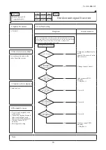
Page 87: ...Applicable model 5 Troubleshooting All models Diagnosis Countermeasure Aren t more than 17 indoor units connected to one remote control NO YES Remote control anomaly Replace it Reduce to 16 or less units 2 Error detection method When it detects more than 17 of indoor units connected to one remote control 3 Condition of error displayed Same as above 4 Presumable cause Excessive number of indoor uni...

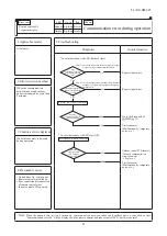
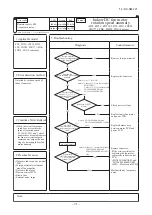
Page 88: ...ing the Master IU address set function of remote control 3 Condition of Error displayed Same as above 4 Presumable cause Same as above Note Is Master IU address set function of remote control used E11 occurs YES Error code Remote control LED Green Red Indoor Content IU IU IU R C In case the wiring is below and Master IU address set is used E11 is appeared Error code Remote control 7 segment displa...

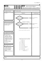
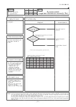
Page 89: ...displayed Same as above 4 Presumable cause Mistake in address setting for indoor unit Note Address setting method list Figures in are for Previous Superlink models Models for new Superlink protocol Models for Previous Superlink protocol Indoor unit address setting Outdoor unit address setting Indoor unit address setting Outdoor unit address setting Indoor unit No SW Outdoor unit No SW Outdoor unit...

Page 90: ...HFN SRZHU YROWDJH Replace faulty fan motor and power PCB 5HSODFH KDUQHVV DVV between motor PCB and power PCB Replace fan motor I WKH HUURU SHUVLVWV DIWHU UHSODFLQJ WKH IDQ PRWRU UHSODFH WKH LQGRRU FRQWURO PCB FDU224 280KXZE1 and FDU1800 2400FKXZE1 FM1 Motor contrl PCB Malfunction by temporary noise 2 UURU GHWHFWLRQ PHWKRG Detected by rotation speed of indoor fan motor Condition of Error displayed ...

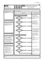
Page 91: ... NO NO YES YES YES Is the power surely supplied to the master indoor unit Is the address setting for the master indoor unit correct Correct the address setting of Supply the power to the master Connect the Superlink signal Indoor control PCB anomaly slave indoor unit If it is not the master indoor unit as well Are the Superlink signal wires connected between master and slave indoor units 1 When th...

Page 92: ...displayed Same as above 4 Presumable cause Mistake in SW7 1 setting Due to forgetting to turn OFF SW7 1 after indoor operation check Note Indoor operation check drain pump check mode If the power is ON after SW7 1ON indoor operation check drain pump check mode can be established 1 When the communication between remote control and indoor PCB is established 15 seconds after power ON it goes to indoo...

Page 93: ...ZHU YROWDJH Replace faulty fan motor and power PCB 5HSODFH KDUQHVV DVV between motor PCB and power PCB Replace fan motor I WKH HUURU SHUVLVWV DIWHU UHSODFLQJ WKH IDQ PRWRU UHSODFH WKH LQGRRU FRQWURO PCB FDU224 280KXZE1 and FDU1800 2400FKXZE1 FM1 Motor contrl PCB Malfunction by temporary noise 2 UURU GHWHFWLRQ PHWKRG Detected by rotation speed of indoor fan motor Condition of Error displayed KHQ WK...

Page 94: ...between panel PCB CNV Correct or replace wire Defective indoor control PCB Replace indoor control PCB 2 Error detection method Panel switch PS has detected Open for more than 1 second 3 Condition of Error displayed Same as above 4 Presumable cause Defective panel switch Disconnection of wiring Defective indoor control PCB Note Does matter improve if panel switch is turned ON forcibly after resetti...

Page 95: ...omaly occurs again within 60 minutes after the initial detection 4 Presumable cause Anomalous connection of remote control temperature thermistor Remote control temperature thermistor anomaly Remote control PCB anomaly Note After 10 seconds has elapsed since remote control temperature thermistor was switched from invalid to valid E28 will not be displayed even if the thermistor harness is disconne...

Page 96: ...ting is not damaged It was experienced that No 5 on rotary switch was not recognized 2 Error detection method When the microcomputer of outdoor control PCB recognizes the duplicated address No by scanning all addresses of outdoor units in the same Superlink system 3 Condition of error displayed When duplicated outdoor unit address No exists in the same Superlink system 4 Presumable cause Mistake i...

Page 97: ...her it occurs immediately after the power on or during operation or stopping It will be useful to persuade the customer why an improvement of power source is required by showing these data Propose an improvement to the customer Check it as much as possible under the operating conditions for 30 minutes before error occurred Replace outdoor control PCB Check the connection of wire Wait and see witho...

Page 98: ...icient or not Check the gas leakage Insert connector securely Check if the characteristics are correct by referring the characteristics chart of E39 And if necessary replace the discharge pipe temperature thermistor Check it as much as possible under the operating conditions for 30 minutes before error occurred Wait and see Continue to obtain data if possible Keep connecting the Mente PC Replace o...

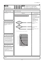
Page 99: ...the power on or during operation or stopping Check the sensed value Compare the temperature on Mente PC with actual measured value Insert the connector securely Replace thermistor Tho SC Tho H Tho R Replace outdoor control PCB 2 Error detection method Detection of anomalously low temperature resistance of Tho R or Tho SC or Tho H 3 Condition of error displayed If 50 C or lower is detected for 5 se...

Page 100: ...immediately after the power on or during operation or stopping Check the sensed value Compare the temperature on Mente PC with actual measured value Insert the connector securely Replace thermistor Tho A Replace outdoor control PCB 2 Error detection method Detection of anomalously low temperature resistance of Tho A 3 Condition of error displayed If 30 C or lower is detected for 5 seconds continuo...

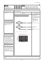
Page 101: ...ating condition Check the conditions whether it occurs immediately after the power on or during operation or stopping Check the sensed value Compare the temperature on Mente PC with actual measured value Insert the connector securely Replace thermistor Tho D Replace outdoor control PCB 2 Error detection method Detection of anomalously low temperature resistance of Tho D 3 Condition of error displa...

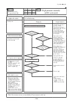
Page 102: ...lf according to the troubleshooting procedure of E54 after restarting operation If the high pressure sensor PSH fails replace it If the connector is disconnected or the harness is broken correct it Also check whether the high pressure switch is properly mounted or not Check the open N phase on power source Open operation valve Check it as much as possible under the operating conditions for 30 minu...

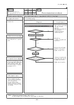
Page 103: ...Between and of C19 If it fails to repeat connect the Mente PC and continue to collect data 1 E41 1 E51 1 CM1 E41 2 E51 2 CM2 2 E41 1 E51 1 1 time flash E41 2 E51 2 2 time flash Check record operating condition Check power transistor temperature Check operations of outdoor fan inverter cooling fan Have outdoor fans been running Reset the power source and restart NO YES NO Does it repeat after resta...

Page 104: ...e if necessary Check record operating condition Check record operating condition Check pressure for anomaly Wait and see Replace compressor Wait and see Replace compressor on which error occurred initially Replace power transistor Replace power transistor Replace inverter PCB Save data for 30 minutes before stopping in Mente PC Evaluate data 30 minutes earlier YES YES YES YES YES YES NO NO NO NO P...

Page 105: ...ed indoor units exceeds the limitation if tentative operation is required turn ON the dip switch SW5 4 on the outdoor control PCB However since this tentative solution could cause trouble be sure to correct it as soon as possible Signal wire may be connected to other outdoor unit system Correct the signal wire Correct addresses Either one of addresses is wrong If the address corrected with rotary ...

Page 106: ...outdoor fan rotates Save data for 30 minutes before stopping in Mente PC NO NO NO NO NO NO NO YES YES YES YES YES YES YES Is the characteristics of Tho C OK Check and save the data of operating condition Check the ROM version Confirmation of SV1 operation Correct the connection of refrigerant piping and or signal wiring properly Adjust refrigerant amount properly Replace SV1 Replace the coil of SV...

Page 107: ...g condition Check under operating condition 30 minutes earlier than the error as much as possible Replace control PCB NO NO NO NO NO NO Isthereshort circuitorbrokenwirebetweendiodemodules YES NO NO YES Is green or red LED flashing or lighting on inverter PCB Save data for 30 minutes before stopping in Mente PC Power ON Is surge suppressor resistor coil broken Power OFF Power OFF YES YES YES NO YES...

Page 108: ...ecause it is judged that the power rest is not done after changing address Correct signal line In case of automatic address setting signal line cannot be connected to other outdoor unit system Test run Replace outdoor control PCB Rotary switch anomaly Before replacement please confirm whether the rotary switch for address setting is not damaged It was experienced that No 5 on rotary switch was not...

Page 109: ...e 2 Measurement position Between pins 2 3 of IC3 on control PCB If it fails to repeat connect the Mente PC and continue to collect data 1 1 time flash FMo1 2 time flash FMo2 Replace fan motor Replace inverter PCB on 1 line When inverter PCB is replaced check also items further than 3 see next page Checking of blown surge suppressor resister coil and short circuit on power transistor and diode Repl...

Page 110: ...tate of overcurrent is communicated 4 Presumable cause Broken or disconnected wire Faulty fan motor Defective inverter PCB Defective control PCB Defective power transistor Defective diode module Defective surge suppressor resistor Note 1 1 time flash FMo1 2 time flash FMo2 Power OFF From previous page Does speed command voltage of control PCB rise gradually and stabilize after a rise of several V ...

Page 111: ...e according to the piping length instructed on the label pasted on the panel of the unit Check whether the service valves are open Correct the connection of low pressure sensor connector Replace low pressure sensor Replace outdoor control PCB Correct the connection of temperature thermistor connector of heat exchanger Replace temperature thermistor of heat exchanger at evaporator side Replace cont...

Page 112: ...utes to 2 minutes 20 seconds after compressor ON compressor stops When the compressor is restarted automatically after 3 minutes delay if this anomaly occurs 3 times within 40 minutes 4 Presumable cause Broken thermistor harness or the internal wire of sensing section Check the molded section as well Disconnection of thermistor harness connection connector Outdoor control PCB anomaly Note 1 E53 Th...

Page 113: ...easure by pressure gauge YES Output voltage V Output voltage V Check and save the data of operating conditions Check the conditions whether it occurs immediately after the power on or during operation or stopping Check the sensed value Insert the connector securely and restart operation Temporary malfunction by noise Correct if the source of noise is specified Replace sensor PSH PSL Replace outdoo...

Page 114: ...nits Evaluate data 30 minutes earlier Turn power ON after 1 hour if possible and operate again Change wire connections on inverter and compressor and operate again Is it initial startup within 1 hour after power ON Is there record of replacement of inverter PCB Is DC 15 V detected on inverter PCB Check inverter PCB for defect with the checker Other Including checker not available Power transistor ...

Page 115: ... change over to the operation for rotor position detection of compressor motor If the compressor speed cannot increase 11rps or higher 3 Condition of error displayed If the compressor fails to startup for 20 times 10 patterns x 2 times continuously 4 Presumable cause Anomalous voltage of power source Anomalous components for refrigerant circuit Inverter PCB anomaly Loose connection of connector or...

Page 116: ...nte PC YES NO NO YES Check and save the data of operating conditions Check the conditions whether it occurs immediately after the power on or during operation Replace remote control PCB Replace indoor unit control PCB Check the cause of emergency stop It is better to have the data for 30 minutes before stopping when instructing the installer 2 Error detection method When ON signal is inputted to t...

Page 117: ... which will result in death or serious injury if proper safety procedures and instructions are not adhered to Indicates a potentially hazardous situation which may result in minor or moderate injury if proper safety procedures and instructions are not adhered to WARNING Securely exchange the PCB according to this procedure If the PCB is incorrectly exchanged it will cause an electric shock or fire ...

Page 118: ...KX SM 221 115 14 KX SM 221 Fig 2 Voltage measurement point After elapsing 3 minutes from power OFF Connectors are not half inserted Control PCB voltage measurement point DC Target PCB Pin terminals 1 3 of CNA1 ...

Page 119: ...psing 3 minutes from power OFF 2 In the situation that harnesses are connected to control PCB be sure to measure voltage DC of two places A B and check that the voltage is discharged sufficiently Refer to Fig 2 3 Remove the harnesses from bands clips and connectors on the control PCB Then remove the appointedscrews 4 places of a controller Refer to Fig 3 4 Open main layer and measure voltage DC of...

Page 120: ...resence and shape of electric component may vary according to a model or or Fig 3 Target places which are removed harnesses and screws Remove screws 4 places Remove harnesses from bands And remove the harnesses which are bundled by these bands from clips and connectors on the control PCB Presence and shape of electric component may vary according to a model Control PCB ...

Page 121: ... is set in each hole of the inverter PCB of P N U V and W beforehand Then tighten the harness Snubber capacitor and the power transistor with the screw together Set the harness wires to be fixed to U and W with screws in respective holes after passing them through IC21 and 22 Connect the snubber capacitor with P and N Fig 5 Installation method to power transistor Harness Inverter PCB Connection bi...

Page 122: ... PCB exchange under current carrying will cause an electric shockor fire After finishing the PCB exchange check that wiring is correctly connected with the PCB before power distribution If the PCBis incorrectly exchanged it will cause an electric shock or fire CAUTION Band the wiring so as not to tense because it will cause an electric shock Exchange the converter PCB according to the following pr...

Page 123: ... 121 14 KX SM 221 Fig 2 Voltage measurement points Target PCB Voltage measurement points Pin terminals 1 3 of CNA3 ...

Page 124: ...m WARNING and CAUTION are described as follows WARNING Indicates an imminently hazardous situation which will result in death or serious injury if proper safety procedures and instructions are not adhered to CAUTION Indicates a potentially hazardous situation which may result in minor or moderate injury if proper safety procedures and instructions are not adhered to WARNING Securely exchange the t...

Page 125: ...s injury if proper safety procedures and instructions are not adhered to CAUTION Indicates a potentially hazardous situation which may result in minor or moderate injury if proper safety procedures and instructions are not adhered to WARNING Securely exchange the diode module according to this procedure If the diode module is incorrectly exchanged it will cause an electric shock or fire Be sure to...

Page 126: ...ermistor 2 CT1 Current sensor CM1 PSH CNL1 High pressure sensor PSL CNL2 Low pressure sensor 63H1 CHQ1 High pressure switch CM1 CNS1 External operation input Power source CNW 380 415V Open phase detection Mark Connector Function 52X2 CNM1 Solenoid for CM1 20S CNN1 4 way valve SV6 CNN3 Solenoid valve oil return CM1 SV1 CNN8 Solenoid valve CM1 liquid bypass CH1 CNR1 Crankcase heater CM1 CNZ1 Externa...

Page 127: ... Mark CH Mark CM CNA Z CT1 DM Crankcase heater Compressor motor Connector Current sensor Diode module Part name Meaning of marks C1 2 Capacitor F FMo 1 2 IPM L PSL Fuse Fan motor Intelligent power module Reactor Low pressure sensor EEVSC EEVH Expansion valve for SC Expansion valve for heating Solenoid coil for 4 way valve Relay High pressure switch PSH High pressure sensor J10 Super link terminal ...

Page 128: ...ing coil Gas line Liquid line Strainer Electronic expansion valve Strainer To next indoor units Thi R2 Thermistor Entrance Thi A Thermistor Thermistor Exit Thi R3 Thermistor Bend Thi R1 Thi R2 Thermistor Thi A Thermistor Entrance Thi R3 Heat exchanger Outdoor unit Indoor unit Electronic expansion valve EEVSC Highpressure sensor PSH 4way valve 20S Sub cooling coil Thermistor Tho SC Tho C1 Thermisto...

Page 129: ...n carrying the unit by hand If the unit weights more than 20kg it must be carried by two or more persons Do not carry by the plastic straps always Dispose of any packing materials correctly Any remaining packing materials can cause personal injury as it contains nails and wood And to avoid danger of suffocation be sure to keep the plastic wrapper away from children and to dispose after tear it up ...

Page 130: ...dicated R410A tools Do not use any refrigerant other than R410A R410A will rise to pressure about 1 6 times higher than that of a conventional refrigerant A unit designed for R410A has adopted a different size outdoor unit service valve charge port and a different size check joint provided in the unit to measurement have also been altered to raise strength against pressure Accordingly you are requ...

Page 131: ...for ø15 88 or less Wall thickness and size Select according to the guide for pipe size selection This product uses R410A Since in case of pipes in the size of ø19 05 or more materials of O thickness larger than the minimum thickness When a pipe is branched make sure to use our branching set or header set When setting branching pipes take care of the mounting direction and consult carefully with th...

Page 132: ...For ø19 05 or larger use C1220T 1 2H material Total capacity downstream Less than 180 180 or more Branch pipe set DIS 22 1G DIS 180 1G c Between branching at indoor unit side indoor unit side Section C in Fig 1 According to the table of pipe size for indoor unit However it should never exceed the size of main pipe Section A in Fig 1 4 Selection of the branch set for indoor unit side a Selection of...

Page 133: ...nt H mm φ6 35 φ9 52 φ12 7 φ15 88 Copper pipe outer diameter H 17 22 26 29 A B Flared pipe end A mm φ6 35 φ9 52 φ12 7 φ15 88 Copper pipe outer diameter 0 0 4 A 9 1 13 2 16 6 19 7 φ6 35 φ9 52 φ12 7 φ15 88 Copper pipe outer diameter In the case of a rigid clutch type With an R410A tool With a conventional tool 0 0 5 0 7 1 3 CAUTION If you tighten it without using double spanners you may deform the ou...

Page 134: ...essure drops b to see if the pressure drops d If no pressure drop is observed with an installation pressurized to and left for about one day it is acceptable When the ambient temperature changes 1 the pressure also changes approximately 0 01 MPa The pressure if changed should be compensated for After repair conduct an air tightness test again Always pull air from the pipes after the airtightness t...

Page 135: ...52 0 054 ø6 35 0 022 Remark 6 2 6 1 6 El 5 DR Additional charge quantity for piping P kg L1 0 054 L2 0 022 If P 1 6kg Important Total additional charge quantity P kg If P 1 6kg Total additional charge quantity P kg 1 0 kg Charge quantity for the refrigerant piping SSA011H003 gases covered by the Kyoto Protocol Ce produit contient des gaz à effets de serre Treibhausgase die unter das Kyoto Protokol...

Page 136: ... an impulse withstanding type earth leakage breaker is necessary turn on the power until the electrical work is completed Be sure to turn off the power when servicing g Do not use a condensive capacitor for power factor improvement under any circumstances It does not improve power factor while it can cause an abnormal overheat accident h For power source cables use conduits i Do not lay electronic...

Page 137: ...rd resistance value 46 000 Number of connected FD A KXE4 and 5 Series units x 5 Number of connected FD KXE6 and KXZ Series units x 9 The number of connected units includes those of indoor units outdoor units and SL devices If the resistance value is less than 100Ω disconnect the signal cables temporarily to divide to more than one network to reduce the number of indoor units on the same network an...

Page 138: ...Manual 7 CONTROL SETTINGS Case 1 Case 2 When signal lines linking plural refrigerant systems are provided between outdoor units When the network connector is disconnected refrigerant systems are separated each other When signal lines linking plural refrigerant systems are provided between indoor units When only one refrigerant system is involved signal lines do not link plural refrigerant systems ...

Page 139: ...ting previous SL new SL Units supporting new SL Units NOT supporting new SL SW1 SW3 SW2 SW4 For ten s place For one s place precision screw driver into this groove and turn the arrow to point a desired number Indoor PCB Outdoor PCB SW1 2 blue SW3 4 green SW5 2 SW1 2 green For setting indoor No The ten s and one s For setting outdoor No The ten s and one s Indoor No switch The hundred s Place OFF 0...

Page 140: ...e minute or longer interval for them Select and enter 1 in P31 on the 7 segment display panel of each outdoor unit to input Automatic address start Input a starting address and the number of connected indoor units Input a starting address in P32 on the 7 segment display panel of each outdoor unit When a starting address is entered the display indication will switch back to the Number of Connected ...

Page 141: ...re controlled from one remote control unit Once they are registered addresses are stored in microcomputers even if power is turned off If you want to change an address after automatic address setting you can change it from the remote control unit with its Address Change function or by means of manual setting Set a unique address by avoiding the address assigned to other indoor unit on the network ...

Page 142: ...fter the addresses are determined Turning on power in wrong order may result in a failure to recognize addresses Item Operation Display NOTICE 7 segment display indication in automatic address setting Code Contents of a display P30 P31 P32 P34 Code Contents of a display Unable to find any indoor unit that can be actually communicated with The number of the indoor units that can be actually communi...

Page 143: ... Operation priority selection SW4 7 OFF SW4 8 OFF 1 80 Factory default SW4 7 ON SW4 8 OFF 1 60 SW4 7 OFF SW4 8 ON 1 40 SW4 7 ON SW4 8 ON 1 00 ー ー ー ー ー ー ー ー ー ー ー ー Close the liquid operation valve on outdoor unit and set as follows 1 SW5 2 on PCB to ON 2 SW5 3 on PCB to ON 3 SW5 1 on PCB to ON Forced cooling heating mode Set allocation of external input function to 2 1 Set allocation of external...

Page 144: ... demand ratio If peak cut signals are received from two or more indoor units it is operated with the lowest demand ratio Note If two or more settings of 1 and 2 above are established simultaneously the priority is given to the demand of lowest ratio If the settings of the silent mode and the demand control are established simultaneously they are operated according to their lowest demands SW4 7 SW4...

Page 145: ...re to braze while supplying nitrogen gas If no nitrogen gas is supplied a large amount of impurity oxidized film will be generated which may clog the capillary tube and the expansion valve resulting in fatal malfunction Table 2 Parts used for the connecting pipe assembly Table 1 Pipe specification m h t g n e l y a w e n o e n i l t n a r e g i r f e R φ 22 22 x T1 0 φ 25 4 x T1 0 orφ 28 58 x T1 0...

Page 146: ...e Elbow procured in the field Straight pipe Procured in the field 105mm or more Connection example of refrigerant pipe Ⓐ Downward connection Connection example of refrigerant pipe Ⓑ Forward connection 40 80 26 69 Internal face of base Internal face of base Internal face of base Internal face of base Operation valve connecting position at gas side Operation valve connecting position at gas side Acc...

Page 147: ...58 IDφ25 4 IDφ28 58 IDφ25 4 344 479 125 IDφ12 7 IDφ22 22 IDφ12 7 IDφ19 05 IDφ15 88 IDφ12 7 DOS 3A 3 Branch pipe 1 Branch pipe 2 Branch pipe 1 Branch pipe 2 618 673 218 IDφ25 4 IDφ28 58 IDφ31 75 IDφ28 58 IDφ38 1 IDφ38 1 344 479 125 IDφ12 7 IDφ22 22 IDφ12 7 IDφ19 05 IDφ15 88 IDφ12 7 534 774 164 IDφ22 22 IDφ19 05 IDφ15 58 IDφ12 7 IDφ12 7 IDφ9 52 IDφ19 05 458 563 220 IDφ31 75 IDφ28 58 IDφ38 1 IDφ28 58...

Page 148: ...pipe set or a different diameter joint with a pipe cutter to make it fit for a selected pipe size before application Attention In cutting pipes always use a pipe cutter Remove burrs from a cut end when you cut a pipe In doing so keep a cut end downward so that no chips or burrs may enter the pipe Take utmost care so that no foreign matter such as dust or water may enter piping during installation ...

Page 149: ...owever select DIS 22 1G Even if the capacity of connected indoor units reaches 180 or higher select DIS 22 1G Total capacity downstream Branching pipe set model type less than 180 DIS 22 1G 180 or higher less than 371 DIS 180 1G 371 or higher less than 540 DIS 371 1G 540 or more DIS 540 3 Attention Use a pipe conforming to a pipe size specified for indoor unit connection for the section between an...

Page 150: ...112 224 36 80 56 160 45 28 56 140 1394 DIS 540 3 Branch pipe 2 Combined total capacity of indoor units connected downstream 140 160 90 45 112 224 36 80 56 160 45 28 56 140 1372 DIS 540 3 Branch pipe 3 Combined total capacity of indoor units connected downstream 112 224 36 80 56 160 45 28 56 140 937 DIS 540 3 Branch pipe 4 Combined total capacity of indoor units connected downstream 224 36 80 56 16...

Page 151: ...g Refrigeration Division 16 5 Konan 2 chome Minato ku Tokyo 108 8215 Japan http www mhi co jp Because of our policy of continuous improvement we reserve the right to make changes in all specifications without notice Copyright MITSUBISHI HEAVY INDUSTRIES LTD c ...

Reviews: