-
33
-
'09•KX-T-139
Outdoor unit
Outdoor unit
Floor surface
Floor surface
downward
branch
Floor surface
Liquid side
Horizontal
Floor surface
Floor surface
Gas side
Floor surface
Drain pipe
D (left)
720
80
175
D (right)
C (right)
172
95
90
C (rear)
F
166
44.7
20
86.5
220 180
550
180 214
D (front)
B
G
A
C (front)
1350
1690
[
2048
]
797.8
[
1155.8
]
682
166
169
259
211
291.6
84
6
104.9
86.1
6
126.2
The positions of connections on a base
Rear side
E
C
10
1
12
0
185
80.5
Dimensions of a refrigerant pipe
connection port (plan)
Rear side
B
G
A
95
14
1
14
0.5
75
142.5
234
7-segment
inspection port
Signal wire
terminal block
Terminal block
for power cable
connection
●
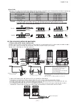
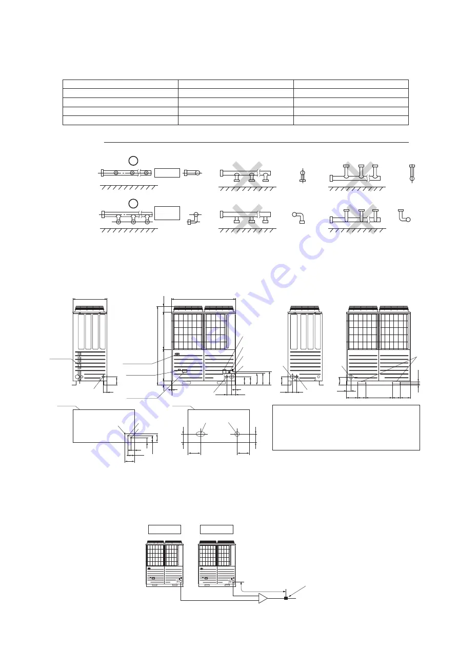
A pipe can be laid through the front, right, bottom or rear of a unit as illustrated on the above drawings.
●
In laying pipes on the installation site, cut off the casing’s half blank (
φ
88 or
φ
100) that covers a hole for pipe penetration with nippers.
●
When there is a danger that a small animal enters from the pipe port, cover the port with appropriate blocking materials (to be arranged on the user’s part).
●
Use an elbow (to be arranged on the user’s part) to connect control valves to the piping.
●
In anchoring piping on the installation site, give 1.5m or a longer distance between an outdoor unit and an anchoring point where the piping is secured as
illustrated below. (A failure to observe this instruction may result in a pipe fracture depending on a method of isolating vibrations employed.)
Although this drawing illustrates an installation involving a 450 or smaller capacity unit, an installation involving a 504 or a larger capacity unit should be arranged in
the same manner as long as pipe connection points and directions are concerned, except that the height of a unit is different.
Measurements in [ ] indicate those of a 504 or larger capacity unit.
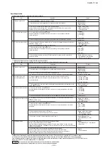
4-2. Pipe connection position and pipe direction
Over 1.5m
Pipe fastening position
Total capacity downstream
Less than 180
180 or more but less than 371
371 or more but less than 540
540 or more
Header set model type
HEAD4-22-1
HEAD6-180-1
HEAD8-371-1
HEAD8-540-2
Number of branches
4 branches at the most
8 branches at the most
8 branches at the most
8 branches at the most
(b) Header Method
●
Depending on the number of units connected, connect plugged pipes (to be procured on the installer’s part) at a branching point (on the indoor unit connection side).
●
For the size of a plugged pipe, please refer to the documentation for a header set (optional part).
Please note
a) In connecting a header with an indoor unit, please use a pipe conforming to the pipe size specified for indoor unit connection.
b)
In installing a header, always arrange a gas-side header to branch horizontally and a liquid-side header to branch downward.
c) Indoor units 224 and 280 can not be connected to the header.
An oil equalizing pipe must be connected only when an outdoor unit is used in a
combined installation.
(When a unit is used as a standalone installation, do not connect it)
A: Opening for refrigerant gas pipe connection
B: Opening for refrigerant liquid pipe connection
C: Refrigerant pipe port (
φ
88 or
φ
100)
D: Power cable port (
φ
50)
E: Power cable port (oblong hole measuring 40x80)
F: Holes for hoisting slings
G: Opening for oil equalizing pipe connection
Explanatory marks
(1) Pipe connecting position and pipe outgoing direction
Summary of Contents for FDCH1010CKXE6G
Page 8: ... 09 KX T 139 2 2 Exterior dimensions Models FDCH335CKXE6G K 400CKXE6G 450CKXE6G PCB003Z141 ...
Page 9: ... 09 KX T 139 Models FDCH504CKXE6G 560CKXE6G 560CKXE6G K 615CKXE6G 680CKXE6G PCB003Z142 ...
Page 10: ... 09 KX T 139 2 3 Electrical wiring Models All model PCB003Z139 ...
Page 41: ......
Page 42: ... 40 09 KX T 139 ...
Page 63: ... 09 KX T 139 Combination use PCB003Z587 61 ...
Page 64: ... 09 KX T 139 2 2 Exterior dimensions Models FDCH335CKXE6G K 400CKXE6G 450CKXE6G PCB003Z589 62 ...
Page 65: ... 09 KX T 139 Models FDCH504CKXE6G 560CKXE6G 560CKXE6G K 615CKXE6G 680CKXE6G PCB003Z590 63 ...
Page 66: ... 09 KX T 139 2 3 Electrical wiring Models All model PCB003Z588 64 ...


