-
42
-
'09•KX-T-139
ON
Automatic address setting Generally applicable to new SL/previous SL, use figures in [ ] with previous SL.
With new SL, you can set indoor unit addresses automatically even for an installation involving multiple refrigerant systems connected with same network, in addition to the conventional automatic
address setting of a single refrigerant system installation.
However, an installation must satisfy some additional requirements such as for wiring methods, so please read this manual carefully before you carry out automatic address setting.
(1) In the case of a single refrigerant system installation
(Generally applicable to new SL/previous SL, use figures in [ ] with previous SL.)
①
Outdoor unit address setting
Set as follows before you turn on power.
Make sure that the
Outdoor Unit No. switch
is set to
49 (factory setting).
②
Indoor unit address setting
Set as follows before you turn on power.
Make sure that the
Indoor Unit No. switch
is set to
000 [in the case of previous SL: 49] (factory setting).
Make sure that the
Outdoor Unit No. switch
is set to
49 (factory setting).
③
Turn on power in order from the outdoor unit to indoor units. Give a one-minute or longer interval for them. Unlike the procedure set out in (2) below, you need not change settings from the 7
segment display panel.
④
Make sure that the number of indoor units indicated on the 7 segment display panel agrees with the number of the indoor units that are actually connected to the refrigerant system.
(2) In the case of a multiple refrigerant systems installation
(Applicable to new SL only. In the case of previous SL, set addresses with some other method.)
(This option is available when the interconnection wiring among refrigerant systems is on the outdoor side and new SL is chosen as the communication protocol.)
②
Indoor unit address setting
Set as follows before you turn on power.
Make sure that the
Indoor Unit No. switch
is set to
000 (factory setting).
Make sure that the
Outdoor Unit No. switch
is set to
49 (factory setting).
③
Isolate the present refrigerant system from the network.
Disengage the
network connectors (white 2P)
of the outdoor units. (Turning on power without isolating each refrigerant system will result in erroneous address setting.)
[STEP2]
(Power on and automatic address setting)
④
Turn on power to the outdoor unit
Turn on power in order from the outdoor unit to indoor units. Give a one-minute or longer interval for them.
⑤
Select and enter “1” in P31 on the 7 segment display panel of each outdoor unit (master unit in case of combination) to input “Automatic address start.”
⑥
Input a starting address and the number of connected indoor units.
Input a starting address in P32 on the 7 segment display panel of each outdoor unit (master unit in case of combination).
⑦
When a starting address is entered, the display indication will switch back to the “Number of Connected Indoor Units Input” screen.
Input the number of connected indoor units from the 7 segment display panel of each outdoor unit (master unit in case of combination). Please input the number of connected indoor units (on
the same refrigerant line in case of combination) for each outdoor unit. (You can input it from P33 on the 7 segment display panel.)When the number of connected indoor units is entered, the 7
segment display panel indication will switch to “AUX” and start flickering.
[STEP3]
(Automatic address setting completion check)
⑧
Indoor unit address determination
When the indoor unit addresses are all set, the 7 segment display panel indication will switch to “AUE” and start flickering.
If an error is detected in this process, the display will show “A
○○
.”
Check the 7 segment display panel of each outdoor unit (master unit in case of combination).
Depending on the number of connected indoor units, it may take
about 10 minutes
before the indoor unit addresses are all set.
[STEP4]
(Network definition setting)
⑨
Network connection
When you have confirmed an “AUE” indication on the display of each outdoor unit,
engage the network connectors
again.
⑩
Network polarity setting
After you have made sure that the network connectors are engaged
in
⑧
, select and enter “1” in P34 on the 7 segment display panel of
any outdoor unit (on only 1 unit : master
unit in case of combination)
to specify network polarity.
⑪
Network setting completion check
When the network is defined, “End” will appear on the 7 segment display panel. An “End” indication will go off, when some operation is made from the 7 segment display panel or
3 minutes after.
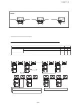
Address setting procedure
(perform these steps for each outdoor unit)
[STEP1]
(Items set before turning on power)
①
Outdoor unit address setting
Set as follows before you turn on power.
Set
the Outdoor Unit No. switch
to a number
00 - 31
. Set a unique number by avoiding the numbers assigned to other outdoor units on the network.
-
Similarly for the master unit used in a combined installation, make sure that the Outdoor unit No. switch is set to 49 (factory setting).
-
Similarly for the slave unit used in a combined installation, make sure that the Outdoor unit No. switch is set to 49 (factory setting).
Then, set the dipswitch SW4-7 of the slave unit to ON.
SW4-7
Address on a network
OFF
49
00
SW2
9
9
SW1
4
4
Outdoor unit
Master unit
Slave unit
The
master unit
will be registered as
“49”
regardless of the SW1 and SW2 settings (49).
The
slave unit
will be registered as
“00”
because of its SW4-7 setting as indicated in the table above.
CAUTION
If the slave unit is not specified, a
compressor failure may result.
●
Similarly for the master unit used in a combined installation, set
the Outdoor Unit No. switch to a number 00-31.
●
Similarly for the slave unit used in a combined installation, set
the Outdoor Unit No. switch to the same number with a master unit and then, set the dipswitch SW4-7 of the slave
unit to ON.
(Set both master and slave units on the same outdoor unit number.)
Summary of Contents for FDCH1010CKXE6G
Page 8: ... 09 KX T 139 2 2 Exterior dimensions Models FDCH335CKXE6G K 400CKXE6G 450CKXE6G PCB003Z141 ...
Page 9: ... 09 KX T 139 Models FDCH504CKXE6G 560CKXE6G 560CKXE6G K 615CKXE6G 680CKXE6G PCB003Z142 ...
Page 10: ... 09 KX T 139 2 3 Electrical wiring Models All model PCB003Z139 ...
Page 41: ......
Page 42: ... 40 09 KX T 139 ...
Page 63: ... 09 KX T 139 Combination use PCB003Z587 61 ...
Page 64: ... 09 KX T 139 2 2 Exterior dimensions Models FDCH335CKXE6G K 400CKXE6G 450CKXE6G PCB003Z589 62 ...
Page 65: ... 09 KX T 139 Models FDCH504CKXE6G 560CKXE6G 560CKXE6G K 615CKXE6G 680CKXE6G PCB003Z590 63 ...
Page 66: ... 09 KX T 139 2 3 Electrical wiring Models All model PCB003Z588 64 ...

