-
47
-
'09•KX-T-139
(1)
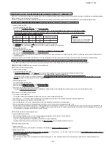
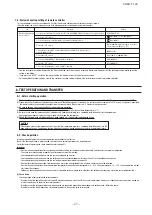
Make sure that a measurement between the power supply terminal block and ground, when measured with a 500V megger, is greater than 1 M
Ω
.
(2) Please check the resistance of the signaling wire terminal block before power is turned on. If a resistance measurement is 100
Ω
or less, it suggests a possibility
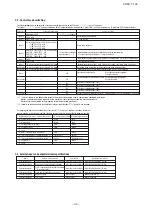
that power cables are connected to the signaling wire terminal block. (Please refer to 6-3. Standard resistance valve.)
(3)
Be sure to turn on the crank case heater 6 hours before operation
.
(4)
Make sure that the bottom of the compressor casing is warm
. (higher than outdoor tempe5°C)
(5) Be sure to fully open the operation valves (liquid,gas and Equalizen oil piping (for a combined installation only)) for the outdoor unit.
Operating the outdoor unit with the valves closed may damage the compressor.
(6)
Check that the power to all indoor units has been turned on. If not, water leakage may occur
.
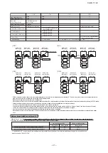
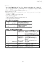
It is recommended to practice the check operation in precedent to the test run.
[Even if the check operation is not practiced, the test run and normal operations can be performed.]
For further details regarding the check operation refer to page 52.
・
Practice the check operation after completing the address setting for the indoor and outdoor units and also after charging the refrigerant.
・
To assure accurate checking, proper amount of refrigerant must be retained.
・
Check operation cannot be done when the system is stopped by an error.
・
Check operation cannot be done when the total capacity of connected indoor units is less than 80% of the outdoor unit capacity.
・
Check operation cannot be done when the system communication method is previous SL.
・
Don’t perform the check operation simultaneously on more than one refrigerant line. Accurate checking cannot be obtained.
・
Practice the check operation within the operation temperature ranges (Outdoor temperature: 0 – 43°C, room temperature: 10 – 32°C). Check operation will not
start out of these ranges.
・
Outdoor air processing unit cannot be checked. (It is possible to check indoor units other than the outdoor air processing unit of the same refrigerant line.)
CAUTION
Please make sure that the operation valves (gas, liquid, oil equalizing pipe (for a combined installation only)) are full
open before a test run. Conducing a test run with any of them in a closed position can result in a compressor failure.
8. TEST OPERATION AND TRANSFER
8-1. Before starting operation
8-2. Check operation
Important
Check operation allows proving the following points.
・
Whether or not the operation valve is left open (Operation valve open/close check). (In case of combination, however, all operation valves need to be closed on
master and slave units to obtain accurate judgment.)
・
Whether or not the refrigerant pipes and signal cables are connected properly between indoor and outdoor units. (Mismatch check)
・
Whether or not the indoor expansion valve operates properly. (Expansion valve failure check)
(1) Check items
⑦
Select the “COOLING ONLY“ by pressing
▲
or
▼
switch.
④
Press the “SET” switch.
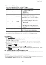
Item
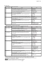
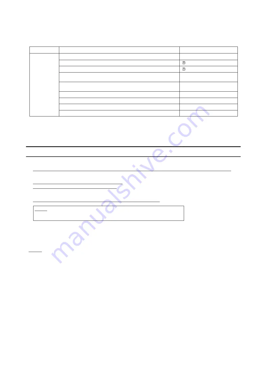
7-4. Exclusive cooling setting of remote controller
Function setting of wired
remote controller
①
Stop the air-conditioner. Then press the “SET” and “OPERATION SELECT” switches for 3 seconds or longer.
②
Press the “SET” switch.
Operation
Display
③
Select the “Remote control function
▼
” by pressing the
▲
or
▼
switch.
⑤
Press the
▲
or
▼
switch. (Function and number are displayed one after the other.)
Select the “MODEL TYPE”.
⑥
Press the “SET” switch.
⑧
Press the “SET” switch.
⑨
Press the “Operation/Stop” switch. Setting is completed.
[FUNCTION SET
▼
]
[ FUNCTION
▼
] or [I/U FUNCTION
▼
]
[ FUNCTION
▼
]
[DATA LOADING] (Flashes for approx. 2 seconds.)
Then it changes to [GRILLE
↑↓
SET] .
[MODEL TYPE]
[HEAT PUMP] or [COOLING ONLY]
[COOLING ONLY]
[SET COMPLETE]
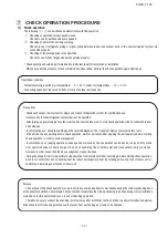
This air-conditioner is an exclusive cooling unit. Set it for the exclusive cooling using the remote controller as follows.
(After this setting, the unit will not operate even if the heating operation is selected on the remote controller.)
・
You can terminate the setting by pressing the “Operation/Stop” switch on the way of setting. Please note, however, that the setting becomes invalid unless the
setting is completed.
・
If you press the “RESET” switch on the way of setting, the display returns to the last previous screen.
・
For further details of other settings, refer to the section of function setting included in the installation manual of the remote controller.
Summary of Contents for FDCH1010CKXE6G
Page 8: ... 09 KX T 139 2 2 Exterior dimensions Models FDCH335CKXE6G K 400CKXE6G 450CKXE6G PCB003Z141 ...
Page 9: ... 09 KX T 139 Models FDCH504CKXE6G 560CKXE6G 560CKXE6G K 615CKXE6G 680CKXE6G PCB003Z142 ...
Page 10: ... 09 KX T 139 2 3 Electrical wiring Models All model PCB003Z139 ...
Page 41: ......
Page 42: ... 40 09 KX T 139 ...
Page 63: ... 09 KX T 139 Combination use PCB003Z587 61 ...
Page 64: ... 09 KX T 139 2 2 Exterior dimensions Models FDCH335CKXE6G K 400CKXE6G 450CKXE6G PCB003Z589 62 ...
Page 65: ... 09 KX T 139 Models FDCH504CKXE6G 560CKXE6G 560CKXE6G K 615CKXE6G 680CKXE6G PCB003Z590 63 ...
Page 66: ... 09 KX T 139 2 3 Electrical wiring Models All model PCB003Z588 64 ...

