-
48
-
'09•KX-T-139
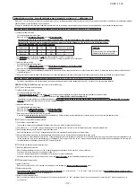
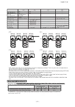
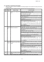
Error display on 7-segment indicator after ending the check operation
Code indicato
Data indicator
Display contents
Check following points
CHL
CHU
CHJ
CHE
CHE
Operation valve is closed.
(Refrigerant circuit is shut off
partially.)
・
Isn’t the operation valve of outdoor unit left open?
・
Is the low pressure sensor normal? (Detected pressure can be seen on
the 7-segment indicator.)
・
Is the connector of indoor unit expansion valve coil connected?
・
Isn’t the indoor unit expansion valve coil disconnected from the
expansion valve body?
・
Is the indoor unit heat exchanger sensor normal? (Check if the sensor is
disconnected.)
Mismatch between
refrigerant pipes and signal
cables. Refrigerant is not
circulated to the indoor unit of
which No. is displayed.
・
Are the refrigerant pipes and signal cables connected properly between
the indoor and outdoor units?
・
Is the connector of indoor unit expansion valve coil connected?
・
Isn’t the indoor unit expansion valve coil disconnected from the
expansion valve body?
・
Is the indoor unit heat exchanger sensor normal? (Check if the sensor is
disconnected.)
Expansion valve on the indoor
unit of which No. is displayed
is not operating properly.
・
Is the connector of indoor unit expansion valve coil connected?
・
Isn’t the indoor unit expansion valve coil disconnected from the
expansion valve body?
・
Is the indoor unit heat exchanger sensor normal? (Check if the sensor is
disconnected.)
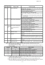
Abnormal ending of check
operation.
・
Isn’t any error displayed (E??) on the indoor unit or outdoor unit?
・
Are signal cables connected without play?
・
Hasn’t the SW setting been changed during the check operation?
Abnormal ending of check
operation. Indoor unit of which
No. is displayed is abnormal.
・
Isn’t any error displayed (E??) on the indoor unit or outdoor unit?
・
Are signal cables connected without play?
・
Is the power supply to the indoor unit turned on?
※
When any error is detected, errors other than those listed above may be displayed. In such occasion, refer to page 56.
Abnormal indoor unit No.
Abnormal indoor unit No.
Abnormal indoor unit No.
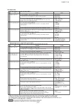
Display on 7-segent indicator during check operation
(a) Starting the check operation
・
Confirm that all of the following switches are turned OFF: SW3-2 (Auto backup operation), SW3-6 (Pipe wash mode), SW3-7 (Forced cooling/heating mode),
SW5-1 (Test run), SW5-2 (Test run cooling setting), SW5-3 (Pump-down operation) and SW5-6, -7, -8 (Capacity measurement mode). (In case of combination, on
both main and slave units)
・
At the next, turn the SW3-5 (Check operation) OFF
¡
ON (only on master unit in case of combination) so that the check operation will start.
・
It takes 15 – 30 minutes normally (max. 80 min) from the start to the end of check operation.
(b) End the check operation and the result display
・
When the check operation is over, the system stops automatically. The 7-segment indicator shows the result (only on master unit in case of combination).
<Normal ending>
・
7-segment indicator shows “CHO End”.
・
Return the SW3-5 to OFF. The 7-segment indicator returns to normal display.
・
Return SW3-7 (Forced cooling/heating mode) to ON.
<Abnormal ending>
・
7-segment indicator shows an error alarm.
・
Referring to the section [Inspect here], repair the faulty section and return the SW3-5 to OFF.
・
At the next, repeat the check operation from the Step (2) above.
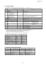
(2) Method of check operation
Code indicato
Data indicator
Display contents
Max. remaining time
Max. remaining time
H1
H2
HO
CHO
End
Check operation preparation on. Indicates max. remaining time (min).
(In case of combination, indicated on master unit only.)
Check operation on. Indicates max. remaining time (min).
(In case of combination, indicated on master unit only.)
Check operation on. (Including preparation operation on).
(Indicated only on slave unit of combination.)
Normal ending of check operation.
(In case of combination, indicated on master unit only.)
Summary of Contents for FDCH1010CKXE6G
Page 8: ... 09 KX T 139 2 2 Exterior dimensions Models FDCH335CKXE6G K 400CKXE6G 450CKXE6G PCB003Z141 ...
Page 9: ... 09 KX T 139 Models FDCH504CKXE6G 560CKXE6G 560CKXE6G K 615CKXE6G 680CKXE6G PCB003Z142 ...
Page 10: ... 09 KX T 139 2 3 Electrical wiring Models All model PCB003Z139 ...
Page 41: ......
Page 42: ... 40 09 KX T 139 ...
Page 63: ... 09 KX T 139 Combination use PCB003Z587 61 ...
Page 64: ... 09 KX T 139 2 2 Exterior dimensions Models FDCH335CKXE6G K 400CKXE6G 450CKXE6G PCB003Z589 62 ...
Page 65: ... 09 KX T 139 Models FDCH504CKXE6G 560CKXE6G 560CKXE6G K 615CKXE6G 680CKXE6G PCB003Z590 63 ...
Page 66: ... 09 KX T 139 2 3 Electrical wiring Models All model PCB003Z588 64 ...

