-
50
-
'09•KX-T-139
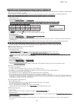
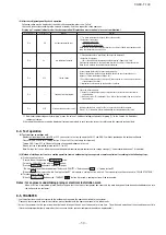
(2) Method of starting a test run for a cooling operation from an outdoor unit: please operate a remote control unit according to the following steps.
(a) Start of a cooling test run
○
Operate the unit by pressing the START/STOP button.
○
Select the “COOLING” mode with the MODE button.
○
Press the TEST RUN button for 3 seconds or longer.
The screen display will be switched from “Select with ITEM ”
→
“Determine with SET ”
→
“Cooling test run
▼
.”
○
When the SET button is pressed while “Cooling test run
▼
” is displayed, a cooling test run will start. The screen display will be switched to “COOLING TEST RUN.”
(b) Termination of a cooling test run
○
When the START/STOP button or the “TEMP SET ” button is pressed, a cooling test run will be terminated.
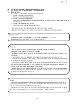
Notes : for engineers undertaking piping or electrical installation work
When a test run is completed, please make sure again that the electrical component box cover and the main body panel have been attached before you turn
the unit over to the customer.
(1) Test run from an outdoor unit.
Whether external inputs are set to ON or OFF, you can start a test run by using the SW5-1 and SW5-2 switches provided on the outdoor unit board.
Please set SW5-2 to ON for a cooling test run (It is set to OFF at the factory for shipment)
Turning SW5-1 from OFF to ON next will cause all connected indoor units to start.
When a test run is completed, please set SW5-1 to OFF.
Note: During a test run, an indoor unit cannot be operated from the remote control unit (to change settings). (“Under centralized control” is indicated)
8-4. Test operation
8-5. TRANSFER
○
Use the instruction manual that came with the outdoor unit to explain the operation method to the customer.
Please ask the customer to keep this installation manual together with the operation manual of his indoor units.
○
Instruct the customer that the power should not be turned off even if the unit is not to be used for a long time. This will enable operation of the air conditioner any time.
(Since the compressor bottom is warmed by the crank case heater, seasonal compressor trouble can be prevented.)
▲
▼
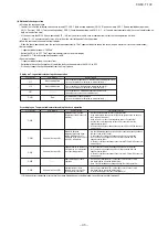
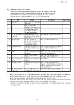
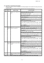
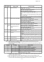
(4) After the refrigerant quantity check operation
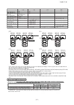
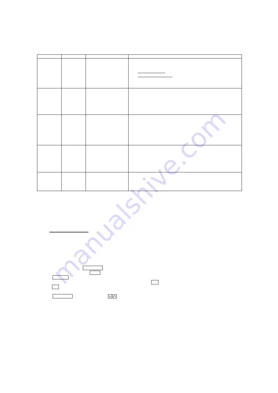
Following codes may be displayed at the end of check operation, other than “Co End”.
Check and take action according to the contents of remedy. And then, repeat the check operation.
Display on 7-segment indicator after the check operation (Displayed on master unit only in case of combination.)
Code indicator
Data indicator
Meaning
Remedy
Co
Hi
Refrigerant quantity over
①
Too much refrigerant is charged. Reduce the quantity.
< Guidelines of reduction >
・
Single machine:10 kg
・
Combination machine:20 kg
Make sure to recover the refrigerant from the check joint of liquid pipe operation valve
using the refrigerant recovery device.
Co
Lo
Low refrigerant quantity
①
Refrigerant quantity is insufficient. Recharge the refrigerant.
< Guideline of recharge>
・
20% of the additional refrigerant quantity for piping* (Upper limit: 5 kg)
Recharge the refrigerant in the liquid state from the check joint of low pressure line.
Make sure to measure the quantity before recharging.
Co
H_L
Couldn’t judge.
It cannot judge (a state that it cannot judge properly).
State of refrigerant might have been unstable during the check operation due to
influence of wind, temperature change, etc.
①
Check the expansion valve of indoor unit (disconnected coil, disconnected connector
or faulty expansion valve).
②
Implement at a later date by changing the conditions.
Co
---
Judgment was interrupted.
Check the following points.
①
Haven’t you changed the setting of dip switches after the start? Return them to
original setting.
②
Is any error code (E??) displayed? If Yes, refer to the troubleshooting section in the
technical data.
Co
HE
Starting conditions are not met.
Starting conditions are not met so that it cannot start the check operation.
Refer to “(2) Confirmation before implementing the refrigerant quantity check”.
※
“Additional refrigerant quantity for piping” means the value of “Additional refrigerant quantity for piping (P)” in the Section 4-4 Additional
refrigerant charge.
Other errors than above may also be displayed if errors are detected. In such occasion, inspect by referring to the separate technical data.
Summary of Contents for FDCH1010CKXE6G
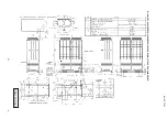
Page 8: ... 09 KX T 139 2 2 Exterior dimensions Models FDCH335CKXE6G K 400CKXE6G 450CKXE6G PCB003Z141 ...
Page 9: ... 09 KX T 139 Models FDCH504CKXE6G 560CKXE6G 560CKXE6G K 615CKXE6G 680CKXE6G PCB003Z142 ...
Page 10: ... 09 KX T 139 2 3 Electrical wiring Models All model PCB003Z139 ...
Page 41: ......
Page 42: ... 40 09 KX T 139 ...
Page 63: ... 09 KX T 139 Combination use PCB003Z587 61 ...
Page 64: ... 09 KX T 139 2 2 Exterior dimensions Models FDCH335CKXE6G K 400CKXE6G 450CKXE6G PCB003Z589 62 ...
Page 65: ... 09 KX T 139 Models FDCH504CKXE6G 560CKXE6G 560CKXE6G K 615CKXE6G 680CKXE6G PCB003Z590 63 ...
Page 66: ... 09 KX T 139 2 3 Electrical wiring Models All model PCB003Z588 64 ...

