background image

-

 6 

-

'09•KX-T-139

5

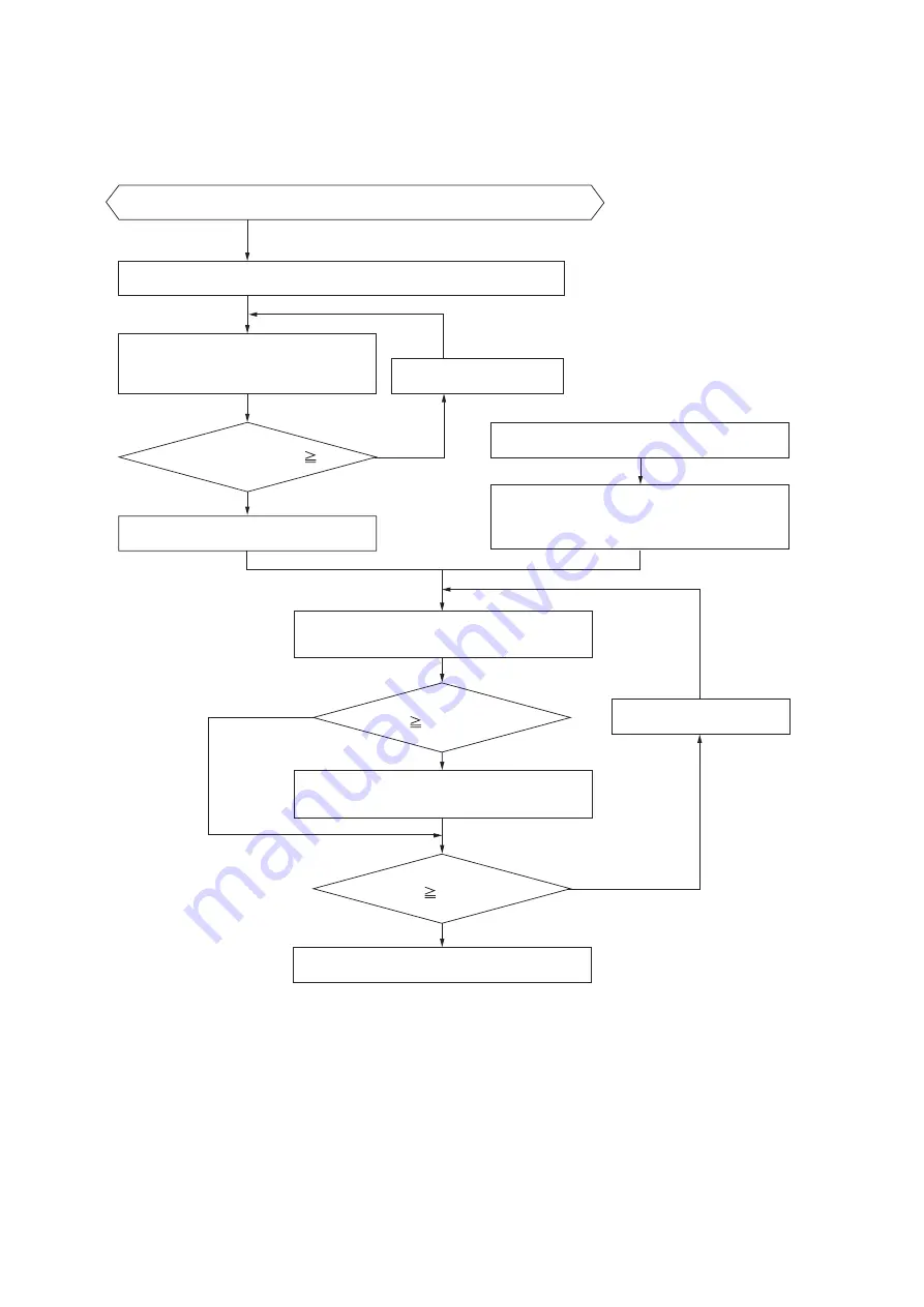
    SELECTION CHART

(1)  Equipment selection flow

Indoor unit 

capacity (tentative)   

Indoor Load

Total indoor unit 

capacity    System Capacity

YES

YES

YES

NO

NO

NO

Select an indoor unit that matches the indoor load (tentative).

Calculate the total indoor unit capacity.

Indoor unit 

capacity    Indoor Load

Equipment selection complete.

Change the outdoor unit.

Calculate the temperature compensation, 

then calculate the indoor unit capacity. 

(See item (2) (a) for the calculation method.)

Calculate temperature compensation and piping 

compensation, etc., then calculate the outdoor unit 

capacity. (See item (2) (b) for the calculation method.)

Select the outdoor unit (tentative).

Calculate the system capacity 

(See item (2) (c) for the calculation method.)

Calculate the indoor unit capacity. 

(See item (2) (d) for the calculation method.)

Calculate the load for each room separately, then determine the indoor load.

Change the indoor unit.

Summary of Contents for FDCH1010CKXE6G

Page 1: ...igh Head Models 100m cooling only OUTDOOR UNIT In this Technical Manual the High Head Models of outdoor units only are shown Regarding the standard models please see the Manual No 09 KX DB 127 Data Book and Manual No 09 KX SM 128 Service Manual updated July 08 2014 Service code blank D blank D Transfer production place from Japan to Thailand Except Specifications Exterior dimentions and Electrical...

Page 2: ...r units combination table 3 2 OUTDOOR UNIT 4 2 1 Specifications 4 2 2 Exterior dimensions 6 2 3 Electrical wiring 8 2 4 Noise level 9 3 PIPING SYSTEM 10 4 RANGE OF USAGE LIMITATIONS 11 5 SELECTION CHART 16 6 KX SERIES INSTALLATION MANUAL 28 7 CHECK OPERATION PROCEDURE 52 8 OUTDOOR UNIT Service code D 60 8 1 Specifications 60 8 2 Exterior dimentions 62 8 3 Electrical wiring 64 ...

Page 3: ...west height position has been increased from 50m to 100m 1 When the outdoor unit is located at higher position than the indoor unit Note 1 In case of less than 50m the standard models are applied 3 Connectable indoor capacity a Capacity from 50 to 200 is possible Note 2 When connecting the indoor unit type FDK FDFL FDFU or FDFW Series limit the connectable capacity not higher than 130 b Capacity f...

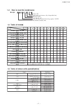
Page 4: ...sure type FDUM FDCH335CKXE6G K FDCH400CKXE6G 560CKXE6G FDCH560CKXE6G K FDCH615CKXE6G 1360CKXE6G Outdoor units to be combined FDC 1 3 Table of models 1 4 Table of indoor units panel Option Model Parts Model T PSA 36W E FDT Capacity 28 36 45 56 7 90 2 40 60 Capacity 22 28 36 Capacity 22 28 36 Capacity 28 45 56 Capacity 7 90 Capacity 2 40 Capacity 45 Capacity 7 TW PSA 24W E TW PSA 34W E TW PSA 44W E ...

Page 5: ...ectable capacity Number of connectable units Combination outdoor unit models Indoor unit Outdoor unit For two units for FDCH 735CKXE6G 1360CKXE6G Branch pipe set DOS 2A 1 Total capacity downstream Less than 180 180 or more but less than 371 371 or more but less than 540 540 or more Branching pipe set DIS 22 1 DIS 180 1 DIS 371 1 DIS 540 2 Total capacity downstream Less than 180 180 or more but les...

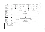
Page 6: ... 09 KX T 139 2 OUTDOOR UNIT 2 1 Specifications Single use Used also for combination Power factor 94㧛94 93㧛93 93㧛93 93㧛93 93㧛93 93㧛93 94㧛94 94㧛94 External static pressure Pa Max 50 PCB003Z138 a ...

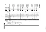
Page 7: ... 09 KX T 139 Power factor 93㧛93 93㧛93 93㧛93 93㧛93 93㧛93 93㧛93 Power factor 93㧛93 93㧛93 93㧛93 94㧛94 94㧛94 94㧛94 Combination use PCB003Z138 a ...

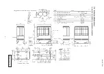
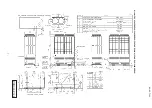
Page 8: ... 09 KX T 139 2 2 Exterior dimensions Models FDCH335CKXE6G K 400CKXE6G 450CKXE6G PCB003Z141 ...

Page 9: ... 09 KX T 139 Models FDCH504CKXE6G 560CKXE6G 560CKXE6G K 615CKXE6G 680CKXE6G PCB003Z142 ...

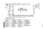
Page 10: ... 09 KX T 139 2 3 Electrical wiring Models All model PCB003Z139 ...

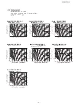
Page 11: ...ud Pressure Level standard 2 x 10 5 pa Mid Octave Band Frequency Hz N40 N50 N30 N60 N70 N80 63 125 250 500 1000 2000 4000 8000 30 40 50 60 70 80 30 40 50 60 70 80 Model FDCH504CKXE6G Noise level 61 5 dB A Souud Pressure Level standard 2 x 10 5 pa Mid Octave Band Frequency Hz N40 N50 N30 N60 N70 N80 63 125 250 500 1000 2000 4000 8000 30 40 50 60 70 80 30 40 50 60 70 80 Model FDCH450CKXE6G Noise lev...

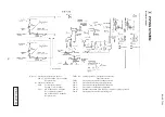
Page 12: ...pressor control ON 0 134MPa OFF 0 18MPa For protection ThI R1 R2 Cooling operation Frost prevention control Super heat control ThI R3 For super heat control of cooling operation Tho D For control of discharge pipe temperature Tho C For control of temperarure under the dome Tho S For control of suction pipe temperature Tho SC Electronic expansion valve EEVSC control of cooling operation Tho H For s...

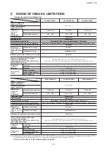
Page 13: ...re 23 or less relative humidity 80 or less Within 3 of rated voltage Within 15 of rated voltage Note 1 When connecting the indoor unit type FDK FDFL FDFU or FDFW not yet Series limit the connectable capacity not higher than 130 2 When the pipe extension length exceeds 510 m additional refrigerant oil must be charged 1 000 cc 3 In case of less than 50m the standard models are applied Indoor unit Ou...

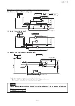
Page 14: ...Indoor unit Outdoor unit Indoor unit Outdoor unit First branch 50 100m 3 50 100m 3 MAX 90m 2 MAX 40m 2 MAX 90m MAX 90m 2 MAX 18m MAX 130m MAX 130m MAX 18m MAX 18m MAX 40m 2 MAX 18m MAX 18m MAX 18m Lowest indoor unit Highest indoor unit Highest indoor unit Lowest indoor unit First branch Header denotes 6 min or more 3 minutes or more from start to stop or 3 minutes or more from stop to start 3 min ...

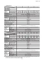
Page 15: ...Within 10 of rated voltage Within 15 of rated voltage Within 3 of rated voltage MAX 0 4m MAX 5m MAX 10m Combination use Indoor unit Outdoor unit Oil equalization piping MAX 90m 2 MAX 40m 2 MAX 130m MAX 5m Outdoor unit 1 Highest indoor unit denotes System FDCH1065 CKXE6G FDCH1130 CKXE6G FDCH1300 CKXE6G FDCH1360 CKXE6G Refer to page15 2 to 66 units 3 to 76 units 3 to 80 units 2 to 69 1 units 2 to 59...

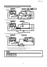
Page 16: ...essor stop start frequency Power source voltage Voltage drop during start Within 10 of rated voltage Within 15 of rated voltage Within 3 of rated voltage Allowable length of refrigerant piping height difference between indoor and outdoor unit 1 Branch pipe System Branch piping used 2 Header System Header used Note 1 A branch piping system cannot be connected after a header system 2 90m or less How...

Page 17: ... 15 09 KX T 139 14 16 18 20 22 43 40 35 30 25 20 0 5 26 24 Indoor air temperature C W B Applicable range Outdoor air temperature C D B Cooling operation Operating temperature range ...

Page 18: ...oor unit Calculate the temperature compensation then calculate the indoor unit capacity See item 2 a for the calculation method Calculate temperature compensation and piping compensation etc then calculate the outdoor unit capacity See item 2 b for the calculation method Select the outdoor unit tentative Calculate the system capacity See item 2 c for the calculation method Calculate the indoor uni...

Page 19: ...e item 3 a concerning the capacity compensation coefficient according to temperature conditions See item 3 b concerning the capacity compensation coefficient according to piping length See item 3 c concerning the capacity compensation coefficient according to indoor unit connected capacity This compensation should be carried out only in cases where the indoor unit total capacity is 100 or higher c...

Page 20: ...53 0 kW Outdoor unit maximum cooling capacity Item 2 b calculation Outdoor unit rated cooling capacity 45 0 kW Capacity compensation coefficient according to temperature conditions 0 95 Calculated according to Indoor 18 C WB Outdoor 35 C DB See page 19 Outdoor unit cooling capacity 45 0 kW 0 95 42 8 kW Capacity compensation coefficient according to piping length 0 95 calculated according to 100 m ...

Page 21: ...temperature 17 CWB Indoor air W B temperature 18 CWB Indoor air W B temperature 19 CWB Indoor air W B temperature 20 CWB Indoor air W B temperature 21 CWB Indoor air W B temperature 22 CWB Indoor air W B temperature 24 CWB Indoor air W B temperature 26 CWB Power consumption compensation coefficient 0 2 4 6 8 10 12 14 16 18 20 22 24 26 28 30 32 34 36 38 40 42 0 50 Outdoor air D B temperature CDB 0 ...

Page 22: ...f capacity in relation to one way length of refrigerant piping Note This table is for reference only If the refrigerant piping one way equivalent after the first branch is extended longer than 40 m it could drop further by about 10 in the worst case Gas pipe 25 4 Gas pipe 28 58 0 0 80 0 85 0 90 0 95 1 00 20 40 60 80 100 120 140 160 180 Capacity compensation coefficient Refrigerant piping one way e...

Page 23: ...gth m Gas pipe 31 8 Gas pipe 34 92 Gas pipe 38 1 Model FDCH850CKXE6G FDCH400CKXE6G FDCH450CKXE6G Model FDCH1065CKXE6G FDCH504CKXE6G FDCH560CKXE6G Gas pipe 38 1 0 80 0 85 0 90 0 95 1 00 Gas pipe 34 92 0 20 40 60 80 100 120 140 160 180 Capacity compensation coefficient Refrigerant piping one way equivalent length m Model FDCH1130CKXE6G FDCH560CKXE6G FDCH560CKXE6G Gas pipe 38 1 0 80 0 85 0 90 0 95 1 ...

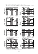
Page 24: ...ne part Capacity compensation coefficient Total capacity of concurrently operating indoor unit Capacity compensation coefficient Total capacity of concurrently operating indoor unit Cooling Capacity compensation coefficient Heating c The capacity compensation coefficient and power consumption compensation coefficient vary according to the total capacity of concurrently operating indoor units as sh...

Page 25: ...perating indoor unit Power consumption compensation coefficient Capacity compensation coefficient Power consumption compensation coefficient Model FDCH504CKXE6G 0 20 40 60 80 100 120 0 0 2 0 4 0 6 0 8 1 0 1 2 Capacity compensation coefficient Total capacity of concurrently operating indoor unit 0 20 40 60 80 100 120 0 0 2 0 4 0 6 0 8 1 0 1 2 Total capacity of concurrently operating indoor unit Pow...

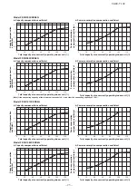
Page 26: ... consumption compensation coefficient Model FDCH735CKXE6G 0 20 40 60 80 100 120 0 0 2 0 4 0 6 0 8 1 0 1 2 Capacity compensation coefficient Total capacity of concurrently operating indoor unit 0 20 40 60 80 100 120 0 0 2 0 4 0 6 0 8 1 0 1 2 Total capacity of concurrently operating indoor unit Power consumption compensation coefficient Capacity compensation coefficient Power consumption compensatio...

Page 27: ...consumption compensation coefficient Model FDCH960CKXE6G 0 20 40 60 80 100 120 0 0 2 0 4 0 6 0 8 1 0 1 2 Capacity compensation coefficient Total capacity of concurrently operating indoor unit 0 20 40 60 80 100 120 0 0 2 0 4 0 6 0 8 1 0 1 2 Total capacity of concurrently operating indoor unit Power consumption compensation coefficient Capacity compensation coefficient Power consumption compensation...

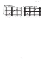
Page 28: ...oefficient Capacity compensation coefficient Power consumption compensation coefficient Model FDCH1180CKXE6G 0 20 40 60 80 100 120 0 0 2 0 4 0 6 0 8 1 0 1 2 Capacity compensation coefficient Total capacity of concurrently operating indoor unit 0 20 40 60 80 100 120 0 0 2 0 4 0 6 0 8 1 0 1 2 Total capacity of concurrently operating indoor unit Power consumption compensation coefficient Capacity com...

Page 29: ...nt Total capacity of concurrently operating indoor unit 0 20 40 60 80 100 120 0 0 2 0 4 0 6 0 8 1 0 1 2 Total capacity of concurrently operating indoor unit Power consumption compensation coefficient Capacity compensation coefficient Power consumption compensation coefficient Model FDCH1360CKXE6G ...

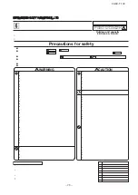
Page 30: ... 28 09 KX T 139 MITSUBISHI HEAVY INDUSTRIES LTD Precautions for safety PSB012D942H Outdoor unit capacity FDCH400 1360C WARNING CAUTION ℓ ...

Page 31: ...oor unit Optional parts Refrigerant distribution piping components supplied as optional parts will become necessary in installing the unit As refrigerant distribution piping components branching pipe sets model type DOS for the outdoor unit side piping branching pipe sets model type DIS and header sets model type HEAD for the outdoor unit side piping are available Select according to the applicati...

Page 32: ...ow will not accumulate 〇 A place where no TV set or radio receiver is placed within 5m If electrical interference is caused seek a place less likely to cause the problem 2 1 Selecting the installation location Please secure sufficient clearance room for maintenance work passage draft and piping If your installation site does not fulfill the installation condition requirements set out on this drawi...

Page 33: ...er and slave units with an oil equalization pipe when they are used in a combined installation It is not required when a unit is used as a standalone installation 4 1 Restrictions on the use of pipes Please use pipes clean on both the inside and outside and free from contaminants harmful to operation such as sulfur oxides dust chips oil fat and water Use the following material for refrigerant pipi...

Page 34: ...0 φ15 88 t 1 0 φ19 05 t 1 0 1 φ25 4 t 1 0 φ28 58 φ28 58 t 1 0 φ31 8 t 1 1 φ34 92 t 1 2 φ38 1 t 1 35 φ34 92 t 1 2 Total capacity of indoor units Less than 70 70 or more but less than 180 180 or more but less than 371 371 or more but less than 540 540 or more but less than 700 700 or more but less than 1100 1100 or more Liquid pipe φ 9 52 t 0 8 φ12 7 t 0 8 φ15 88 t 1 0 φ19 05 t 1 0 d Indoor unit sid...

Page 35: ... a 504 or a larger capacity unit should be arranged in the same manner as long as pipe connection points and directions are concerned except that the height of a unit is different Measurements in indicate those of a 504 or larger capacity unit 4 2 Pipe connection position and pipe direction Over 1 5m Pipe fastening position Total capacity downstream Less than 180 180 or more but less than 371 371 ...

Page 36: ...erform flushing To flush the piping charge nitrogen gas at about 0 02MPa with a pipe end closed with a hand When pressure inside builds up to a sufficient level remove the hand to flush in flushing a pipe close the other end of the pipe with a plug Operation procedure In laying pipes on the installation site keep the operation valves shut all the time Blazing must be performed under a nitrogen gas...

Page 37: ...st liquid to welded parts and flare joints and repair it After repair conduct an air tightness test again Always pull air from the pipes after the airtightness test 2 Vacuuming Please pull air from the check joints of the operation valves on both liquid and gas sides Please also pull air from the oil equalizing pipe Please pull air separately from the rest of the piping by using the oil equalizing...

Page 38: ...gether so that no gaps may be left between them and wrap them together with a connecting cable by a dressing tape d Although this air conditioning unit has been tested under the JIS condensation test conditions the dripping of water may occur when it is operated in a high humidity atmosphere 23 or a higher dew point temperature In such a case apply an additional heat insulation material of 10 to 2...

Page 39: ... it could cause explosion or ignition f The installation of an impulse withstanding type earth leakage breaker is necessary A failure to install an earth leakage breaker can result in an accident such as an electric shock or a fire Do not turn on the power until the electrical work is completed Be sure to turn off the power when servicing g Please do not use a condensive capacitor for power factor...

Page 40: ... 38 09 KX T 139 terminal on the terminal block is specified to connect only an optional auxiliary heater power supply for heater φ ...

Page 41: ......

Page 42: ... 40 09 KX T 139 ...

Page 43: ...in a combined installation set the Outdoor Unit No switch to the same number with a master unit and then set the dipswitch SW4 7 of the slave unit to ON Set both master and slave units to the same outdoor unit number Turn on power in order from the outdoor unit to indoor units Give a one minute or longer interval for them When there are some units not supporting new SL connected in the network set...

Page 44: ... switch back to the Number of Connected Indoor Units Input screen Input the number of connected indoor units from the 7 segment display panel of each outdoor unit master unit in case of combination Please input the number of connected indoor units on the same refrigerant line in case of combination for each outdoor unit You can input it from P33 on the 7 segment display panel When the number of co...

Page 45: ...urce Outdoor unit power source Indoor unit indoor outdoor No SW Outdoor unit outdoor No SW Network connectors Start automatic address setting Set starting address Set the number of indoor unit Polarity setting 7 segment display Indoor No SW 000 000 Outdoor No SW 49 49 Indoor unit address setting Outdoor unit address setting Outdoor No SW 49 00 31 Address Change is used when you want to change an i...

Page 46: ...eing transmitted SET COMPLETE will be indicated Then the remote controller display will change to the normal state If you want to end the session without reflecting new address settings Before you complete the present address setting session press the ON OFF switch Then the display is change to exit from this mode and switch the display to the normal state All address settings changed in the sessi...

Page 47: ...04 Contents of a display Please check Contents of a display Cause Code E2 E3 E11 E12 E31 E46 Duplicating indoor unit address Incorrect pairing of indoor outdoor units Incorrect adderess setting of indoor units Address setting for plural remote controllers Incorrect setting Duplicating outdoor unit address Incorrect manual address setting Indoor unit address is set from plural remote controllers Pl...

Page 48: ...ecifications SW setting on PCB SW5 5 SW6 3 to ON C P on 7 segment SW3 2 to ON SW5 1 to ON SW5 2 to ON Cooling test run Communication method selection ON Previous SL communication OFF New SL communication J13 Short circuited Factory default J13 Open External input selection CnS1 CnS2 only Short circuited Level input Open Pulse input High static pressure mode J15 Short circuited Factory default J15 ...

Page 49: ...sing unit of the same refrigerant line CAUTION Please make sure that the operation valves gas liquid oil equalizing pipe for a combined installation only are full open before a test run Conducing a test run with any of them in a closed position can result in a compressor failure 8 TEST OPERATION AND TRANSFER 8 1 Before starting operation 8 2 Check operation Important Check operation allows proving...

Page 50: ...ted without play Is the power supply to the indoor unit turned on When any error is detected errors other than those listed above may be displayed In such occasion refer to page 56 Abnormal indoor unit No Abnormal indoor unit No Abnormal indoor unit No Display on 7 segent indicator during check operation a Starting the check operation Confirm that all of the following switches are turned OFF SW3 2...

Page 51: ...wing switches are turned OFF SW3 2 Auto backup operation SW3 6 Pipe wash mode SW3 7 Forced cooling heating mode SW5 1 Test run SW5 2 Test run cooling setting SW5 3 Pump down operation and SW5 6 7 8 Capacity measurement mode In case of combination on both master slave units At the next turn the SW3 4 Refrigerant quantity check operation OFF ON only on master unit in case of combination so that the ...

Page 52: ...r bottom is warmed by the crank case heater seasonal compressor trouble can be prevented 4 After the refrigerant quantity check operation Following codes may be displayed at the end of check operation other than Co End Check and take action according to the contents of remedy And then repeat the check operation Display on 7 segment indicator after the check operation Displayed on master unit only ...

Page 53: ...on Procedures For the meanings of failure diagnosis messages please refer to the nameplate provided on the unit on the back of the controller lid 5 7 segment LED indication Data are indicated when so chosen with the indication selector switch For the details of indication please refer to the cable name plate attached on the unit On the face of the controller lid 6 Internal wiring After maintenance...

Page 54: ...played on the 7 segment display of master outdoor unit If the unit has been operating before check operation wait for 5 minutes after stopping the unit operation before starting check operation in order to avoid misjudgment In combination use judging operation valves opened or closed by check operation can be done as no good NG when all of operation valves in liquid line gas line and oil equalizin...

Page 55: ... method refer to 3 Confirmation before check operation 2 For details of check operation refer to 4 Check operation procedure 3 For measures to be taken in case of NG refer to 5 Measures to be taken after check operation Preliminary check Note 1 Judgment of checked result Note 3 End NG OK Auto checking Note 2 Start ...

Page 56: ...thod is of new SL Check the model name of outdoor unit indoor units central control device etc System is not in error stop condition Check to see if any error code E is displayed on indoor or outdoor unit 6 Outdoor unit operation valve Outdoor unit operation valve is opened 1 Check visually 7 Refrigerant amount Proper amount of refrigerant is charged Check the additional charged amount of refriger...

Page 57: ...s judged normal End the check operation CHL Operation valve may be closed Refer to 5 Measures to be taken after check operation CHU Anomalous indoor unit No Refrigerant piping or signal wiring between indoor and outdoor units may not be connected correctly CHJ Anomalous indoor unit No Indoor expansion valve may not be operating properly CHE Check operation has not ended properly All judgment resul...

Page 58: ...r may be anomalous or disconnected 2 See page 58 Operation valve on outdoor unit may be left closed Check it especially when many indoor units No are displayed in data display column of CHU it may be displayed by influence of liquid flooding due to the trouble on any other indoor unit If CHJ is displayed at the same time check preferentially the indoor unit displaying CHJ and after repairing perfo...

Page 59: ...n place Refer to the technical manual or the above It might have been started operation while bottom of compressor was still cold Perform check operation again after the bottom of compressor has been enough warm E 49 Low pressure anomaly Refrigerant circuit may be choked at a certain place Refer to the technical manual or the above E 36 3 Liquid flooding anomaly It may be in the same condition as ...

Page 60: ...unit 3 Indoor unit 4 2 If the connector comes off by a weak pull it s no good If not come off It s OK The connector of indoor heat exchanger temperature thermistor Normal Disconnected 3 If the connector comes off by a weak pull it s no good If not come off It s OK The connector of indoor expansion valve coil Normal Disconnected 4 The indoor expansion valve coil itself Normal Disconnected from main...

Page 61: ...57 FD 18 FD 58 FD 19 FD 59 FD 20 FD 60 FD 21 FD 61 FD 22 FD 62 FD 23 FD 63 FD 24 FD 64 FD 25 FD 65 FD 26 FD 66 FD 27 FD 67 FD 28 FD 68 FD 29 FD 69 FD 30 FD 70 FD 31 FD 71 FD 32 FD 72 FD 33 FD 73 FD 34 FD 74 FD 35 FD 75 FD 36 FD 76 FD 37 FD 77 FD 38 FD 78 FD 39 FD 79 FD 40 FD 80 FD Date of installation d m y Name of installer Superlink version Superlink II Superlink I In case of Superlink I the che...

Page 62: ... 09 KX T 139 OUTDOOR UNIT 2 1 Specifications Single use Used also for combination PCB003Z587 60 ...

Page 63: ... 09 KX T 139 Combination use PCB003Z587 61 ...

Page 64: ... 09 KX T 139 2 2 Exterior dimensions Models FDCH335CKXE6G K 400CKXE6G 450CKXE6G PCB003Z589 62 ...

Page 65: ... 09 KX T 139 Models FDCH504CKXE6G 560CKXE6G 560CKXE6G K 615CKXE6G 680CKXE6G PCB003Z590 63 ...

Page 66: ... 09 KX T 139 2 3 Electrical wiring Models All model PCB003Z588 64 ...

Page 67: ...rigeration Systems Headquarters 16 5 2 chome Kounan Minato ku Tokyo 108 8215 Japan Fax 03 6716 5926 Because of our policy of continuous improvement we reserve the right to make changes in all specifications without notice Copyright MITSUBISHI HEAVY INDUSTRIES LTD c ...

Reviews: