-
185
-
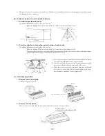
1.5.1 Installation of indoor unit
(1)
Ceiling recessed compact type (FDTC)
(a) Selection of installation location
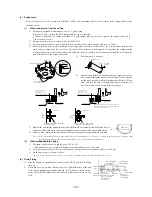
1) Select location where the space above ceiling is larger than those mentioned below and perfect draining can be assured.
2) With the customer’s consent, select a location with following suitable conditions.
a) Where cool air or hot air can easily pass through.
If the height of the location exceeds 3 m, hot air will gather in the ceiling. Suggest to the customer to also install a circula-
tor.
b) Where water can be completely drained. A sloping location for drainage.
c) Where there are no wind disturbances to the suction inlet and blowing outlet, where the fi re alarm will not be set off er-
roneosly, where no short circuits occur.
d) Where there is no direct sunlight.
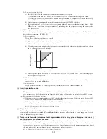
e) Please with the environmental dew-point temperature is lower than 28ºC and the relative humidity is less than 80%.
This unit is tested under ISO installation conditions to make sure that there are no defects. However, if it is
operated under conditions of high humidity that exceed the conditions above, there is danger of condensate
falling from the unit. If there is a possibility that the unit will be used under such conditions, dress 10~20 mm
of insulation on the entire unit body, the piping and drain pipe.
3) Consider the supporting strength of the location. If the strength is not suffi cient to sustain the unit weight, use reinforcing
materials.
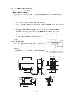
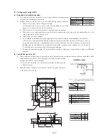
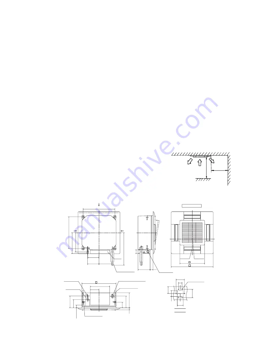
(b) Installation space for unit
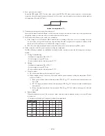
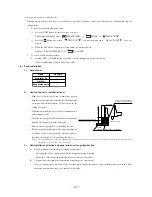
a) When
a
suffi cient interval cannot be secured between the unit and a wall or
another unit, shut up diffusers on that side to block winds and make sure that
no short-circuiting is occurring. (A wind blocking material is available as an
optional part)
• Do not use the unit in the “Lo” wind mode, when winds are blown into two
or three directions.
1000 or more
Unit: mm
Obstacle
1000 or more
• Installtation space
(
)
A
A
A
144
323
137
197
35
93
196
248
185
190
223
321
348
530 Suspension bolts pitch
45 or more
530 Suspension bolts pitch
541
64
200
48
Lug for
suspension bolts
Control
box
Drain hose piece
Gas piping
Liquid piping
Suspension bolts
Drain
φ
6.35 (1/4")
φ
12.7 (1/2")
(Accessory)
(Installed at site)
(Connectable with VP25)
(M10 or M8)
Air supply
Air return
grille
Decorative Panel
Opening for
exit wiring
VIEW A
60
140
100
100
115
140
6-
φ
4
Holes for
tapping screws
Hole
413
700
570
Unit: mm
Note (1) If you are mounting units close together, leave
a space of 4000 or greater between unit.

