-
195
-
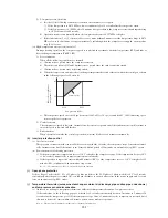
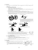
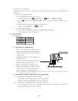
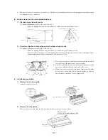
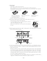
Drain plug
Air supply (small)
Striker
Drain piping
Air screen
Air supply (small)
Refrigerant
piping
Screw
1 2
4
1
2
3
3
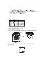
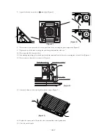
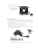
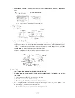
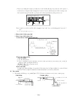
Louver
Louver motor
L
L
Connector
Louver motor
Connect the (white, 5p) louver motor con-
nector.
Place each of the connectors inside the con-
trol box.
Note (1) : If the air outlet louver does not operate using
the remote controller, check the connector’s
connection, then turn the main power supply
OFF for 10 seconds or longer and turn the
power ON again.
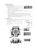
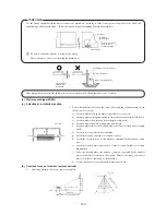
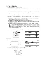
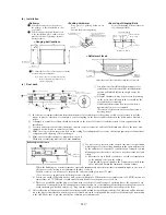
7) If the vertical air-fl ow direction is fi xed
• This decorator panel is designed so that you can fix the vertical air-flow direction at each air supply to match the environ-
ment at your installation location. Set it as required by the customer. Furthermore, when the vertical air-flow direction is
fixed, remote control operation and all automatic controls are disabled. The actual setting may also differ from the LCD
display in the remote controller.
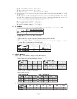
Turn off the main power supply (turn it off at the ground fault circuit breaker).
Disconnect the connector to the louver motor at the air supply you want to fix the position of.
Wrap vinyl electrical tape around the disconnected connector to insulate it.
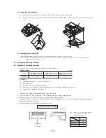
Slowly move the vertical air-flow louver you want to fix the position of by hand and set the vertical air-flow direction
so that it is within the range shown in the table below.
Note (1) : Do not set the position outside this range.
Doing so causes condensate to drip and to form as well as dirtying of the ceiling surface, and could cause abnormal operation.
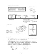
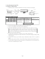
Vertical air-flow
direction criterion
L Dimension (mm)
Horizontal 30º
36.5
Downward 70º
22.5
* It can be set anywhere desires as long as it is within a range of 22.5 and 36.5 mm.
<Setting Range>

