-
204
-
2)
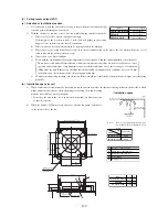
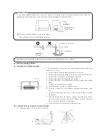
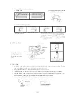
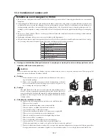
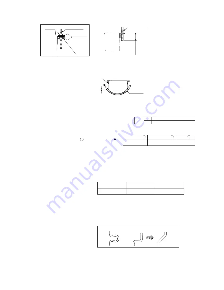
Adjusting the unit’s levelness
a)
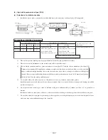
Adjust the out-levelness using a level vial or by the following method.
• Make adjustment so that the relation between the lower surface of the indoor unit proper and water level in the hose
becomes given below.
b)
Unless the levelness is adjusted properly, the malfunction of the fl oat switch will occur.
3)
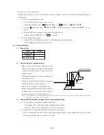
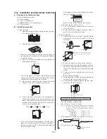
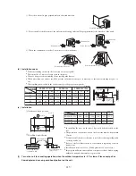
Blower fan tap switch
The following two methods are available in switching the blower fan
tap. Switch to the high-speed tap with one of these methods.
Set SW9-4 provided on the indoor unit PCB to ON.
By means of function setting from the remote con-
trol unit, set the setting
C
of “I/U FUNCTION ”
(indoor unit function) to “Hi CEILING 1 ” (high-speed
tap) as shown right.
For the details of operating procedures, please refer to the installation manual of your remote control unit.
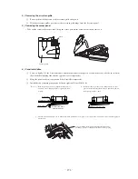
Suspension bolt
M10 Washer
M10 nuts
Indoor unit
M10 Spring washer
Suspension bolt M10
Indoor unit
60mm or less
PVC hose
Piping side
Supply water
0 ~ 5 mm
Bring the piping side slightly lower
SW9-4
ON
OFF
Fan control,high speed (High ceiling)
Fan control,standard
Function number
A
Function description
B
Setting
C
01
Hi CEILING SET
Hi CEILING 1
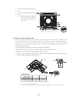
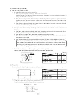
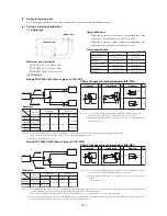
(iii) Duct
work
Supply air duct
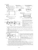
• 2-spot, 3-spot and 4-spot with ø200 type duct are the standard specifications. Determine the number of spots based on
following table.
Notes (1) Shield the central supply air port for 2-spot.
Notes
(2) Shield the supply air port around the center for 3-spot.
• Limit the difference in length between spots at less than 2:1.
• Reduce the length of duct as much as possible.
• Reduce the number of bends as much as possible. (Corner R should be as larger as possible.)
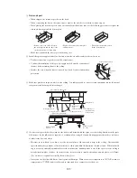
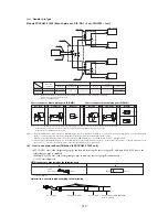
Access door
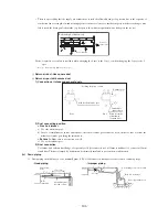
Access door must be provided without fail.
•
Dimensions of access door and service space
(See exterior dimensions in page 98 to 100.)
FDUMA252, 302R
FDUMA402 ~ 602R
FDUMA202R
2-spot
2 ~ 3-spot
(1)
3 ~ 4-spot
(2)
Bad example
Bad example
Good example

