-
217
-
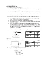
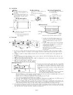
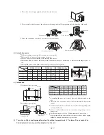
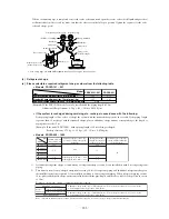
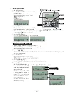
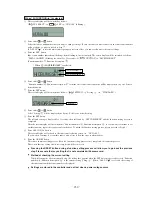
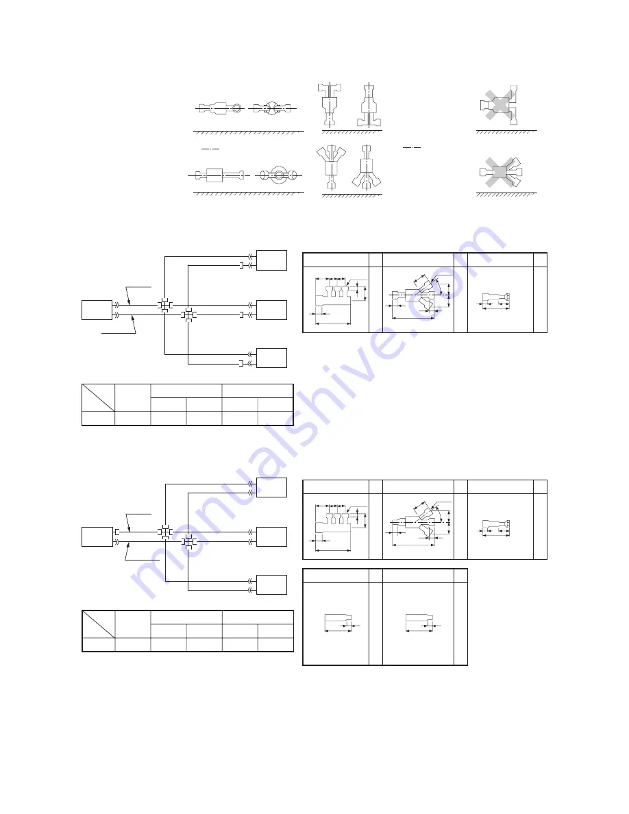
< 2-Way Branch >
< 3-Way Branch >
Floor
Floor
Floor
Floor
Floor
Floor
Mount
sections level with the floor.
Mount sections
perpendicular to the floor.
•
The branch piping (both gas and liquid lines) should always be arranged to have a level or perpendicular
branch.
(iii)
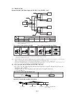
Triple
type
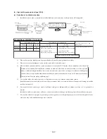
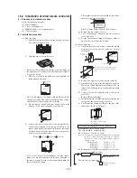
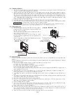
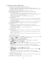
Model FDCVA602 [Branch pipe set : DIS-TA1]
Outdoor unit
Indoor unit
Chart of shapes of branch piping parts (DIS-TA1)
Gas pipe
Liquid pipe
Reducer
Mark
Mark
Mark
100
80 80
8
105
50
10
300
ID9.52
ID15.88
ID12.7
×
3
ID9.52
×
3
ID9.52
φ
6.35
Flared nut
100
10
14˚
100
8
237
8
30
30
Liquid line
Gas line
φ
9.52
×
t 0.8
φ
9.52
×
t 0.8
φ
15.88
×
t 1.0
φ
12.7
×
t 0.8
Item
Liquid pipe
Indoor unit
combinations
Main pipe
Branch pipe
Main pipe
Branch pipe
Gas pipe
Model
FDCVA602
20
+
20
+
20
Notes (1) Use the irregular fi ttings
3
supplied with the branch piping set on the indoor unit side, and make the branch piping
(branch ~ indoor unit) liquid piping size
φ
9.52.
Notes (1)
1
to
3
in the drawing include parts provided in the branch piping set. It shows
the codes for the shapes of different-diameter connections.
(2)
Branch piping should always be arranged to have level or perpendicular
branch.
(See the above fi gure.)
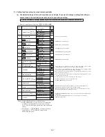
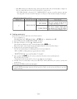
Model FDCVA802 [Branch pipe set : DIS-TB1]
Outdoor unit
Indoor unit
Chart of shapes of branch piping parts (DIS-TB1)
Gas pipe
Liquid pipe
Mark
Mark
100
80 80
10
300
ID9.52
ID25.4
ID15.88
×
3
ID9.52
×
3
10
0
10
14˚
100
8
8
217
8
30
30
Liquid line
Gas line
φ
25.4
×
t 1.0
φ
15.88
×
t 0.8
φ
9.52
×
t 0.8
φ
9.52
×
t 0.8
Item
Liquid pipe
Indoor unit
combinations
Main pipe
Branch pipe
Main pipe
Branch pipe
Gas pipe
Model
FDCVA802 30
+
30
+
30
Reducer
Mark
8
105
50
ID9.52
φ
6.35
Flared nut
-
Reducer
Mark
OD12.7
ID9.52
80
10
-
-
Reducer
Mark
OD15.88
ID12.7
80
10
Notes (1)
1
to
2
in the drawing include parts provided in the branch piping set. It shows
the codes for the shapes of different-diameter connections.
(2)
Branch piping should always be arranged to have level or perpendicular
branch.
(See the above fi gure.)
Notes (1) For model FDCVA802, always use ø12.7 mm liquid pipes, when the length of the main “L” exceeds 40 m. If ø9.52 mm pipes are used in an installation having over
40 m piping, they can cause performance degradation and/or water leaks from an indoor unit.
When the pipe length measures 60 m or longer for the model FDCVA802, we recommend the use of a ø12.7 mm liquid main.
(2) One-way pipe length should measure 5 m at a minimum. If the pipe length measures less than 5 m, then reduce the quantity of charged refrigerant. If you need to
recover or recharge refrigerant, contact our sales agent found in your neighborhood.

