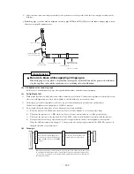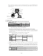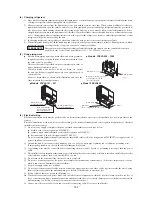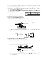
-
234
-
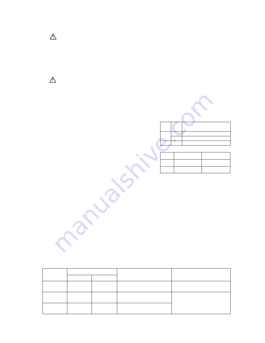
Models FDCVA302 ~ 1002
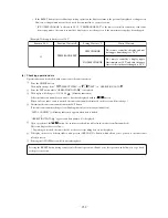
1) Test run method
a) A test run can be initiated from an outdoor unit by using SW3-3
(SW5-3) and SW3-4 (SW5-4) for on-site setting.
b) Switching SW3-3 (SW5-3) to ON will start the compressor.
c) The unit will start a cooling operation, when SW3-4 (SW5-4) is
OFF, or a heating operation, when SW3-4 (SW5-4) in ON.
d) Do not fail to switch SW3-3 (SW5-3) to OFF when a test run
is completed.
Note (1) Values in ( ) show in the case of the 302 model.
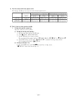
2) thecking the state of the unit in operation
Use check joints provided on the piping before and after the 4-way
valve installed inside the outdoor unit for checking discharge pres-
sure and suction pressure.
As indicated in the table shown on the right, pressure detected at
each point will vary depending on whether a cooling or heating
operation has been selected.
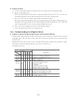
3) Setting SW3-1, SW3-2 on site or open J7 (SW7-1)
a) Defrost control switching [SW3-1]
When this switch is turned ON, the unit will run in the defrost mode more frequency.
Set this switch to ON, when installed in a region where outdoor temperature falls below zero during the season
the unit is run for a heating operation.
b) Snow guard fan control [SW3-2]
When this switch is turned on, the outdoor unit fan will run for 10 seconds in every 10 minutes, when outdoor
temperature falls to 3°C or lower and the compressor is not running.
When the unit is used in a very snowy country, set this switch to ON.
c) High pressure control [J7 (SW7-1)]
• When the option parts that change air fl ow from outlet are used, cut (open) J7.
Cut the jumper wire into two parts and ensure that they are kept isolated from each other.
SW3-3
(SW5-3)
Cooling
operation
Discharge pressure
(High pressure)
Discharge pressure
(High pressure)
Suction pressure
(Low pressure)
Suction pressure
(Low pressure)
Charge port of the
gas service valve
Check joint of the pipe
Heating
operation
SW3-4
(SW5-4)
ON
OFF
OFF
ON
–
Cooling during a test run
Heating during a test run
Normal or After the test operation
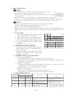
• Before conduct a test run, do not fail to make sure that the service valves are not closed.
• Turn on power 6 hours prior to a test run to energize the crank case heater.
• In case of the f irst operation after turning on power, even if the unit does not move for 30 minutes,
it is not a breakdown.
• Always give a 3-minute or longer interval before you start the unit again whenever it is stopped.
• Removing the service panel will expose high-voltage live parts and high-temperature parts, which are quite dangerous.
Take utmost care not to incur an electric shock or burns. Do not leave the unit with the service panel open.
• When you operate switches (SW3, SW5) for on-site setting, be careful not to touch a live part.
• You cannot check discharge pressure from the liquid service valve charge port.
• The 4-way valve (20S) is energized during a heating operation.
• When power supply is cut off to reset the unit, give 3 or more minutes before you turn on power again after power is cut off.
If this procedure is not observed in turning on power again, “ Communication error between outdoor and indoor unit ” may
occur.
}
A failure to observe
these instructions
can result in a com-
pressor breakdown.
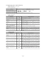
Error indicated
on the remote
control unit
RED LED
GREEN LED
Failure event
Action
Printed circuit board LED (They cycles of 5 seconds)
E39
E40
E49
1 time flash
1 time flash
1 time flash
Keeps flashing
Keeps flashing
Keeps flashing
63H1 actuation or operation with
service valve shut
(occurs mainly during a heating operation)
Open phase
Check power cables for loose contact
or disconnection
1.
2.
Check whether the service valves
are open.
If an error has been canceled when 3
minutes have elapsed since a compressor
stop, you can restart the unit by effecting
check result from the remote control unit.
Low pressure error or operation with
service valves shut
(occurs mainly during a cooling operation)
4) Failure diagnosis in a test run
CAUTION
WARNING


