-
263
-
LED1
JSW11
JSW10
JSW11
Match to the PCB conditions
that existed before replacement.
JSW10
Match to the PCB conditions
that existed before replacement.
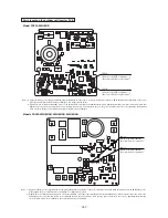
Notes (1) Apply the silicone grease supplied with the component uniformly to the surface of the power transistor on the new PCB, then mount it on the PCB. If the grease
is not applied, the power transistor may be damaged. Use all the silicone grease.
(2) Tighten the power transistor mounting screws of the inverter PCB, and connect the terminal block, faston terminals and connectors. After connection, make sure
tightening was not forgotten and parts were not partially inserted only. In particular, make sure the power transistor is not loose by tightening the mounting
screws securely. If they are not tightened, the power transistor may be damaged.
( )
( )
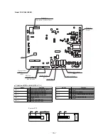
Parts layout on the outdoor unit inverter PCB
Model FDCVA302HENR
P1
N1
P3
N3
U
V
W
JSW10 JSW11
LED1
CNI2
CNE
CNCAN
CNO
CNI4
N2
N2
P2
P2
JSW10
Match to the PCB conditions
that existed before replacement.
JSW11
Notes (1) Apply the silicone grease supplied with the component uniformly to the surface of the power transistor on the new PCB, then mount it on the PCB. If the grease
is not applied, the power transistor may be damaged. Use all the silicone grease.
(2) Tighten the power transistor mounting screws of the inverter PCB, and connect the terminal block, faston terminals and connectors. After connection, make sure
tightening was not forgotten and parts were not partially inserted only. In particular, make sure the power transistor is not loose by tightening the mounting
screws securely. If they are not tightened, the power transistor may be damaged.
( )
Match to the PCB conditions
that existed before replacement.
( )
Models FDCVA402HENAR, 502HENAR, 602HENAR


