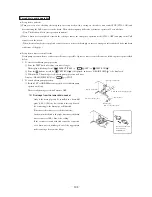
-
211
-
4)
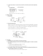
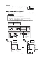
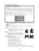
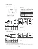
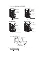
When constructing drain piping for several units, position the common pipe about 100 mm below the drain outlet of each unit
as shown in the sketch. Use VP-30 (11/4˝) or thicker pipe this purpose.
5)
Be sure to provide heat insulation to hard PVC pipes of indoor placement.
6)
Do not ever provide an air vent.
7)
Avoid postitioning the drain piping outlet at a place where generation of odor may be stimulated. Do not lead the drain piping
direct into a sewer from where sulfur gas may generate.
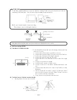
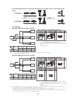
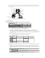
If the duct is connected and then the blower is operated,
inside air pressure will become negative compared with
the atmospheric pressure.
Duct
Duct
Air filter
Air outlet grille
In running
In stopping
Pressure head loss,
suction side 10 mmAq
Drain pipe
Drain pan
10 mm
Suction grill
Example: If the pressure loss at the suction side, such as the suc-
tion grill, air filter and duct, is 100 Pa, the level of drain
water will rise approx. 10 mm higher than the state of
operation stop.
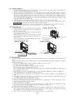
<Provision of trap>
Since the drain outlet is disposed at a position
that makes the pressure negative, it is necessary
to provide a trap (during the piping work) in order
to prevent water leakage due to rising of water
level in the drain pan.
Trap must be so constructed to facilitate cleaning.
It should be better to employ a “T” joint as shown
below. In addition, the height of trap should be
as specified below. The trap should be provided
close to the unit.
Unit
Drain connection
H
2
H
1
Provide a trap on way
of the drain pipe as
shown at left.
H
1
=100 mm or static pre-
ssure of blower
H
2
=1/2 H
1
or 50 ~ 100 mm
(d) Drain
Piping
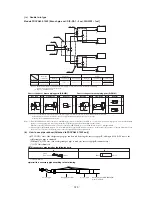
1)
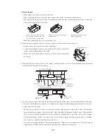
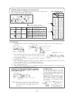
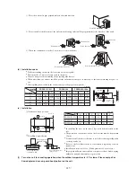
Drain piping should always be in a downhill grade (1/50~1/100) and avoid riding across an elevation or making traps.
Avoid riding across an elevation
Keep free from traps
Do not pipe under water
Air vent
Improper piping
Suspension
bolts
1.5m ~ 2m
Heat
insulation
A downhill grade
of 1/100 or more
Good piping
2)
When connecting the drain pipe to unit, pay sufficient attention not to apply
excess force to the piping on the unit side. Also, fix the piping at a point as
close as possible to the unit.
3)
For drain pipe, use hard PVC general purpose pipe VP-25(I.D.1˝) which can
be purchased locally.
A downhill grade of
1/100 or more
Secure the elevation as high as possible
(approx. 100 mm)
V.P.30
1020 m
3
/h
B
1020 m
3
/h
B
4080 m
3
/h
A
4080 m
3
/h
Supply
(blowout)
chamber
Air conditioner
indoor unit
With air filter
A
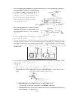
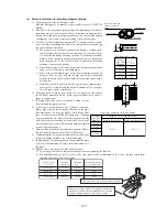
<Table of simplified selection
of duct dimensions>
Air
volume
Duct
(mm
×
mm)
4080m
3
/h
(68m
3
min)
250
×
830
1020m
3
/h
(17m
3
min)
250
×
270
Calculation of duct resistance
(Use following simplified calculations.)
Linear pipe
section
Calculate based on 1 Pa
per 1 m in length 1 Pa/m.
Curved pipe
section
Take a curved section as equivalent to 3
~4 m in straight line.
Blowout
section
Calculate based on 25 Pa.
Chamber
Calculate by taking 1 pc. as 50Pa.
Suction grill
(with filter)
Calculate by taking 1 pc. as 40Pa.
Square duct
Dimensions
Duct form
Item
Air
volume
m
3
/h(m
3
/min)
100
200
300
400
500
600(10)
800
1,000
1,200(20)
1,400
1,600
1,800(30)
2,000
2,400
3,000(50)
3,500
4,000
4,500
5,000
5,500
6,000(100)
(mm
×
mm)
250
×
60
250
×
90
250
×
120
250
×
140
250
×
170
250
×
190
250
×
230
250
×
270
250
×
310
250
×
350
250
×
390
250
×
430
250
×
470
250
×
560
250
×
650
250
×
740
250
×
830
250
×
920
250
×
1000
250
×
1090
250
×
1180
Section A
Section B
Section B
Section A
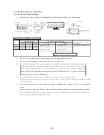
<Simplifi ed method for determination of duct dimensions>
In the following method, it is assumed that the friction resistance per unit length of duct is
1 Pa/m (0.1 mm Aq/m) and a side of duct is 250 mm.
Air volume rating is assumed to be FDUA1001R.
Summary of Contents for FDCVA1002HESAR
Page 107: ... 106 60 17 150 b Wireless remote controller Unit mm ...
Page 119: ... 118 Model FDCVA1002HESAR Polar white ...
Page 133: ......


