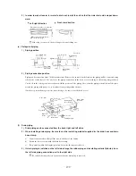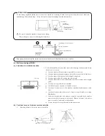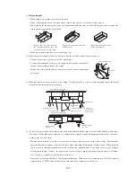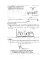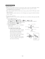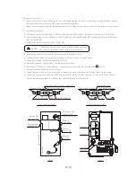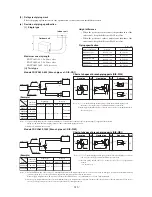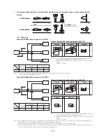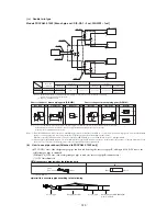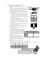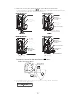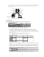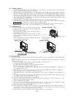
(e) Drain Test
When the drain piping work is over, inject water to inspect if the piping is
arranged properly or not.
○
Remove the side panel and supply gradually 1,000 cc of water to see if
water is drained smoothly or not. Check also for water leakage.
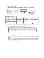
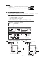
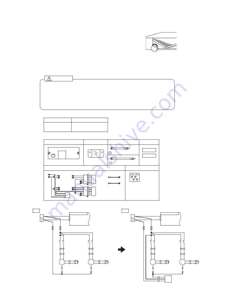
( f ) The fan controller kit for high static pressure duct. ( Optional )
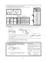
The way of installing the optional fan controller for high static pressure ducts. Install the controller in accordance
with the following procedure.
WARNING
① Consult your dealer for the installation of the controller.
② Only qualified electrician must install the controller.
③ Remove the control box before the installation.
Before installing the product, take it out from the package and place it on the floor.
④ Be sure to turn off the power supply during installation.
Unless the above precautions are observed, it could cause electrical shocks or fire.
Model
FDU801R,1001R
U‑FCR
Fan controller kit
5
4
3
1
2
6
8
7
F2(6.3A)
F1(6.3A)
52FL,3
52FH,3
F1
F2
52FH,4
52FL,4
52FL,5
52FH,5
<FC>
CNF
CFI1
52FH,6
52FL,6
CFI2
Fan controller
1 piece
Wiring
<FMI‑1>
CNF2
CNF3
<FMI‑2>
TB,N
TB,L
White
Red
a (L=92):5 pieces
Band
Tapping screw
※Screws removed
during modification
are reused.
F2
F1
4 pieces
Label
M
1〜
1〜
M
F1(6.3A)
F2(6.3A)
M
1〜
1〜
M
b (L=140):4 pieces
Bracket
1 piece
(M3:2 pcs.)
(M4:2 pcs.)
1 piece each
I2
FM
FM
I1
4
4
6
6
5
5
3
3
I1
CF
White
Red
52
FH
FL
52
FH
52
FL
CnF
3
I2
CnF
3
CnF
5
CnF
5
CF
H
L
CnF
5
CnF
3
Printed circuit board
CnF
2
CnF
4
CnF
4
CnF
2
CnF
4
CnF
2
Pink
Yellow/white
Black
52
Yellow
H
L
Orange/white
Orange
TB
1
2
I2
FM
FM
I1
4
4
6
6
5
5
3
3
I1
CF
52
FH
FL
52
FH
52
FL
CnF
3
I2
CnF
3
CnF
5
CnF
5
CF
H
L
CnF
5
CnF
3
CnF
CnF
2
CnF
4
CnF
4
CnF
2
CnF
4
CnF
2
52
H
L
FC
Blue
TB
1
N
2
N
Red
Red
Red
Red
Red
Red
Red
Red
Red
White
White
White
White
White
White
White
White
White
White
White
White
White
White
White
White
White
White
White
Pink
Pink
Pink
Black
Black
Black
Black
Black
Yellow
Orange
Yellow
Orange
Yellow
Orange
Yellow
Orange
White
Red
Red
White
White
Pink
Red
Red
Pink
Pink
Pink
White
White
White White
White
White
White
White
White
White
White
White
White White
White
White
White
White
White
Black
Black
Black
Black
Black
Black
Red
Red
Red
Black
Black
Black
Red
Red
Red
Yellow/white
Yellow
Orange/white
Orange
Yellow
Orange
Yellow
Orange
Yellow
Orange
Yellow
Orange
Red
Printed circuit board
1) Applicable models and corresponding fan controller kit
2) Component parts list
3) Electric circuit diagram (Change the sections indicated with bald lines.)
-
-
212
Old
New
F1(6.3A)
F2(6.3A)
Summary of Contents for FDCVA1002HESAR
Page 107: ... 106 60 17 150 b Wireless remote controller Unit mm ...
Page 119: ... 118 Model FDCVA1002HESAR Polar white ...
Page 133: ......


