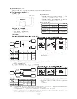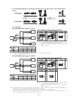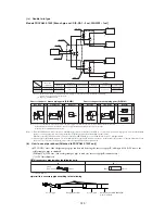
‑
‑
212
(
1
)
<Precautions for wiring>
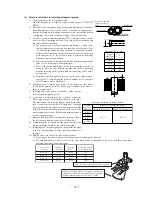
4) Installation procedure
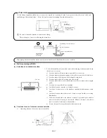
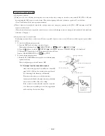
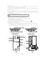
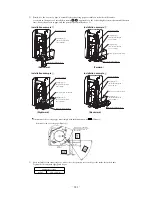
a) Taking out connectors CnF2 and CnF3 from the protection tubes(Fig.A), disconnect the connectors.(Fig.B‑①)
b) Disconnecting wires at the outside of control box from the unit clamps(Fig.B‑②), disassemble the control box from
the unit.(Fig.B‑③)
c) Remove the lid from the control box.(Fig.B‑④)
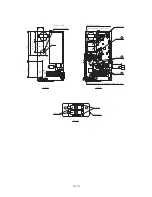
d) Remove the capacitor, fuse and the wires indicated in the figure.(Fig.C)
e) When no hole to mount the capacity is provided on the box, bore a φ3 hole.(Fig.D)
f ) Install the fuse and the label on the bracket.(Fig.F)
g) Install the capacitor, bracket(fuse) and fan controller.(Fig.G)
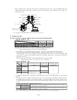
h) Referring to 3) Electric circuit diagram , connect wires as illustrated and fix with bands a .(Fig.G)
i ) Reinstall the removed lid on the control box.
j ) Install the control box in the reverse order of removal and hook the wires at the outside of box on the clamp.
k) Connect the connectors CnF2 and CnF3 and reinstall the protection tubes removed in the step a) above.(Fig.H)
(Install the protection tubes in a manner that they will shield wires completely.)
○ Connect wires correctly as shown by the electric wiring diagram. Be sure to tighten set screws firmly to prevent
them generating heat or causing other troubles after becoming loose.
○ Number of wires connected to the terminal block must be 2 wires or less. Never connect 3 or more wires in any event.
CAUTION
Confirm that electricity has been dischaged before touching
the capacitor terminals. There is risk of electric shocks.
In
d
o
o
r u
n
it
C
o
n
tr
o
l b
o
x
Fig.B
Fig.C
Band b
Fig.H (Same for CnF3)
Protection tube
CnF2
Cut the band off
Fig.A (Same for CnF3)
Move the protection tube to one side
Wire protection tube
CnF2
Wire protection tube
Wire protection tube
Wire protection tube
Cut the band off
(
w
o
o
d
en
b
as
e
sid
e)
Band b
CnF2,3
6
4
2
5
2
F
L
5
1
3
5
2
F
H
7
8
1
3
7
5
4
2
8
6
CnF2,3(6P white)
Separate from
the hook ③
Remove
Disconnect the
connector ①
Separate from
the hook ④
Remove
screws ④
Remove
screws ③
Remove
wires ②
Remove
Remove
Remove
F
1
(
6
.3
A
)
F
2
(
6
.3
A
)
CFI2
CFI1
Summary of Contents for FDCVA1002HESAR
Page 107: ... 106 60 17 150 b Wireless remote controller Unit mm ...
Page 119: ... 118 Model FDCVA1002HESAR Polar white ...
Page 133: ......

